1
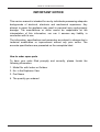
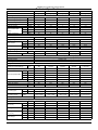
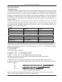
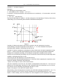
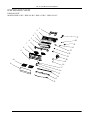
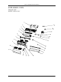
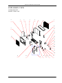
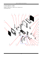
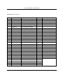
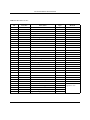
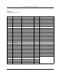
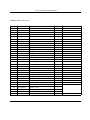
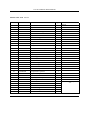
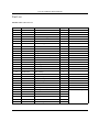
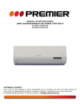
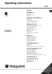
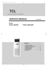
OB207t-1qxp
25/9/97 8:51 PM
Page 1
DEKKER
WALL MOUNTED SPLIT-TYPE AIR CONDITIONERS
SERVICE MANUAL
No.TE100409
Models
DSH 95 R/C
DSH 135 R/C
DSH 265 R/C
DSH 105 R/C
DSH 195 R/C
CONTENTS
1.
2.
3.
4.
5.
6.
IMPORTANT NOTICE
···································2
TECHNICAL SPECIFICATION
·····················3
OPERATION DETAILS·······································4
WIRING DIAGRAM
············· 12
EXPLOSION VIEW
····························15
PARTS LIST
·············20
BERG Air Conditioner Service Manual
IMPORTANT NOTICE
This service manual is intended for use by individuals possessing adequate
backgrounds of electrical, electronic and mechanical experience. Any
attempt to repair the appliance may result in personal injury and property
damage. The manufacturer or seller cannot be responsible for the
interpretation of this information, nor can it assume any liability in
connection with its use.
The information, specifications and parameter are subject to change due to
technical modification or improvement without any prior notice. The
accurate specifications are presented on the nameplate label.
How to order spare parts
To have your order filled promptly and correctly, please furnish the
following information:
1. Model No. with Indoor or Outdoor
2. No. in the Explosion View
3. Part Name
4. The quantity you ordered
2
DEKKER Air Conditioner Service Manual
Technical Specifications
Model No.
DSH 95 R/C
Type
Heating Pump
DSH 105 R/C
Heating Pump
Control type
DSH 135 R/C
DSH 195 R/C
DSH 265 R/C
Heating Pump
Heating Pump
Heating Pump
Remote Controller
Rated cooling capacity
Btu/h;W
7000
9000
12000
18000
24000
Rated heating capacity
Btu/h;W
7200
9500
12800
19000
24500
EER for cooling
Btu/h.w
8.97
8.94
9.01
9.14
9
COP for heating
W/W
2.89
2.63
2.75
2.75
2.7
Moisture removal
Indoor noise level at
cooling
Liters/h
0.5
0.8
1
1.5
2.4
High
Med.
dB(A)
dB(A)
36
33
36
33
37
34
42
39
49
46
Low
dB(A)
29
29
32
36
42
dB(A)
50
50
52
58
58
V
198~264
198~264
198~264
198~264
198~264
Cooling
A
3.6
4.6
6.0
9.0
13.0
Heating
A
3.3
4.8
6.2
9.2
13.8
Cooling
W
780
1010
1330
1970
2600
Heating
W
730
1060
1360
2020
2800
Outdoor noise level
Electrical Data
Power supply
220-240V~/50Hz/1P
Voltage Range
Rated current
Rated input
Refrigerating System
Refrigerant/Charge
Compressor
Gram
Type
R22
R22
R22
R22
R22
Rotary
Rotary
Rotary
Rotary
Rotary
Evaporator
Hydrophilic & Louver Fin; Innergroover tube type (φ7)
Condenser
Louver or Corrugated Fin; Innergroover tube type (φ9.52 or φ7)
Expansion device
Capillary tube
Defrosting system
Microcomputer controlled reverse system
Fan System
Indoor air
circulation(Cooling/Heating)
m3/h
430
Cross flow
Cross flow
Cross flow
Cross flow
Cross flow
Cooling
rpm
1270/1170/1000
1270/1170/1000
1270/1170/1000
1300/1220/1150
1300/1220/1150
Heating
rpm
1250/1150/1000
1250/1150/1000
1250/1150/1000
1300/1220/1150
1300/1220/1150
Dry
rpm
1000
1000
1000
1150
1150
Sleep
rpm
1000
1000
1000
1150/1150
1150
Indoor fan type
Indoor fan speed H/M/L
Indoor fan motor output
W
Outdoor fan type
430/430
530/530
800/850
1100/1100
12
12
12
23
35
Propeller
Propeller
Propeller
Propeller
Propeller
Outdoor fan speed
rpm
895
895
860
850
840
Outdoor fan motor output
W
25
20
31
55
55
Connections
Connecting Pipe
Connecting Wiring
Gas
Inches
Φ9.52(3/8'')
Φ9.52(3/8'')
Φ12.7(1/2'')
Φ12.7(1/2'')
Φ15.88(5/8'')
Liquid
Inches
Φ6.35(1/4'')
Φ6.35(1/4'')
Φ6.35(1/4'')
Φ6.35(1/4'')
Φ9.52(3/8'')
1.0x3; 0.75x2
1.0x3; 0.75x2
1.0x3; 0.75x2
1.5x3; 0.75x2
4×0.75;2×0.75
Size x Core
number
O.D 16mm
Drainage Pipe
Others
m2
6~10
9~16
15~23
20~35
30~50
mm
718x240x180
718x240x180
770x240x180
900x280x202
1033x313x202
Outdoor mm
820x605x300
Suitable area
Net dimensions
(W x H x D)
Net weight
Packing dimensions
(W x H x D)
Gross weight
Indoor
600x500x232
600x500x232
700x552x256
820x605x300
kg
7
7
8
11
14
Outdoor kg
23
24
30
41
52
mm
805×305×265
805x305x265
855x305x265
995x365x298
1103x400x300
Outdoor mm
745x542x353
745x542x353
803x598x380
965x650x438
965x650x438
kg
9
9
10
14
17
Outdoor kg
26
27
34
45
58
Indoor
Indoor
Indoor
3
HPC Air Conditioner Service Manual
Operation Details
1 Remote controller
Remote controller
The remote controller transmits signals to the system.
1 ON/OFF button
Used to start and stop operation
when pressed.
2
SLEEP TIMER ON TMIER OFF
FEEL
COOL
DRY
FAN
HEAT
AUTO
HIGH
MID
LOW
SWING
3
3
5
SLEEP
FAN
7
2
TIMER
SWING
6
ON/OFF
1
8
MODE
TIMER button
Used to select TIMER operation.
UP button (TOO COOL button)
Used to increase the set room temperature
and time.
4
DOWN button (TOO WARM button)
Used to decrease the set room temperature
and time.
5
SLEEP button
Used to set or cancel sleep mode operation.
4
6
VANE control button
Used to adjust airflow direction.
7
FAN SPEED control button
Used to select the indoor fan motor speed:
Auto, High, Mid and Low.
8
MODE button
Used to select the type of operation mode: Feel,
Cooling, Dry, Fan and Heating(Only for Heat Pump).
Note: Each mode and relevant function will be further specified in following pages.
Remote Control
The remote controller is not presetted as Cooling Only Air Conditioner or Heat Pump by manufacturer.
Each time after the remote controller replace batteries or is energized, the arrowhead will flashes on the front of
Heat or Cool on LCD of the remote controller.
User can preset the remote controller type depending on the air conditioner type you have purchased as
follows:
Press any button when the arrowhead flashes on the front of Cool , Cooling Only is set.
Press any button when the arrowhead flashes on the front of
Heat , Heat Pump is set.
If you don t press any button within 10 seconds, the remote controller is preset as Heat Pump automatically.
Note :
If the air conditioner you purchased is a Cooling Only one, but you preset the remote controller as Heat Pump, it
doesn t bring any matter. But if the air conditioner you purchased is a Heat Pump one, and you preset the
remote controller as Cooling Only, then you CAN NOT preset the Heating operation with the remote controller.
4
HPC Air Conditioner Service Manual
Electronic controller:
1.Automatic mode
1) Initial RT determines the working mode and ST,the mode is determined effective only once unless
A/C shut-down then re-started. If from other modes switches to autoamatic mode (including mode
conversion after shutdown), it should be that the compress stop more than 3 min then temperature
judgement and automatic mode are conducted (it can conduct immediately from fan mode switched
to automatic, the indoor fan stops, three minutes later the response is made and start up). Within 3
min, the output as: Showing the room temperature, indoor fans starts (or anti-cold airflow), the
outdoor fan stops;
2) With memory controller, once being turned off or in case of an accidently power cut, the A/C is able
to retain and restore the original mode when being turned on or the power supply is resumed, if the
auto restart function activated. power-down after power-on; while if the auto restart fundction isn’t
activated, the A/C enters standby state.
Heat pump
Mode
Initial RT
Initial ST
RT≥26℃
23℃
Cooling
26℃>RT≥20℃
18℃
Dehumifying
RT<20℃
23℃
Heating
Cooling-only
Mode
Initial RT
Initial ST
RT≥26℃
23℃
Cooling
26℃>RT≥20℃
18℃
Dehumifying
RT<20℃
-
Ventilating
Under automatic mode (including from automatic converted into dehumidifying Dry mode), when the
temperature up and down signals from the remote controller is received, the setting temperature ST
adjusts correspondingly to the current room temperature plus or minus 1℃, the automatic regulating
temperature range is ± 2℃.
2.Cooling mode
1) The control of the compressor
a. When RT-ST≥1℃,the compressor is running.
b. When RT-ST<-1℃,the compressor is off.
c. When -1℃≤RT-ST<1℃, the compressor keeps its original state.
2) Outdoor fan motor and the compressor run simultaneously (except for defrosting).
3) The control of indoor fan motor:
a. Indoor fan motor can operate by automatic, low, middle, and high airflow speed circularly.
b. Indoor fan motor’s the automatic airflow speed control Indoor fan motor can operate by automatic,
as shown in Figure 1:
Hi
Mid
Lo
RT-ST
1℃
2℃
4℃
Figure 1 Cooling automatic airflow
When the temperature changes lead to changes in airflow speed, the switch can only be made
orderly, and every grade of air flow speed runs 1 minute at least.
5
HPC
Air Conditioner Service Manual
3, Dry mode
running into this mode, the Air cond. firstly operates for 3 minutes according to cooling mode (set
temperature is 7℃) , and then takes the detected backflow air temperature minus 2℃ as a new set
temperature (the minimum value of 5℃) and runs according to cooling mode, indoor fan operates at
low-speed, at this moment the setting operation of Fan speed is invalid but Swing is adjustable.
4. Heating mode
On the Heating mode, the room temperature is repaired. After repaired, the room temperature
display on the LED CRT=RT-3℃.
1) The control of the compressor
a. When ST-CRT≥1℃,the compressor is running.
b. When ST-CRT<-1℃,the compressor is off.
c. When -1℃≤ST-CRT<1℃, the compressor keeps its original state
2) Outdoor fan motor and the compressor run simultaneously (except for defrosting)
3) The control of indoor fan motor:
a. Indoor fan motor can operate by automatic, low, middle, and high airflow speed circularly.
b. indoor fan motor’s the automatic airflow speed control Indoor fan motor can operate by automatic,
as shown in Figure 2:
Hi
Mid
Lo
ST-CRT
1℃
2℃
4℃
Figure 2 Heating automatic airflow
When the temperature changes lead to changes in airflow speed, the switch can only be made
orderly, and every grade of air flow speed runs 1 minute at least.
4) Vane motor control: run as set state.
5) 4-way valve control:
a. Under heating mode, the four-way valve maintains well-connected status (including the
compressor stops on set condition, but except for the defrosting process)
b. When the mode switches into the heating mode or start-up, four-way valves will open 5 Seconds
before the compressor starts; while the mode exits from the heating mode or turn off, the four-way
valve will close 2min after after the shut-down the compressor.
6) Defrosting function:
During defrosting, once mode switch, temperature setting signals received, and the buzzer and
display make response immediately, but the other operations won’t implemented until defrosting
finished;
During defrosting, the signals of on-off, timing, sleep, airflow speed ans swing will be responded, but
the airflow speed and swing should be in accordance with anti-cold air rules.
Except the above signal processing during defrosting, no other signals will be dealt with, but only a
loud buzz.
During defrosting, electrical heating stops compulsively.
Defrosting enter and exit pragram:
Option 1:with jumper JC
The condition of enter defrosting: run into defrosting once any of condition 1, 2, and 3 met.
6
HPC
Air Conditioner Service Manual
Condition 1:As shown in figure 3
Defination:
The followings are all required to meet:
a. IPT1 settles for IPT1=IPTmax-△IPT(8℃)
b. t5≥50min(running time t5≥50min(the compressor runs cumulatively),t5 is removable,and could
be less than t1)
c. IPT<40℃,and lasts 2min。
Running into defrosting on condition 1, the first running time of set defrosting is F (8min); after running
a defrosting cycle, the defrosting time should be determined and adjusted.
Figure 3
Condition 2: When running time is more than or equal to 120 min (compressor is running
accumulatively), the indoor temperature is less than 35 ° C for 2 min sustained. Running into
defrosting under condition 2, defrosting time set is 8 min.
Condition 3: after the compressor is operating for 20min continuously, the indoor temperature is less
than 23 ° C which is anti-cold wind temperature when the fan stops running(including temperature
droping when compressor operating, not including the compressor’s starting course), and the
machine runs into defrosting according to any one condiciton as below) Running into defrosting under
condition 3, defrosting time set is 10 min.
a) Running into the first defrosting in 20 min after start-up.
b) The interval from last defrosting equivalent to or more than 50 min (stopping the compressor or the
machine in standby is allowed in the meantime).
Option 2: No Jumper JC, and no OPT outdoor sensor
when the compressor runs for 45 min, if the indoor coil temperature is less than 40 ° C for 2 min, the
machine runs into defrosting, and lasts for 3min, otherwise when the compressor runs for 120 min,
the machine runs into defrosting automatically and last for 10 min.
Option 3: No jumper JC, but with OPT outdoor sensor
When heating, when the temperature of outdoor unit under heat-exchange is lower than E ° C (-4 ° C),
and the compressor runs for 45 min, then the machine runs into defrosting and last for 10 min.
Option 4. When heating, when the outdoor fan motor stopped but the compressor not stopped
7
HPC
Air Conditioner Service Manual
accumulative total 30min, then the machine runs into defrosting and last for 8 min. if the accumulative
total less than 30min, but accord with one of the condition option 1-3 them the machine runs into
defrosting at the option 1-3 and the accumulative tota time restarts from 0.
Conditions for quitting defrostng
(1) The quitting conditions for option 1 and option 2, the machine quits from defrosting if any one
below condition met.
a. Defrosring time is over.
b.When it runs in defrosting for three minutes, the IPT indoor coil temperature rises 15 ° C or above
from the bottom point.
(2) The quitting conditions for option 3.
When OPT ≥ 20 ° C or defrosting for more than 10 min, then quit from defrosting.
(3) Defrosting process shown in Figure 4
Figure 4 Defrosting process
7) Auxiliary Electric heating function
(1)The default condition is automatic on/off the electric heating function.
(2) The conditions of auxiliary electric heating(all the following conditions must be met)
a. the compressor runs for more than 3min;
b. indoor fan runs normally;
c. not in defrosting state;
d. auxiliary electric heating is turned off for more than 30s。
e. ST-RT≥3°C;
f. RT﹤22°C;
g. IPT≤43°C;
(3) The conditions of stopping auxiliary electric heating(any one of the following conditions met, the
state stops)
a. the compressor stops
b. RT≥24°C;
c. IPT≥48°C
d. indoor fan stops。
e. running into sleeping function
5. Fan mode
1) Indoor fan motor control:
8
HPC Air Conditioner Service Manual
indoor fan motor is running at setting speed (the speed is same as that of heating).
2) Vane motor control: running according to the setting.
3) The outdoor unit is not working under fan mode.
6. Sleeping mode
1) Under sleep mode, the indoor fan motor is running at a low-airflow speed,except that the power
light and sleep light are on, timer light is on/off according to the setting state, running light is off. LED
is off after displaying 5min.
2) Temperature control:
(1) From cool mode to sleep mode, one hour later, the operates Temp.=ST+1,another one hour
later, the operates Temp.=ST+2,after then unchanged.
(2) From heating mode to sleep mode, one hour later, the operates Temp.= ST-1,another one hour
later, the operates Temp.=ST-2,after then unchanged.
3) the machine will automatically shut up after running 8 hours under sleep mode.
Timer on start-up and sleep mode are implemented at the same time, and the sleep mode can not be
functioned.
7. Timing fuction
The timing scale is between 10min to 24h, when the time fixed is less than “10” hours, the displayed
time is shown by 0.5 hour as the unit, when the time fixed is more than or equal to “10” hours, the
displayed time is shown by 1 hour as the unit.
8. Emergency switch(ON/OFF)
1) When stand-by, to operate by pressing the emergency switch as follows:
To Press the emergency switch in three seconds, the buzzer rings once, and to release, the machine
runs into cooling mode; if to holding on, the buzzer rings twince, then the machine runs into heating
mode, while when the machine is on, to press the emergency Switch, the buzzer rings once and then
the machine shut down.
2) The machine is running mandatorily as the selected mode within 30min after emergency operation,
indoor fan motor is running in high-speed, and vane board is swinging. The machine runs into
automatic mode 30min later, the selected mode unchanged, the set temperature is 23° C ,the rotate
speed of indoor fan motor is automatic, and vane board is swinging too.
3) To press the emergency button when the machine operating, then the machine runs into stand-by
state.
4) Under emergency operation,the Compressor’s time-lapse protection, anti-frosting protection in
cooling, Overheating protection in heating and sensor fault protection and defrost operate are
effective.
5) Under emergency operation, once effective signal from remote controller is received, then the
machine exits form the emergency mode, and operate according to the setting from remote controller.
9. Auto-restart function
1) The PCB retains the setting parameters in case of power off. When the power supply is resumed,
the machine, which has been started up the power-off memory function, is able to restore into the
original running state automatically.
2) To press the emergency button and power on, and hold on 10 seconds, exit from the power-off
memory function, buzzer rings four tomes.(default: no this function)
10. Protection/ Troubleshooting functions
9
HPC
Air Conditioner Service Manual
1) Compressor’s protection function:
a.The PCB which has Power-off memory function, once this function is started up,the compressor
goes along 3min delay protection when power on. If the PCB hasn’t been started up this function,
even when the PCB is power-on, the compressor doesn’t process 3 min delay function.
b.Compressor’s 3 min interval protection: the compressor can’t start-up until 3 min later(except for
defrosting process).
c.After the compressor started, the compressor’s state isn’t subject to the changes on ST,RT in 3min.
2) Anti-frosting protection of indoor evaporator:
If IPT ≤ 0 ℃ detected in consecutive 5 min, compressor and outdoor motor stoped, indoor fan motor
runs at high-speed forcibly; IPT ≥ 5 ℃ detected 3min later, then outdoor fan is activated. And the
compressor, indoor fan motor restores the original state.
3) Overheating protection:
IPT ≥ 55℃, the outdoor fan stops, IPT ≥ 65℃, the compressor stops, indoor fan motor runs at
high-speed forcibly. When IPT ≤ 48℃, outdoor fan motor and the compressor open, indoor fan motor
restores the original state.
4) Anti-cold wind control in heating:
a. When runing into the heating mode, once the compressor fails to comply with the start-up
conditions, the wind speed is regulated according to the coil temperature in 2 min(including stopping
the indoor fan motor), 2 min later the indoor fan motor stops.If the compressor starts up within 2 min,
then operating by Figure 5.
Under heating process, to close the compressor (including the downtime protection ), the wind speed
is regulated according to the coil temperature in 1min(including stopping the indoor fan), 1min later
the fan is stoped forcibly.
b. When the indoor fan motor running at a low-speed wind and in anti-cold wind operation, once
electric heating opens,the vane immediately withdraws from the anti-cold windy location and turn
back to normal vane angle. When electric heating closes, indoor fan motor go on to run at low-speed
wind, accordingly, the vane turns to anti-cold windy location.
Figure 5 Anti-cold Wind
2) The following table shows the fault protections. When failures happens, the PCB alarms and
buzzer rings three times. Failure code appears, and the PCB operates protection procedures.
10
HPC Air Conditioner Service Manual
Failure code: For the machine has LED, the code displays on LED, for no LED machine, the code
reflects by the running light.
Failure
Running Light Flash
LED Display
RT Sensor Failure
Once / Period
E1
IPT Sensor Failure
Twice / Period
E2
Indoor Fan Motor Failure
6 times / Period
E6
When there is LED displaying failure code, the code is displayed statically, if there are several failure
codes should be reported at the same time, then failure codes appears one by one every eight
seconds correspondingly.
a. Sensor’s failure protection: when the sensor’s temperature is out of the range -50 ≤ T ≤ 110 ℃,
then sensor failue is determined. Once RT, IPT sensor failures appear, the compressor stops and
indoor and outdoor fan motors shut off. Remote controller deesn’t response to any signal except for
shutdown. During failure the machine can run in fan mode. After the failure is settled, the PCB
restores to standby status.
b. Failure protection of Indoor PG fan motor:If there is no feedback signal of rotate speed within 5, the
indoor fan motor stops,at the same time, the compressor, outdoor fan moto, four-way valve and
auxiliary electric heater etc cut downn. 10 seconds later, the indoor fan motor restarts, once there is
no feedback signal of rotate speed within 5 seconds either, then the machine stops and goes into
indoor fan motor failure protection, buzzer rings three times, and running light flashes at 6 times per 8
seceonds. When the failure is confirmed, once there is feedback signal,the failue is relieved
automatic.
11
HPC Air Conditioner Service Manual
WIRING DIAGRAM
MODEL:DSH 95 R/C, DSH 105 R/C, DSH 135 R/C
INDOOR UNIT:
OUTDOOR UNIT
12
HPC Air Conditioner Service Manual
WIRING DIAGRAM
MODEL:DSH 195 R/C
INDOOR UNIT:
OUTDOOR UNIT
13
HPC Air Conditioner Service Manual
WIRING DIAGRAM
MODEL:DSH 265 R/C
INDOOR UNIT:
OUTDOOR UNIT
14
TCL Air Conditioner Service Manual
EXPLOSION VIEW
INDOOR UNIT:
MODEL:DSH 95 R/C, DSH 105 R/C, DSH 135 R/C, DSH 195 R/C
1
2
3
4
27
5
26
6
7
25
24
8
9
23
22
21
20
19
10
11
18
17
16
15
14
13
12
15
TCL Air Conditioner Service Manual
EXPLOSION VIEW
INDOOR UNIT:
MODEL: DSH 265 R/C
1
2
2
3
2
4
5
25
6
24
23
7
22
8
21
9
10
20
1
11
18
17
16
12
13
14
15
16
HPC Air Conditioner Service Manual
EXPLOSION VIEW
OUTDOOR UNIT:
MODEL: DSH 95 R/C
7
8
6
4
5
3
1
2
27
9
26
25
10
24
23
22
21
20
19
18
11
12
13
17
14
15
16
17
HPC Air Conditioner Service Manual
EXPLOSION VIEW
MODEL: DSH 105 R/C, DSH 135 R/C, DSH 195 R/C
OUTDOOR UNIT:
7
6
4
5
3
1
2
26
8
25
24
9
23
22
21
20
19
18
17
10
11
12
18
13
14
15
16
HPC Air Conditioner Service Manual
EXPLOSION VIEW
MODEL: DSH 265 R/C
OUTDOOR UNIT:
7
6
4
5
3
1
2
27
26
8
25
24
23
9
22
21
20
19
18
17
10
11
12
19
13
14
15
16
TCL Air Conditioner Service Manual
Indoor Unit- DSH 95 R/C
No.
1
2
3
4
5
6
7
8
9
10
11
12
13
14
15
16
17
18
19
20
21
22
23
24
25
26
27
29
29
30
31
32
Part No.
1080030003
1210250103
1070020017
1070100010
1210231201
1070251833
1070321035
1070251841
1070320112
1070250106
1070251941
1170120042
1070251837
1070110011
1070321024
1090320291
1070321181
1070040004
1170020011
1090250016
1073030201
1070320113
1070320111
1170030047
1170240001
1170230001
1070320101
1090050649
1070060003
1190250885
1191990102
1191990103
Part Name
Installation Plate
Base
Cross Fan
Bearing Mount
Evaporator
Water Drainage Assembly
Vertical Vane Assembly
Face Frame
Screw Cover
Air Filter
Front Panel
Power Supply Cord
Vane
Drainage Hose
Display PCB Cover
Display PCB(Digital)
Display PCB Box
Cable Clamp
Vane Motor
Main PCB(Digital)
Sensor Holder
Electrical Box
Indoor Motor Cover
Indoor Motor
Transformer
Indoor Sensor Assembly
In And Out Pipe Fixer
Remote Controller
Remote Controller Supporter
Indoor Carton
Left Foaming
Right Foaming
20
Q’ty
1
1
1
1
1
1
2
1
2
2
1
1
1
1
1
1
1
1
1
1
1
1
1
1
1
1
1
1
1
1
1
1
Remark
Not shown in Explosion view
TCL Air Conditioner Service Manual
Indoor Unit- DSH 105 R/C
No.
1
2
3
4
5
6
7
8
9
10
11
12
13
14
15
16
17
18
19
20
21
22
23
24
25
26
27
29
29
30
31
32
Part No.
1080030003
1210250103
1070020017
1070100010
1210231201
1070251833
1070321035
1070251841
1070320112
1070250106
1070251941
1170120042
1070251837
1070110011
1070321024
1090320291
1070321181
1070040004
1170020011
1090250016
1073030201
1070320113
1070320111
1170030047
1170240001
1170230001
1070320101
1090050649
1070060003
1190250885
1191990102
1191990103
Part Name
Installation Plate
Base
Cross Fan
Bearing Mount
Evaporator
Water Drainage Assembly
Vertical Vane Assembly
Face Frame
Screw Cover
Air Filter
Front Panel
Power Supply Cord
Vane
Drainage Hose
Display PCB Cover
Display PCB(Digital)
Display PCB Box
Cable Clamp
Vane Motor
Main PCB(Digital)
Sensor Holder
Electrical Box
Indoor Motor Cover
Indoor Motor
Transformer
Indoor Sensor Assembly
In And Out Pipe Fixer
Remote Controller
Remote Controller Supporter
Indoor Carton
Left Foaming
Right Foaming
21
Q’ty
1
1
1
1
1
1
2
1
2
2
1
1
1
1
1
1
1
1
1
1
1
1
1
1
1
1
1
1
1
1
1
1
Remark
Not shown in Explosion view
TCL Air Conditioner Service Manual
Indoor Unit- DSH 135 R/C
No.
1
2
3
4
5
6
7
8
9
10
11
12
13
14
15
16
17
18
19
20
21
22
23
24
25
26
27
28
29
30
31
32
Part No.
1080030008
1210320107
1070020026
1070100010
1210320601
1070321032
1070321035
1070321030
1070320112
1070250106
1070322132
1170120045
1070321034
1070110011
1070321024
1090320291
1070321181
1070320114
1300321241
1070320113
1170020011
1073030201
1170030047
1070320111
1170240001
1170230001
1070320101
1090050649
1070060003
1190320879
1191990102
1191990103
Part Name
Installation Plate
Base
Cross Fan
Bearing Mount
Evaporator
Water Drainage Assembly
Vertical Vane Assembly
Face Frame
Screw Cover
Air Filter
Front Panel
Power Supply Cord
Vane
Drainage Hose
Display PCB Cover
Display PCB(Digital)
Display PCB Box
Cable Clamp
Main PCB(Digital)
Electrical Box
Vane Motor
Sensor Holder
Indoor Motor
Indoor Motor Cover
Transformer
Indoor Sensor Assembly
In And Out Pipe Fixer
Remote Controller
Remote Controller Supporter
Indoor Carton
Left Foaming
Right Foaming
22
Q’ty
1
1
1
1
1
1
2
1
2
2
1
1
1
1
1
1
1
1
1
1
1
1
1
1
1
1
1
1
1
1
1
1
Remark
Not
shown
Explosion view
in
TCL Air Conditioner Service Manual
Indoor Unit- DSH 105 R/C
No.
1
2
3
4
5
6
7
8
9
10
11
12
13
14
15
16
17
18
19
20
21
22
23
24
25
26
27
29
29
30
31
32
Part No.
1080030003
1210250103
1070020017
1070100010
1210231201
1070251833
1070321035
1070251841
1070320112
1070250106
1070251941
1170120042
1070251837
1070110011
1070321024
1090320291
1070321181
1070040004
1170020011
1090250016
1073030201
1070320113
1070320111
1170030047
1170240001
1170230001
1070320101
1090050649
1070060003
1190250885
1191990102
1191990103
Part Name
Installation Plate
Base
Cross Fan
Bearing Mount
Evaporator
Water Drainage Assembly
Vertical Vane Assembly
Face Frame
Screw Cover
Air Filter
Front Panel
Power Supply Cord
Vane
Drainage Hose
Display PCB Cover
Display PCB(Digital)
Display PCB Box
Cable Clamp
Vane Motor
Main PCB(Digital)
Sensor Holder
Electrical Box
Indoor Motor Cover
Indoor Motor
Transformer
Indoor Sensor Assembly
In And Out Pipe Fixer
Remote Controller
Remote Controller Supporter
Indoor Carton
Left Foaming
Right Foaming
23
Q’ty
1
1
1
1
1
1
2
1
2
2
1
1
1
1
1
1
1
1
1
1
1
1
1
1
1
1
1
1
1
1
1
1
Remark
Not shown in Explosion view
TCL Air Conditioner Service Manual
Part List
Indoor Unit- DSH 265 R/C
No.
1
2
3
4
5
6
7
8
9
10
11
12
13
14
15
16
17
18
19
20
21
22
23
24
25
26
27
28
29
30
31
32
33
Part No.
1080030001
1070701047
1070020014
1070100010
1110050321
1070701048
1070701050
1070701051
1070701060
1073090111
1073090112
1073090113
1070701284
1070700511
1300700890
1073090114
1070701052
1070701053
1070110011
1074060118
1170020041
1090700403
1073030201
1073090121
1073090120
1170030048
1173090107
1170230001
1090050649
1070060003
1190500155
1150700001
1150700002
1190060021
1190060021
Part Name
Installation Plate
Base
Cross Fan
Bearing Mount
Evaporator
Water Drainage Assembly
Vertical Vane Assembly A
Vertical Vane Assembly B
Face Frame
Screw Cover
Left Air Filter
Right Air Filter
Front Panel
Display PCB Cover
Display PCB(Digital)
Electrical Box Cover
Vane A
Vane B
Drainage Hose
Cable Clamp
Vane Motor
Main PCB(Digital)
Sensor Holder
Electrical Box
Indoor Motor Cover
Indoor Motor
Transformer
Indoor Sensor Assembly
Remote Controller
Remote Controller Supporter
Indoor Carton
Left Foaming
Right Foaming
Middle Pasteboard Supporter
Middle Foaming Supporter
24
Q’ty
1
1
1
1
1
1
1
1
1
3
1
1
1
1
1
1
1
1
1
1
2
1
1
1
1
1
1
1
1
1
1
1
1
1
1
Remark
Not shown in Explosion view
HPC Air Conditioner Service Manual
Part List
Outdoor Unit- DSH 95 R/C
No.
1
2
3
4
5
6
7
8
9
10
11
12
13
14
15
16
17
18
19
20
21
22
23
24
25
26
27
28
29
30
31
Part No.
1083510901
1081990014
1110061174
1081990018
1170040062
1070030006
1081990011
1080320147
1081990016
1071990044
1100060199
1120110002
1120200477
1091990046
1081990012
1120120008
1081990013
1120130011
1073521301
1070040001
1070040002
1170500131
1170100031
1170100014
1080010006
1080020001
1120200476
1190070014
1190200313
1190070016
1190070015
Part Name
Grille
Top Cover
Condenser
Outdoor Motor Supporter
Outdoor Motor
Propeller Fan
Left Grille Supporter
Left airproof plate
Front Plate
Fan Guard
Compressor And It Accessories
4-way Valve
4-way Valve Assembly
Base
Right Plate
Two-way Valve
Valve Supporter
Three-way Valve
Electrical Box Cover
Cable Clamp(φ6)
Cable Clamp(φ7)
Terminal
Fan Motor Capacitor
Compressor Capacitor
Capacitor Strip
Electrical Parts Box
Capillary Assembly
Base Carton
Cabinet Carton
Base Foaming
Cover Forming
25
Q’ty
1
1
1
1
1
1
1
1
1
1
1
1
1
1
1
1
1
1
1
1
1
1
1
1
1
1
1
1
1
1
1
Remark
Optional
Not shown in the Explosion view.
TCL Air Conditioner Service Manual
Part List
Outdoor Unit- DSH 105 R/C
No.
1
2
3
4
5
6
7
8
9
10
11
12
13
14
15
16
17
18
19
20
21
22
23
24
25
26
27
28
29
30
31
Part No.
1071990038
1081990014
1300230293
1081990018
1170040071
1070030006
1081990011
1081990016
1071990044
1100170010
1120110002
1120250991
1091990046
1081990012
1120120008
1081990013
1120130011
1073521301
1070040001
1070040003
1170500131
1170100031
1170100014
1080010006
1081990010
1120250988
1081990019
1190070014
1190070008
1190070016
1190070015
Part Name
Grille
Top Cover
Condenser
Outdoor Motor Supporter
Outdoor Motor
Propeller Fan
Left Grille Supporter
Front Plate
Fan Guard
Compressor
And
It
4-way Valve
4-way Valve Assembly
Base
Right Plate
Two-way Valve
Valve Supporter
Three-way Valve
Electrical Box Cover
Cable Clamp(φ6)
Cable Clamp(φ8)
Terminal
Fan Motor Capacitor
Compressor Capacitor
Capacitor Strip
Electrical Parts Box
Capillary Assembly
Partition plate
Base Carton
Cabinet Carton
Base Foaming
Cover Forming
26
Q’ty
1
1
1
1
1
1
1
1
1
1
1
1
1
1
1
1
1
1
1
1
1
1
1
1
1
1
1
1
1
1
1
Remark
Optional
Not shown in the Explosion view.
TCL Air Conditioner Service Manual
Outdoor Unit- DSH 135 R/C
No.
1
2
3
4
5
6
7
8
9
10
11
12
13
14
15
16
17
18
19
20
21
22
23
24
25
26
27
29
30
31
32
Part No.
1071990039
1080320105
1110060973
1080050004
1170040058
1070030033
1080050001
1080320113
1080320112
1100170028
1120110002
1120320915
1081990209
1080050002
1120120016
1080050003
1120130021
1073551103
1070040002
1070040003
1170500131
1170100010
1170100003
1080010006
1081990010
1120320914
1081990019
1190070017
1190320718
1190070019
1190070018
Part Name
Q’ty
Grille
Top Cover
Condenser
Outdoor Motor Supporter
Outdoor Motor
Propeller Fan
Left Grille Suppoeter
Front Plate
Fan Guard
Compressor And It Accessories
4-way Valve
4-way Valve Assembly
Base
Right Plate
Two-way Valve
Valve Supporter
Three-way Valve
Electrical Box Cover
Cable Clamp(φ7)
Cable Clamp(φ8)
Terminal
Fan Motor Capacitor
Compressor Capacitor
Capacitor Strip
Electrical Parts Box
Capillary Assembly
Partition plate
Base Carton
Cabinet Carton
Base Foaming
Cover Forming
27
1
1
1
1
1
1
1
1
1
1
1
1
1
1
1
1
1
1
1
1
1
1
1
1
1
1
1
1
1
1
1
Remark
Optional
Not shown in the Explosion view.
TCL Air Conditioner Service Manual
Outdoor Unit- DSH 195 R/C
No.
1
2
3
4
5
6
7
8
9
10
11
12
13
14
15
16
17
18
19
20
21
22
23
24
25
26
27
28
29
30
31
32
Part No.
1083520101
1081990056
1110060506
1081990060
1170040100
1070030040
1081990053
1081990058
1081990059
1100110020
1120110003
1120520760
1081990249
1081990054
1120120016
1081990055
1120130024
1073551103
1070040001
1070040003
1170500131
1170100030
1170100004
1080010006
1081990010
1120501129
1081990071
1174561802
1190070064
1190500898
1190070066
1190070124
Part Name
Grille
Top Cover
Condenser
Outdoor Motor Supporter
Outdoor Motor
Propeller Fan
Left Grille Supporter
Front Plate
Fan Guard
Compressor And It Accessories
4-way Valve
4-way Valve Assembly
Base
Right Plate
Two-way Valve
Valve Supporter
Three-way Valve
Electrical Box Cover
Cable Clampφ6
Cable Clampφ8
Terminal
Fan Motor Capacitor
Compressor Capacitor
Capacitor Strip
Electrical Parts Box
Capillary Assembly
Partition plate
Outdoor sensor
Base Carton
Cabinet Carton
Base Foaming
Cover Forming
28
Q’ty
1
1
1
1
1
1
1
1
1
1
1
1
1
1
1
1
1
1
1
1
1
1
1
1
1
1
1
1
1
1
1
1
Remark
Optional
Not shown in the Explosion
view.
TCL Air Conditioner Service Manual
Part List
Outdoor Unit- DSH 265 R/C
No.
1
2
3
4
5
6
7
8
9
10
11
12
13
14
15
16
17
18
19
20
21
22
23
24
25
26
27
28
29
30
31
32
Part No.
1083520101
1081990056
1110060885
1081990060
1170040100
1070030040
1081990053
1081990258
1071990096
1100040068
1120110001
1120701279
1080500328
1081990054
1120120011
1081990055
1120130013
1073551103
1074060118
1170200054
1170100030
1170100007
1080010006
1081990072
1174561801
1120701269
1081990071
1174561802
1190500898
1190070124
1190070064
1190070066
Part Name
Grille
Top Cover
Condenser
Outdoor Motor Supporter
Outdoor Motor
Propeller Fan
Left Grille Supporter
Front Plate
Fan Guad
Compressor And It Accessories
4-way Valve
4-way Valve Assembly
Base
Right Plate
Two-way Valve
Valve Supporter
Three-way Valve
Electrical Box Cover
Cable Clamp
Terminal
Fan Motor Capacitor
Compressor Capacitor
Capacitor Strip
Electrical Parts Box
AC Contactor
Capillary Assembly
Partition plate
Outdoor Defrost Sensor
Cabinet Carton
Cover Forming
Base Carton
Base Foaming
29
Q’ty
1
1
1
1
1
1
1
1
1
1
1
1
1
1
1
1
1
1
1
1
1
1
1
1
1
1
1
1
1
1
Remark
Optional
Not show in the explosion