1
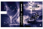
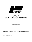
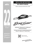
INSTALLATION & MAINTENANCE MANUAL for 305HT This document is the property of Ultra Dynamics Limited and the information contained herein is confidential. Its contents may not be disclosed, copied or used for any purpose other than that for which it is supplied, without the written authority of Ultra Dynamics Limited. Ultra Dynamics Limited Head Office: Upperfield Road, Kingsditch Trading Estate, Cheltenham, Glos GL51 9NY, England. Tel: +44 1242 707900 Fax: +44 1242 707901 Email: [email protected] USA Sales & Service: 1110A Claycraft Road, Columbus, Ohio 43230, USA. Tel: (614) 759 9000 Fax: (614) 759 9046 Email: [email protected] www.ultradynamics.com © Ultra Dynamics Limited 2005 Use or disclosure of data contained herein is subject to the restriction on the title page of this document UD248/19/DTP/3/12 305HT INSTALLATION & MAINTENANCE MANUAL CONTENTS: WARRANTY FORM SECTION 1 GENERAL DESCRIPTION SECTION 2 SPECIFICATION SECTION 3 SCOPE OF APPLICATION SECTION 4 PERFORMANCE SECTION 5 INSTALLATION DETAILS SECTION 6 CONTROL SYSTEM SECTION 7 CORROSION PROTECTION SECTION 8 OPERATION SECTION 9 FAULT FINDING CHART SECTION 10 SERVICING SECTION 11 OVERHAUL SECTION 12 SCHEDULE OF PARTS Use or disclosure of data contained herein is subject to the restriction on the title page of this document UD248/19/DTP/3/12 305HT WARRANTY AND LIABILITY 1. Ultra Dynamics Limited (hereinafter referred to as UDL) warrants that, subject to all terms of this warranty, UltraJet goods will be free from defects due to faulty material or faulty workmanship. UDL’s obligations under this Warranty being limited to make good at its factory or at the factory of any subsidiary or branch of UDL the product, or any part or parts thereof which shall be returned to it. 2. This warranty shall remain in force for 15 calendar months from date of despatch from UDL and relates to all such defects discovered within such period and notified in writing to UDL within forty-five days of discovery, subject to the provisions herein. 3. Any goods alleged to be defective and under warranty should initially be reported to UDL in writing with adequate details of the failure, periods of service and full identification to UDL. Under no circumstances should units be returned without first gaining prior consent from UDL in writing. 4. When UDL consent in writing, the Buyer must return the alleged defective unit to UDL as “failed”, identified, properly packed and full carriage paid. UDL will not accept any units where the full carriage has not been paid. UDL will not accept any charges associated with removal of goods from an installation nor the refitment of goods into the installation. In matters of warranty, UDL shall decide if goods are defective and under warranty and whether to replace or give credit for goods and credit for reasonable carriage costs on accepted claims. 5. Goods replaced under this warranty shall be deemed to be rewarranted in the terms of this warranty for the unexpired period of the warranty under paragraph 2. above. 6. This warranty excludes normal wear and tear, goods which have been subject to any alteration not authorised by UDL, goods which have not been serviced or maintained strictly in accordance with UDL instructions, and goods on or from which the trademark or serial number has been altered, removed or obliterated. 7. All goods supplied are supplied only upon the terms that, save as provided above, all conditions and warranties in respect thereof (whether express or implied and whether statutory or otherwise) are hereby excluded and extinguished, and neither UDL nor its servants or agents shall be under any liability whatever for any personal injury or for any loss or damage of whatever kind (howsoever such personal injury loss or damage be caused) arising directly or indirectly out of or in connection with the design, manufacture, supply installation of such goods or the unsuitability or defectiveness thereof or any advice or services rendered in connection therewith, the intent of this Clause being to exclude save as provided otherwise in this Clause any liability for acts, omissions or matters which are or but for this Clause would be breaches of contract whether of a fundamental term or nature or not, or torts. The Buyer shall on demand indemnify UDL and its servants and agents against any claims in respect of any such personal injury, loss or damage. For the purpose of this Clause UDL contracts on its own behalf and as agents and trustees for its employees, servants and agents. 8. In no circumstances shall UDL incur any higher liability to the Buyer hereunder than the total of the sums paid by the Buyers to UDL for the contract goods in respect of which the liability arises. 9. Any obligation on the part of UDL under this Warranty does not apply to any UDL product which may have been repaired or altered in any way other than by UDL or to damages caused in the opinion of UDL by overloading, misuse, mis-application, improper storage, abnormal wear and tear due to exposure to the elements, negligence, accident, or whilst being operated in any other way other than in accordance with the operating and maintenance instructions of the company nor does it apply to repairs made necessary by the use of parts or accessories not recommended by UDL. Use or disclosure of data contained herein is subject to the restriction on the title page of this document UD248/19/DTP/3/12 305HT 10. There is no liability on the part of UDL with respect to any items incorporated in any UDL product when such items have been manufactured by others and are warranted by their respective manufacturers in favour of the purchaser or when they are supplied by UDL on special order. UDL shall not be liable for any consequential loss or damage resulting directly or indirectly from any defect in the product the subject of this agreement. 11. No liability on the part of UDL with respect to this Warranty shall extend to second-hand and reconditioned goods and the Warranty does not cover the cost of labour involved in the replacement of defective parts. 12. No liability on the part of UDL with respect to this Warranty shall exist if the UDL product is not, in the opinion of UDL, installed as per the Installation and Maintenance Manual or Designer’s Manual. 13. Warranty will not apply unless a negative earth bonding system has been installed in the vessel. ULTRA DYNAMICS LIMITED NOTE: This Section must be completed fully and sent by return to: Ultra Dynamics Limited, Upperfield Road, Kingsditch Trading Estate, Cheltenham, Glos. GL51 9NY, United Kingdom. —————————————————————————————————————————————————— Purchaser …………………………………………………………. Address …………………………………………………………………………………………………………… …………………………………………………………………………………………………………… UltraJet Model ……………………………………………..Serial Number ………………………….. Signed ………………………………………………………Date …………………………………….. Distributor …………………………………………………………. Delivery date ………………………………………………..Distributor’s signature ………………… Use or disclosure of data contained herein is subject to the restriction on the title page of this document UD248/19/DTP/3/12 305HT SECTION 1 GENERAL DESCRIPTION Use or disclosure of data contained herein is subject to the restriction on the title page of this document UD248/19/DTP/3/12 305HT SECTION 1 GENERAL DESCRIPTION The UltraJet 305HT comprises of a single stage axial flow pump incorporating the latest computer generated impeller technology. The intake section has been designed to ensure optimum efficiency across a wide range of boat speeds and incorporates an intake grill, both items are manufactured from a marine grade aluminium alloy which has been finished with a two pack marine epoxy paint system. The impeller is manufactured from Stainless Steel or Aluminium Bronze to ensure maximum durability even in arduous, contaminated water conditions. The impeller for the UltraJet 305HT will be matched to the power curve of the selected engine / gearbox. The impeller is a four bladed option to suit the specified power and craft duty. The intake and impeller casing are combined into one casting manufactured from marine grade aluminium alloy and incorporates a stainless steel liner to provide maximum durability and to allow for replacement at service intervals if required. The reaction casing, nozzle, steering and reverse deflectors are also manufactured from marine grade aluminium alloy which has been finished with an epoxy based marine paint. The standard steering deflector is a balanced design which can be operated by the normal helm pump hydraulic steering system or an electro-hydraulic steering control system. The reverse deflector is of the twin duct type which, in conjunction with the steering deflector, gives excellent low speed manoeuvrability. The reverse deflector is operated by the Ultra hydro-mechanical or electrohydraulic reversing system which gives precise control of the reverse deflector with minimal effort at the helm. See Figure 1 for general construction Use or disclosure of data contained herein is subject to the restriction on the title page of this document UD248/19/DTP/3/12 305HT Use or disclosure of data contained herein is subject to the restriction on the title page of this document UD248/19/DTP/3/12 305HT SECTION 2 SPECIFICATION Use or disclosure of data contained herein is subject to the restriction on the title page of this document UD248/19/DTP/3/12 305HT SECTION 2 ULTRAJET 305HT SPECIFICATION Pump Type: Single Stage Axial Flow Rotation: Clockwise viewed on input drive flange Impeller Option: 4 bladed Nozzle Type: 184mm/7.25” dia. (standard), other options available Reverse System: Hydraulically controlled twin duct deflector system Unit Weight: Dry Unit Weight = 205 kgs. ( 452 lbs.) Entrained water = 38 kgs. ( 82 lbs.) STANDARD EQUIPMENT • Intake including inspection hatch • Intake grill • Single stage axial flow pump with 4 bladed impeller • Balanced steering deflector with inboard operating lever • Twin duct reverse deflector . Auxiliary water take-off. Use or disclosure of data contained herein is subject to the restriction on the title page of this document UD248/19/DTP/3/12 305HT OPTIONAL EQUIPMENT - Steering wheel - Pulleys, hoses and driveline for the engine driven pump system - Steering cylinder and helm pump - Driveshafts and flexible couplings - Overflow preventer - Intake block for aluminium or GRP hulls - Certification Lloyds/NKK/Norske/Veritas or other Reverse Control Options: - Jet mounted hydraulic pump complete with flow and pressure controls - Electro-hydraulic reverse control system - Combined reverse and steer by joystick control - SEPU - Stored Energy Power unit powered by a 12 or 24V DC electric motor - Reverse controller - Wiring harness - Jet driven hydro-mechanical reverse system - Electro-hydraulic jog control Use or disclosure of data contained herein is subject to the restriction on the title page of this document UD248/19/DTP/3/12 305HT Moment of Inertia Data for Vibrational Analysis UltraJet Model Dimension A Dimension B Dimension C Dimension D Dia. E UJ305HT 862.5mm (33.95") 721.5mm (28.4") 729.5mm (28.72") 133mm (5.24") Ø 50.5mm (1.99") UltraJet Model UJ305HT Description 4 Blade Impeller Shaft DIN 150 Drive Flange SAE 1600 Drive Flange Moment of Inertia 0,146 kg m² (3.465 lb ft²) 0,002 kg m² (0.047 lb ft²) 0,091 kg m² (2.16 lb ft²) 0,014 kg m² (0.342 lb ft²) Mass 15,07 kgs (33.2 lb.) 11,8 kgs (26.0 lb.) 4,21 kgs (9.3 lb.) 5,0 kgs (11.0 lb.) Use or disclosure of data contained herein is subject to the restriction on the title page of this document UD248/19/DTP/3/12 305HT SECTION 3 SCOPE OF APPLICATION Use or disclosure of data contained herein is subject to the restriction on the title page of this document UD248/19/DTP/3/12 305HT SECTION 3 3.0 SCOPE OF APPLICATION 3.1 TYPE OF VESSEL Designed for applications where high thrust without cavitation is required at low boat speed such as Bridge erection Boats, Landing Craft, towing and salvage workboats. 3.2 Planing Craft - Maximum input power 298 kW (400 bhp) Single jet up to 9 tonnes ( 19,836 lb.) Twin jets up to 20 tonnes ( 44,080 lb.) Triple jets up to 32 tonnes ( 70,528 lb.) Displacement Craft - Maximum input power 261 kW (350 bhp) Single jet up to 15 tonnes ( 33,060 lb.) Twin jets up to 33 tonnes ( 72,732 lb.) Triple jets up to 55 tonnes ( 121,220 lb.) Use or disclosure of data contained herein is subject to the restriction on the title page of this document UD248/19/DTP/3/12 305HT Use or disclosure of data contained herein is subject to the restriction on the title page of this document UD248/19/DTP/3/12 305HT SECTION 4 PERFORMANCE AND POWER ABSORPTION CHARACTERISTICS Use or disclosure of data contained herein is subject to the restriction on the title page of this document UD248/19/DTP/3/12 305HT SECTION 4 4.0 PERFORMANCE 4.1 THRUST 4.1.1 The UltraJet thrust performance graphs that follow can be compared with the resistance curves of the boat hull to obtain an estimate of the achievable speed. 4.1.2 The thrust shown is for a single jet installation, on twin or triple jet installations the thrust will be two or three times the illustrated thrust. 4.1.3 The available reverse thrust will depend on the installation but thrust figures up to 50 percent of forward thrust can be achieved. 4.2 Power Absorption 4.2.1 The following curves show typical power absorption characteristics for the UltraJet 305HT. 4.2.2 Should power absorption characteristics be required outside of those shown on the graphs included, then please consult Ultra Dynamics Ltd for evaluation. Use or disclosure of data contained herein is subject to the restriction on the title page of this document UD248/19/DTP/3/12 305HT THRUST PERFORMANCE CURVES - 305HT Performance (knots/kN) The 305HT performance graphs can be compared with the resistance curves of the boat hull to obtain an estimate of the achievable speed. Thrust shown is for a single jet installation. On twin or triple jet installation the thrust will be two or three times the illustrated thrust. The available reverse thrust will depend on the installation, but thrust figures up to 50 percent of forward thrust can be achieved. Performance (knots/lbs) Thrust predictions assume:- Correct installation of jet - Suitable hull shape and trim - A hull wake factor of 0.05 Minor thrust variations: - Occur with impeller and nozzle changes. Use or disclosure of data contained herein is subject to the restriction on the title page of this document UD248/19/DTP/3/12 305HT POWER ABSORPTION CHARACTERISTICS Power Absorption Curves The above curves show the power absorption characteristics for a range of impellers available for direct coupling to the engine fly wheel. It is recommended that an impeller be used which restricts the engine speed to slightly below its operating maximum speed to ensure that its maximum available power is effectively absorbed. Impellers are available to match engines outside of those shown above, please consult Ultra Dynamics for evaluation. A gearbox can also be used to obtain the required power/rpm characteristic, but will result in extra cost, weight and efficiency losses. This could be incorporated with a reverse gearbox facility which is recommended as the best method for clearing debris from the waterjet intake grill. Use or disclosure of data contained herein is subject to the restriction on the title page of this document UD248/19/DTP/3/12 305HT SECTION 5 INSTALLATION DETAILS Use or disclosure of data contained herein is subject to the restriction on the title page of this document UD248/19/DTP/3/12 305HT SECTION 5 5.0 INSTALLATION DETAILS 5.1 FOR INSTALLATION IN ALUMINIUM HULLS Refer to Section 12 for parts list and UltraJet Drawing. 5.1.1 Details for mounting the intake block into the boat hull and the transom cutout dimensions are shown on Drawing No’s 8966-300-00M 8966-301-00H and 8966-302-00D at the back of Section 5. Remove the UltraJet 305HT unit from its packing. Note: Do not lift the unit by the steering shaft or by the input drive flange. 5.1.2 To remove the reverse deflector (17) first remove the cylinder pivot bolt, washers and nut (69, 93, & 85) attaching the reverse cylinder (37) to the reverse deflector (17). 5.1.3 Undo the pivot pins (19) and remove the reverse deflector (17). 5.1.4 Coat the intake block and the underside of the intake flange with a thin layer (approx 1mm thick) of RTV sealant. 5.1.5 Mount the Ultrajet as shown on installation Drawing No 8966-302-00D. Fit the insulating washers and nuts and tighten them in even increments to bed the intake down. 5.1.6 Torque the intake nuts to 31 - 34 Nm (23 - 25 lbf.ft). Use or disclosure of data contained herein is subject to the restriction on the title page of this document UD248/19/DTP/3/12 305HT 5.1.7 Clean excess RTV sealant from inside and outside the unit. 5.1.8 If the transom is not pre-drilled use the transom flange ( 20 ) as a drilling guide by centralising it over the intake case ( 7 ) by fitting transom ‘O Ring ( 22 ) and sealing ring ( 21) and marking or spot drilling the hole positions. Drill the mounting holes in the transom out to Ø11mm. 5.1.9 If the transom has been pre-drilled for the transom flange ( 20 ), thinly coat the transom face with RTV sealant and mount it on the boat using M10 bolts and self-locking nuts. The bolts should be tightened in even increments until a torque of 31 -34 Nm (23 - 25 lbf.ft) is reached. Remove excess sealant. 5.1.10 Fit the transom ‘O’ ring ( 22 ) and transom sealing ring ( 21 ), tighten the 12 off M10 self-locking nuts to 31 - 34 Nm (23 - 25 lbf.ft). 5.1.11 Mount the reverse deflector ( 17 ) using the 2 off pivot pins ( 19 ) , with washers (88) and insulating washers ( 97 ). Apply Loctite Anti Seize or equivalent to the pivot pin threads prior to assembly and torque tighten to 320 - 360 Nm (236 - 266 lb.ft). 5.1.12 Fit the cylinder rose joint to the reverse deflector using the M16 bolt (69), washers (93), and self locking nut (85), (See Detail F). Apply Loctite 243 to the threads and torque tighten to 31 - 34 Nm (23 - 25 lb.ft). Ensure Locking Washer (54) is assembled as shown on drawing. 5.1.13 The drive flange can now be connected to the engine. NOTE: The reverse deflector pins are not fully tightened, if unit is fitted without removing reverse deflector ensure pins are tightened as per 5.1.11. Use or disclosure of data contained herein is subject to the restriction on the title page of this document UD248/19/DTP/3/12 305HT 5.2 FOR INSTALLATION IN G.R.P. HULLS 5.2.1 Details for mounting the intake block into the hull and the transom cut-out dimensions are shown on Drawing No’s 8966-303-009, 8966-304-00X and 8966-305-00V. 5.2.2 The procedure for installing the UltraJet 305HT unit onto the intake block are identical to those used for the aluminium hull covered in 5.1 of this section. Drawings of the Intake Blocks are also included as part of this section to assist the boat builder if he prefers to construct a intake frame within the hull as opposed to using one supplied by Ultra Dynamics Limited. Intake Block Casting ( Alum. and G.R.P. hulls ) 8966-980-003 Intake Block Machining ( Alum. hulls ) 8966-080-00U Intake Block Machining (G.R.P. hulls) 8996-081-00Q Remove the UltraJet 305HT unit from its packing. NOTE: Do not lift the unit by the steering shaft or by the input drive flange. 5.3 FOR INSTALLATION IN STEEL HULLS For steel hulls the UltraJet is normally mounted directly onto a mounting frame constructed as part of hull by boat builder. All aluminium components and fixings to be insulated from steel hull. 5.3.1 Details of mounting frame constructed into hull, transom cutout and unit installation are shown on drawings 8966-309-00E, 8966-310-00G and 8966-311-00C at the back of Section 5. 5.3.2 To remove the reverse deflector (17) first remove the cylinder pivot bolt, washers and nut (69, 93, & 85) attaching the reverse cylinder (37) to the reverse deflector (17). 5.3.3. Undo the pivot pins (19) and remove the reverse deflector (17). Use or disclosure of data contained herein is subject to the restriction on the title page of this document UD248/19/DTP/3/12 305HT 5.3.4 Coat the mounting frame with a thin layer (approx 0.5mm thick of RTV sealant, position gasket onto mounting frame. Coat the underside of intake flange with a thin layer (approx 0.5mm thick) of RTV sealant. 5.3.5 Mount the UltraJet as shown on installation Drawing No. 8966-311-00C. Fit the insulated bolts, insulating washers and washers. Tighten them in even increments to bed the intake down. 5.3.6 Torque the intake bolts to 31 - 34 Nm (23 - 25 lbf.ft). 5.3.7 Clean excess RTV sealant from inside and outside the unit. 5.3.8 If the transom is not pre-drilled use the transom flange (20) as a drilling guide. To achieve this centralise it over the intake case (7) by fitting Transom ‘O’ ring (22) and sealing ring (21) and marking or spot drilling the hole positions. Drill the mounting holes in the transom out to Ø12mm. 5.3.9 If the transom has been pre-drilled for the transom flange (20), thinly coat transom flange (20) and transom with RTV sealant. Position gasket (23) over transom flange studs. Fit transom flange with gasket onto transom using insulating washer, washer and nuts. The nuts should be tightened in even increments until a torque of 31 - 34 Nm (23 - 25 lbf.ft) is reached. Remove excess sealant. 5.3.10 Fit the transom ‘O’ ring (22) and transom sealing ring (21) and earthing strip. NOTE: See Section 5.4 for transom ring bonding. 5.3.11 Mount the reverse deflector (17) using the 2 off pivot pins (19), with washers (88) and insulating washers (97). Apply Loctite Anti Seize or equivalent to the pivot pin threads prior to assembly and torque tighten to 320 - 360 Nm (236 - 266 lb.ft). 5.3.12 Reconnect the reverse cylinder (37) to the reverse deflector using the M16 pivot bolt (69) and M16 self-locking nut (85) making sure to correctly position the M16 plain washers (93) and torque tighten to 31 - 34 Nm (23 - 25 lbf.ft). Use or disclosure of data contained herein is subject to the restriction on the title page of this document UD248/19/DTP/3/12 305HT 5.3.13 The drive flange can now be connected to the engine taking care to use an insulated drive shaft system. NOTE: The reverse scoop pins are not fully tightened, if unit is fitted without removing reverse scoop ensure pins are tightened as per 5.3.11. 5.4 Transom Ring bonding Occasional damage to the transom flange or transom sealing ring can lead to corrosion developing. The earthing cable supplied with flange and ring is to be fitted when the unit is fitted into the boat. 5.4.1 With the UltraJet unit and transom flange fitted, fit the transom ‘O’ ring and transom sealing ring. NOTE: The transom sealing ring is supplied with the paint removed from around one hole, this hole is to be used at location 3 under the cable, see Fig. 1. 5.4.2 Remove the nut and steel washer from the stud projecting through the reaction case clamping earthing cable to anode. 5.4.3 Fit a steel washer to the stud (3) which clamps the transom sealing ring to the transom plate. 5.4.4 Fit earthing cable 8729-086-12S supplied. 5.4.5 Fit steel washers and nuts to studs, tighten to 31 - 34 Nm (23 - 25 lbs. ft.) using Loctite 243. 5.4.6 Fit insulating washers, steel washers and nuts to all other studs, tighten to 31 - 34 Nm (23 - 25 lbs.ft.) using Loctite 243. Use or disclosure of data contained herein is subject to the restriction on the title page of this document UD248/19/DTP/3/12 305HT FIGURE 1. Use or disclosure of data contained herein is subject to the restriction on the title page of this document UD248/19/DTP/3/12 305HT 1 2 3 4 5 6 7 8 9 10 11 12 13 14 15 16 17 18 885 N 792.50 692.50 592.50 492.50 392.50 292.50 92.50 192.50 N B 15.5 14.5 M M 600 REF CL 65 A 372 370 REF K 65 K L 195 219 L 115 REF 22 HOLES DRILL TAPPING x 25 DEEP. TAP M10x1.5 - 6H x 20 MIN FULL TH'D. C'BORE 10 x 3 DEEP. CHAM' FIRST TH'D AT 115 /125 INCL' TO DEPTH OF TH'D. 0.5 195 219 J J A H 115 REF H G G 2 HOLES DRILL 12 THRO' C'BORE AS PER SECTION 'A-A' 0.5 B SECTION B-B F F E E 147.5 146.5 REF 839 836 REF 157.5 156.5 REF 0.3 1.6 D 50.5 49.5 D TREATMENT 1. components should be examined for any burrs, sharp edges or casting imperfections which may require attention. 19 SECTION A-A 20 C C ** Please note the final sheet is the Modifications sheet ** B DO NOT SCALE DRAWING ISSUE No. C. ULTRA DYNAMICS LIMITED 2011. 4 UNLESS OTHERWISE SPECIFIED:DIMENSIONS ARE IN MILLIMETERS ISSUED ON DRAWN BY GENERAL MANUFACTURING STANDARDS TO HDS200. B.Watts GEOMETRIC TOLERANCES AND SYMBOLS TO BS308. CHECKED BY: 28/02/2011 MATERIAL: APPROVED BY: Make from 8966-980-003 Aluminium Alloy LM6M FINISH: DEBUR AND BREAK SHARP EDGES 02/03/2011 WEIGHT:23.58 Kg 1 2 3 4 5 6 7 8 9 10 11 12 13 14 15 16 B TITLE: INTAKE BLOCK (ALUMINIUM HULL) (1) THE INFORMATION OR ANY PART THEREOF CONTAINED IN IT SHALL NOT BE DISCLOSEDIN ANY FORM TO A THIRD PARTY. AND P.Raine 1 (2) IT OR ANY PART OF IT SHALL NOT BE REPRODUCED IN ANY FORM. P.Berry A THIS DRAWING IS THE PROPERTY OF ULTRA DYNAMICS LIMITED AND IS CONFIDENTIAL. IT IS ISSUED SUBJECT TO THE FOLLOWING CONDITIONS UPPERFIELD ROAD KINGSDITCH TRADING EST CHELTENHAM, GLOS ENGLAND A DWG NO. 8966-080-00U SHEET 1 OF 2 17 THIRD ANGLE PROJECTION SCALE:1:2 18 A0 1 2 3 4 5 6 7 N 8 9 10 11 12 13 14 15 16 17 18 N 1140 REF B 53 12 M M 50 115.5 114.5 R20 L 15° L R50 R10 R10 BOAT, ARROW AND CENTRE LINE CAST RAISED 1mm HIGH. 3 30 K K 50 A 372 370 600 REF CL A J J 3 R10 R10 R50 H H 115.5 114.5 50 15° R20 G G SECTION B-B B F F 147.5 146.5 839 836 31 E 157.5 156.5 80 192 50 15° CASTING NOTES: 1. 2. 3. 4. 5. 6. 15° R20 R82 E Where required draft angle 1 maximum additional material to dimension specified. Casting tolerance size + 0.75 material unless otherwise stated. All fillets and rounded corners R3 mm unless otherwise stated. Casting to be free from porosity, blow holes, finning and flash. Casting tolerances are not accumulative. No repairs of flaws in casting is acceptable without prior permission from Ultra Dynamics. D D 7 R900 MATERIAL 12 MIN WALL THICKNESS SECTION A-A 12 C Sand casting in Aluminium Alloy LM6M with grain refinement by modification using Sodium, Strontium or similar approved equivalent. Minimum Mechanical Properties Tensile strength = 160 N/mm.sq. Elongation = 5%. C ** Please note the final sheet is the Modifications sheet ** B DO NOT SCALE DRAWING ISSUED ON ISSUE No. C. ULTRA DYNAMICS LIMITED 2011. 4 UNLESS OTHERWISE SPECIFIED:DIMENSIONS ARE IN MILLIMETERS 07/02/2011 DRAWN BY GENERAL MANUFACTURING STANDARDS TO HDS200. B.Watts GEOMETRIC TOLERANCES AND SYMBOLS TO BS308. CHECKED BY: (1) THE INFORMATION OR ANY PART THEREOF CONTAINED IN IT SHALL NOT BE DISCLOSEDIN ANY FORM TO A THIRD PARTY. AND 28/02/2011 Aluminium Alloy LM6M WEIGHT:24.69 Kg 3 4 5 6 7 8 9 10 11 12 13 14 15 16 A 8966-980-003 DEBUR AND BREAK SHARP EDGES 02/03/2011 2 INTAKE BLOCK CASTING DWG NO. FINISH: P.Raine 1 TITLE: MATERIAL: APPROVED BY: 1 B (2) IT OR ANY PART OF IT SHALL NOT BE REPRODUCED IN ANY FORM. P.Berry A THIS DRAWING IS THE PROPERTY OF ULTRA DYNAMICS LIMITED AND IS CONFIDENTIAL. IT IS ISSUED SUBJECT TO THE FOLLOWING CONDITIONS UPPERFIELD ROAD KINGSDITCH TRADING EST CHELTENHAM, GLOS ENGLAND SHEET 1 OF 2 17 THIRD ANGLE PROJECTION SCALE:1:2 18 A0 SECTION 6 CONTROL SYSTEM Use or disclosure of data contained herein is subject to the restriction on the title page of this document UD248/19/DTP/3/12 305HT SECTION 6 – ULTRAJET 305HT 6.0 CONTROL SYSTEM 6.1 GENERAL DESCRIPTION (See Drawings at end of Section) The hydro-mechanical reversing system is supplied fitted to the UltraJet unit as standard, the control system has been adjusted and tested requiring only the addition of a standard Series 3 or 4 push-pull cable and a push/pull control unit in order to complete the reverse control installation. The controlled flow hydraulic pump, which is belt driven from the UltraJet input flange, supplies oil to a manifold mounted directional control valve. This directional control valve, when signalled by the control link that is connected by cable to the push/pull control unit, supplies oil to either side of the reverse cylinder via pilot operated check valves. As the cylinder moves the reverse deflector, the feedback index rod, which is connected to the main link, restores the spool of the directional control valve to the centre position. With the valve in this position the pilot operated check valves close hydraulically locking the reverse cylinder in the selected position. Return line oil flows through a cooler before being filtered back into the oil reservoir. Use or disclosure of data contained herein is subject to the restriction on the title page of this document UD446 /Iss 1/DTP/3/2011 The steering is a standard manual hydraulic system comprising of a helm pump connected to an UltraJet mounted balanced steering cylinder via copper tubing. If a second UltraJet is fitted a tie bar linked to the steering on the first unit can operate its steering. 6.2 DESCRIPTION OF REVERSE CONTROL SYSTEM COMPONENTS (See drawings at the end of this section) 6.2.1 Hydraulic Pump The pump supplied with this system has an internally controlled output flow to ensure a constant reverse operating speed is maintained regardless of the engine rpm. The pump also includes a pressure relief valve. 6.2.2 Oil Reservoir Oil is supplied to the pump from an oil reservoir with a return flow filter, fluid level site glass, and a filler/strainer. 6.2.3 Reverse Cylinder This is a fully marinised hydraulic cylinder mounted through the transom flange of the UltraJet using a self-lubricating spherical bearing arrangement. It is fitted with an index rod for connection to the hydro-mechanical reverse control system. Use or disclosure of data contained herein is subject to the restriction on the title page of this document UD446 /Iss 1/DTP/3/2011 6.2.4 Oil Cooler To avoid excessive heating of the oil the UltraJet unit is fitted with an integral oil cooler, which requires no cooling water connections. 6.2.5 Push-Pull Cables (Optional supply by Ultra Dynamics) The hydro-mechanical reverse control system is designed to accept any Series 3 or 4 push-pull cables with the appropriate mounting hardware giving a stroke of 76mm (3"). 6.2.6 Push/Pull Control Unit (Optional supply by Ultra Dynamics) Most types of push/pull cable, push/pull control units can be used with this hydro-mechanical reverse control. Mounting details and features vary dependent on the manufacture and type. The push/pull control unit should be capable of a cable travel of 76mm (3"). The push/pull control unit should be mounted on a flat surface and the cable connected manufacturer’s instructions. in accordance with the Cable runs should be kept as straight as possible with any bends being smooth and as large a radius as practicable. Use or disclosure of data contained herein is subject to the restriction on the title page of this document UD446 /Iss 1/DTP/3/2011 6.3 HYDRO-MECHANICAL REVERSE CONTROL SYSTEM The hydro-mechanical reverse control system comes fully assembled and tested as an integral part of the UltraJet unit. This section is for information and future maintenance only. 6.3.1 Reverse Cylinder See Section 12 for Drawing (8966-001-0XX Sheet 2). The reverse cylinder is fitted through the intake case from the inside of the boat using a backing plate (31) securing the cylinder bearing (44) in place. The studs (74) are fitted with self-locking nuts (83). Ensure that the 'O' rings (58 & 59) are lightly greased and fitted correctly. Finally torque-tighten these nuts to 31 - 34 Nm, (23 - 25 lbf.ft), apply Loctite 243 or similar low strength locking product to the threads of the stud prior to fitting the self-locking nut. 6.3.2 Hydromechanical Reverse Control See Drawings at the end of this section. The hydro-mechanical reverse control system is fitted to the M10 studs on the side of the intake case. Use or disclosure of data contained herein is subject to the restriction on the title page of this document UD446 /Iss 1/DTP/3/2011 The hydro-mechanical reverse control assembly should be fitted first followed by the washers (27) and self-locking nuts (35). Loctite 243 should be applied to the nuts and then torquetightened to 31 - 34 Nm (23 - 25 lbf.ft). The double link should be connected to the index rod of the cylinder using the M8 bolt (23), cup washer (28), ball joint spacer (15), nut (31), and washer (26). Apply Loctite 243 to the threads and tighten to 17 - 19 Nm (12,5 - 14 lbf.ft). Flexible hose connections between the directional control valve and the reverse cylinder are 7/16" JIC fittings suitable for working at a pressure of 100 bar. Port 'A1' on the directional control valve manifold is connected to the cylinder rod end of the cylinder and Port 'B1' to the cylinder blind end. The pressure in, Port 'P' on the directional control valve manifold has 7/16" JIC fittings and the return Port 'T' with 9/16" JIC fittings. 6.3.3 Connect the push/pull cable to the push/pull control unit in accordance with the manufacturer’s instructions. Ensure that a full 3" of the cable travel is achieved when the head is moved from full ahead to full astern. Use or disclosure of data contained herein is subject to the restriction on the title page of this document UD446 /Iss 1/DTP/3/2011 Attach the control cable outer sleeve to the cable mounting plate on the top of the hydro-mechanical reverse control unit using the clamps supplied with the cable and attach the inner cable to the control link (5). 6.4 Hydro-mechanical Reverse System Commissioning 6.4.1 The UltraJet reverse deflector should be fully down (in the astern position), if it is not then loosening the pipe connections to the cylinder will allow the deflector to drop. With the push/pull control unit in the full astern position connect the push/pull cable to the hydro-mechanical reverse control. 6.4.2 Fill the oil reservoir with suitable hydraulic oil and ensure that the reservoir is full at all times. Suitable oil types are listed in section 10. Turn the engine over a few times on the starter to ensure that the hydraulic system is primed and to check for any leaks. 6.4.3 With the engine running, operate the push/pull control unit until the reverse deflector is moving smoothly. The system will normally self-bleed, however, should there be any problem bleed the system by loosening the hose connection to the relevant end of the reverse cylinder. 6.4.4 Because the push/pull control unit is connected to the reverse deflector (via the hydro-mechanical reverse control), it will mimic the actions of that deflector. A light, forward pressure on the helm control lever will make the reverse deflector rise, allowing the helm lever to move forward. If the light, forward pressure is stopped the deflector will stop moving and the position of the helm lever will give an indication of the position of the deflector. Use or disclosure of data contained herein is subject to the restriction on the title page of this document UD446 /Iss 1/DTP/3/2011 6.4.5 Set the travel stops on the push/pull control unit so that the reverse cylinder stops moving approximately 6mm (¼") before the ends of stroke. 6.4.6 It is important to check that the cylinder has stopped moving before it reaches the end of its travel (out stops) and the control valve has centred. It is advisable to cycle the reverse control, from full ahead to full astern several times, before checking the status of the system. Checking if the cylinder has not reached the end of its travel, can be done by pushing or pulling the directional control valve spool (see ‘directions of movement‘ sheet). If the full ahead movement is being checked the clevis attached to the directional control valve can be pushed, this should cause a small movement of the cylinder. On the inside of the craft this will be visible as a small downward movement of the index rod attached to the rear of the cylinder. If movement does not take place the cylinder has reached the end of its travel (out stopped), before the directional valve has centred. The full astern movement should also be checked in the same way. If both ends of travel can not be set in this way, check the travel of the control cable and adjust the control head stops to suit. Use or disclosure of data contained herein is subject to the restriction on the title page of this document UD446 /Iss 1/DTP/3/2011 6.5 FAULT FINDING CHART – Hydro-mechanical Unit SYMPTOMS POSSIBLE CAUSES SOLUTION 6.5.1 Deflector will not move. No hydraulic fluid in reservoir. Re-fill with suitable fluid (see Section 10.5) and bleed any air from the system. Hydraulic pump belt drive failure. Re-adjust belts or replace if worn. Debris restricting deflector movement. Debris restricting deflector movement. Remove debris and recheck. Cable adjustment incorrect. Re-adjust cable or push/pull control unit stops. Hydraulic cylinder movement restricted inboard. Debris restricting deflector movement. Remove restriction. Cable adjustment incorrect. Re-adjust cable or push/pull Control unit stops. Hydro-mechanical mechanism damaged or incorrect adjustment. Replace damaged parts and/or re-adjust mechanism. Hydraulic cylinder movement restricted inboard. Remove restriction. 6.5.2 Deflector will not move full travel. 6.5.3 At end of deflector travel hydraulic pump stays on load. Remove debris and recheck. Remove debris and recheck. 6.6 DESCRIPTION OF STEERING SYSTEM COMPONENTS See Drawings at the end of this section. 6.6.1 Steering Helm Pump The steering helm pump is a proprietary item and should be fitted in line with the manufacturer’s instructions. Suitable oil types are listed in Section 10. 6.6.2 UltraJet Mounted Steering Cylinder The Steering cylinder is mounted off of a bracket that is attached to the UltraJet, for details see drawing at end of section. Use or disclosure of data contained herein is subject to the restriction on the title page of this document UD446 /Iss 1/DTP/3/2011 FILLING THE STEERING SYSTEM Filling a Single Station System: 1. The pump(s) should be set to maximum volume prior to filling and bleeding the system. 2. Fill the pump with oil using a funnel or filling tube. If a header tank is installed, fill the header tank. 3. Turn the wheel slowly in one direction until the pump starts to operate, at which point the level in the helm pump will go down. 4. Check the oil level frequently and top up if required. 5. Continue to turn the wheel in the same direction, until some resistance is felt. 6. At this point the cylinder may be observed to move. 7. Loosen the fitting on the cylinder on the side into which the oil is passing. 8. Continue to turn the wheel once again, ensuring a good head of oil on the pump until clear oil emerges from the loosened fitting on the cylinder. 9. Tighten the fitting. 10. Provided that the head has been maintained and the wheel has been turned slowly, this side of the system should now be reasonably free of air. 11. Continue to turn the wheel until the cylinder moves to the hardover position. 12. There should, at this point, be a significant resistance to further turning. 13. Now turn the wheel in the opposite direction. There may be, at this point, a blow-back of air up the pipes into the pump which can expel oil with some force from the funnel or filling tube. A rag held over the top will prevent the oil from splashing over on to the surrounding area. Use or disclosure of data contained herein is subject to the restriction on the title page of this document UD446 /Iss 1/DTP/3/2011 If the oil level in the funnel has dropped, refill to ensure that the head of oil is maintained. 14. Loosen the fitting on the pressure side of the cylinder and continue to pump until clear oil is issuing from the loosened fitting. 15. Tighten the fitting. The system should now be reasonably free of air and the cylinder should operate in both directions when the wheel is turned either to starboard or to port. Residual air may be removed from the system as follows: Put the wheel hardover in one direction and apply pressure to the wheel. On breaking the lock and turning in the opposite direction, air may be observed coming up the funnel or filling tube. Repeat this procedure in both directions several times. Allow a period of several hours for any air bubbles in the system to group together and then repeat the hardover to hardover procedure. While there is still air in the system, the pump may be quite stiff to turn and on reversing the wheel, there is quite a distinct noise as the lock valve moves across. Once air is out of the system, the pump should turn smoothly and the lock valve will move quietly from one side to the other on reversing the rotation of the wheel. Use or disclosure of data contained herein is subject to the restriction on the title page of this document UD446 /Iss 1/DTP/3/2011 1 N M L K J H ITEM NO. 1 2 3 4 5 6 7 8 9 10 11 12 13 14 15 16 17 18 19 20 21 22 23 24 25 26 27 28 29 30 31 32 33 34 35 36 37 38 39 40 41 42 43 44 45 2 3 PART NUMBER 4 DESCRIPTION 5 6 7 8 9 QTY. 8922-030-00S MAIN FRAME 9611-040-00Q COMBINED CHECK KICK DOWN VALVE 8728-014-00R CONTROL VALVE 8922-031-00N MAIN LINK 8922-032-00J CONTROL LINK 8922-038-00P MAIN PIVOT SCREW ADJUSTER 8922-037-00T 8728-041-00N CLEVIS 8728-026-00C THICK WASHER 8700-049-004 WASHER 8976-032-00Z NAME PLATE PLAIN BEARING BUSH 9521-452-00H 9612-204-009 1/4" BALL JOINT 8922-036-13N BALL JOINT SPACER 3/8" BSP x 7/16"JIC ADAPTOR 9162-600-006 9162-601-00W 3/8" BSP x 9/16"JIC ADAPTOR 9341-023-00R 3/8" BSP BONDED SEAL M5 x 25 HEX SOCKET CAP SCREW 9146-211-009 9146-259-00F M6 x 20 HEX SOCKET CAP SCREW 9142-251-00H M6 x 25 HEX HEAD BOLT 9142-254-00X M6 x 30 HEX HEAD BOLT 9142-302-003 M8 x 35 HEX HEAD BOLT 9142-305-00L M8 x 50 HEX HEAD BOLT 9223-403-00N M5 SPRING WASHER 9223-259-00E M6 PLAIN WASHER form A 9223-260-00G M8 PLAIN WASHER form A M10 PLAIN WASHER form A 9223-261-00C 8984-012-00Q CUP WASHER 9145-409-006 M8 PLAIN NUT 9145-178-00N M6 SELF LOCKING NUT 9145-179-00J M8 SELF LOCKING NUT 9145-181-00G M12 SELF LOCKING NUT 9145-226-00L 1/4" UNF LOCKING NUT 8731-053-SSY M10 STUD (17_21) 9145-180-00L M10 SELF LOCKING NUT 9162-921-003 1/4" NPT x 7/16" JIC UNION 9616-34A-37Q HYDRAULIC HOSE 9616-33A-33Z HYDRAULIC HOSE 9603-254-00E 7/16" PROTECTION CAP 9/16" PROTECTION CAP 9603-258-00T 9612-215-000 BALL JOINT M8 LH 9612-216-00R BALL JOINT M8 RH 9145-129-00E M8 THIN NUT M8 THIN NUT LH 9145-315-00P 8984-010-0D6 TIE BAR (TURNBUCKLE FEEDBACK) 10 11 12 REVERSE CYLINDER TRAVEL STOPS TO BE SET WHEN TESTING HYDRO-MECHANICAL SYSTEM. 1 1 1 1 1 1 2 1 2 1 1 4 1 1 3 1 4 4 2 1 1 1 1 4 5 2 3 1 2 2 4 1 1 3 3 2 1 1 3 1 1 1 1 1 1 13 14 15 16 17 18 N 11 PORT P Connect to : Pump. M ASSEMBLE TURNBUCKLE TO APPROX 112 mm BETWEEN BALL JOINT CENTRES, THEN ATTACH TO HOLE D ON MAIN LINK. L PORT B Connect to : Blind end of cylinder. Flex hose : 9616-34A-37Q. Cylinder port fitting : 9162-921-003 (JIC). A B 29 C 7 7 29 K PORT A Connect to : Rod end of cylinder. Flex hose : 9616-33A-33Z. Cylinder port fitting : 9162-921-003 (JIC). PORT T Connect to : Integral cooler. J 15 38 H 17 31 G 26 19 ITEMS TO BE BAGGED IF SUPPLIED SEPERATELY TO ULTRAJET UNIT. 28 14 16 G 39 25 23 17 1 42 F F 44 26 31 43 45 41 E E 2 13 22 9 3 D 24 31 18 33 8 ASSEMBLE ITEMS 8, 14 & 31 TO 60mm BETWEEN CENTRES. (ADJUST IF REQUIRED). COVER JOINT WHEN SET WITH HEAT-SHRINK. ITEM 18 M5 CAP SCREW, TO REPLACE CAP SCREWS SUPPLIED WITH ITEM 3. D 12 4 12 25 20 NOTES 5 1. Care to be taken, not to get any loctite on bearing. 2. For general assembly instructions see TD621331-000. 12 C 30 6 12 C 9 31 ** Please note the final sheet is the Modifications sheet ** B 21 32 DO NOT SCALE DRAWING 25 I SSUED ON 30 25 34 27 C . ULTRA D YNAMI CS LI MI TE D 2 010. 2 UNLESS OTHERWI SE SPECI FI ED:D I MENSI ONS ARE I N MI LLI METERS 10/08/2010 DRAWN BY GE NERAL MANUFACTURI NG STAND ARD S TO HD S2 00 . P.Berry GE OME TRI C TOLE RANCE S AND SYMBOLS TO BS3 08. CHECKED BY: 10 A I SSUE No. 08/09/2010 1 2 3 4 5 6 7 APPROVED BY: DEBUR AND BREAK SHARP EDGES 08/09/2010 9 10 11 12 13 14 (USED ON ULTRAJET 305HT) 15 A 2002-207-0CJ FI NI SH: P.Raine 8 HYDRO-MECHANICAL ASSEMBLY DWG NO. WEIGHT:4.21 Kg 1 B TITLE: MATERI AL: Material <not specified> ITEMS TO BE BAGGED IF SUPPLIED SEPERATELY TO ULTRAJET UNIT. UP PERFIELD ROAD K INGSDITCH TRA DIN G E ST C HE LTE NHA M, GL OS EN GLAND (1 ) THE I NFORMATI ON OR ANY PART THEREOF CONTAI NED I N I T SHALL NOT BE D I SCLOSEDI N ANY FORM TO A THI RD PARTY. AND (2 ) I T OR ANY PART OF I T SHALL NOT BE RE PRODUCED I N ANY FORM. P.Raine 35 THI S D RAWI NG I S THE PROPERTY OF ULTRA D YNAMI CS LI MI TED AND I S CONFI DENTI AL. I T I S I SSUE D SUBJE CT TO THE FOLLOWI NG CONDI TI ONS 16 SHEET 1 OF 2 17 T H I R D A N G L E P R O JEC T I O N SCALE:1:1 18 A0 1 2 3 4 5 6 13 11 11 D D 11 8 5 9 4 C C 12 NOTE For general locking adhesives, grease and torque settings see TD621331-000. Studs are fitted into Intake Case. B A ITEM NO. 1 PART NUMBER DESCRIPTION QTY. 8984-002-000 HYDRAULIC STEERING MOUNTING FRAME 1 2 2006-018-01F STOP PLATE 1 3 2006-026-01J CYLINDER BLOCK 1 4 9611-225-00W STEERING CYLINDER 1 5 8984-004-00M BOLT 1 6 8731-040-SSQ M10 STUD (12_20) 4 7 9146-261-00D M6 x 25 HEX SOCKET CAP SCREW 2 8 9146-312-00U M8 x 30 HEX SOCKET CAP SCREW 4 9 9223-405-00E M8 SPRING WASHER 4 10 9223-261-00C M10 PLAIN WASHER form A 11 9223-264-000 12 13 10 7 6 3 2 B 1 ** Please note the final sheet is the Modifications sheet ** ISSUE No. 3 DO NOT SCALE DRAWING ISSUED ON: 4 08/09/2011 DRAWN BY: M16 PLAIN WASHER form A 3 CHECKED BY: P.Berry 9145-180-00L M10 SELF LOCKING NUT 4 9145-183-00Z M16 SELF LOCKING NUT 1 B.Watts 13/09/2011 2 UNLESS OTHERWISE SPECIFIED:DIMENSIONS ARE IN MILLIMETERS GENERAL MANUFACTURING STD'S TO HDS200. GEOMETRIC TOLERANCES AND SYMBOLS TO BS308. (1) THE INFORMATION OR ANY PART THEREOF CONTAINED IN IT SHALL NOT BE DISCLOSEDIN ANY FORM TO A THIRD PARTY. AND (2) IT OR ANY PART OF IT SHALL NOT BE REPRODUCED IN ANY FORM. M.Lane 3 4 UPPERFIELD ROAD KINGSDITCH TRADING ESTATE CHELTENHAM, GLOS ENGLAND TITLE: A HYDRAULIC STEERING ASSEMBLY MATERIAL: Material <not specified> DWG NO. 2006-022-00Y FINISH: APPROVED BY: 16/09/2011 1 C. ULTRA DYNAMICS LIMITED 2011. THIS DRAWING IS THE PROPERTY OF ULTRA DYNAMICS LIMITED AND IS CONFIDENTIAL. IT IS ISSUED SUBJECT TO THE FOLLOWING CONDITIONS WEIGHT: 4.50Kg DEBUR AND BREAK SHARP EDGES 5 SHEET 1 OF 2 THIRD ANGLE PROJECTION SCALE:1:2 6 A3 SECTION 7 CORROSION PROTECTION Use or disclosure of data contained herein is subject to the restriction on the title page of this document UD248/19/DTP/3/12 305HT SECTION 7 7.1 7.1.1 CORROSION PROTECTION The Ultrajet 305HT unit has been manufactured from materials that are resistant to salt water corrosion and have also been finished using high build 2 pack epoxy paint systems. Despite these precautions the Ultrajet 305HT unit can still be affected by stray currents as a result of poorly installed electrical systems and it is therefore a condition of warranty that craft fitted with Ultrajet propulsion systems have a negative earth bonding system fitted. 7.1.2 Major parts of the UltraJet 305HT have been electrically connected to an earthing stud on the intake case. This stud should be used to connect the UltraJet to the earth bonding strip running along the hull. ENSURE THAT ALL EARTH BONDING STRAPS ARE REFITTED CORRECTLY AFTER ROUTINE MAINTENANCE. 7.1.3 Anodes have been incorporated to provide additional sacrificial protection to salt or fresh water corrosion. When the anodes are showing signs of being eaten away they are providing protection. If the anodes have been eaten away to 50% or less of their original volume then they should be replaced with new anodes. 7.1.4 The anodes fitted to the Ultrajet are solely for the protection of the waterjet additional anodes should be fitted to the hull where appropriate for protection of the metal hull. 7.1.5 On no account should these anodes be painted. Use or disclosure of data contained herein is subject to the restriction on the title page of this document UD248/19/DTP/3/12 305HT 7.2 7.2.1 ELECTRICAL SYSTEMS Small currents generated by the crafts electrical systems can often cause considerable corrosion to metal parts over a period of time. It is for this reason that the following general points should be addressed. 7.2.2 A bonding strip of a reasonable cross section area to keep the resistance as low as possible should be connected to all the major metal parts and electrical equipment casings. 7.2.3 These major items should include the engine block (negative earth system) waterjet casing , electrical equipment casings and all anodes attached to the hull. The bonding strip should also be connected to the negative terminal of the battery. 7.2.4 Elements of the electrical system should use both a positive and negative wire. Major electrical components should incorporate a separate cable returning directly to the negative terminal of the battery and not connected through the earth bonding system, via the engine or other casings. 7.2.5 Electrical auxiliaries such as radios or transceivers should not be earthed to the UltraJet unit casings. These systems should be either completely insulated using a separate insulated alternator, dedicated battery etc., or linked to the earth bonding strip. If they are linked to the earth bonding strip then they should connect to a separate earth plate that is as far from the earth bonding strip and UltraJet as possible. The metal used for the earth plate must be compatible with the earth bonding strip and hull material (stainless steel is probably the best option). Consult your electrical technician for specific recommendations for your application. 7.3 STEEL HULLS 7.3.1 On steel hulls the waterjet unit must be electrically insulated from the hull and engine. The driveshaft should also be insulated from the waterjet by means of a flexible rubber coupling or an insulating spacer at the flywheel. Use or disclosure of data contained herein is subject to the restriction on the title page of this document UD248/19/DTP/3/12 305HT 7.4 Do not use copper or graphite based anti seize compounds when assembling the UltraJet as this could cause corrosion. 7.5 ANTI FOULING When the UltraJet is to be operated in areas prone to high levels of marine growth an anti fouling paint should be applied. The anti fouling paint that is used must be suitable for use on aluminium components and compatible with the epoxy paint finish of the UltraJet. ENSURE THAT THE ANODES ARE LEFT UNPAINTED. Use or disclosure of data contained herein is subject to the restriction on the title page of this document UD248/19/DTP/3/12 305HT Use or disclosure of data contained herein is subject to the restriction on the title page of this document UD248/19/DTP/3/12 305HT SECTION 8 OPERATION Use or disclosure of data contained herein is subject to the restriction on the title page of this document UD248/19/DTP/3/12 305HT SECTION 8 8.0 OPERATION 8.1 It is recommended that prior to starting the engine the Ultrajet reverse scoop control lever is put in the neutral position. This is particularly important if there is not a gearbox fitted between the engine and the Ultrajet unit. 8.2 The steering of an Ultrajet is done by deflecting the water jet, so if the engine is stopped or its gearbox is in neutral there will be no water jet and no steering. 8.3 Remember ! NO POWER TO THE ULTRAJET = NO CONTROL 8.4 The bow of the boat always turns in the direction that the steering wheel turns. If the steering wheel is turned to port the bow will turn to port whether the Ultrajet reverse scoop control lever is ahead, astern or neutral. 8.5 Steering effect is proportional to engine rpm. The wider the throttle opening the faster the turn. 8.6 For slow speed manoeuvrability the engine should be set to around 1000 rpm which will give a sufficiently high jet thrust to ensure good responsive steering. Boat speed is controlled with the Ultrajet reverse scoop control lever, moving it forward to increase speed or backward to decrease speed. 8.7 For most slow speed and docking manoeuvres the operator will have one hand on the steering wheel and one hand on the reverse deflector control lever. If a joystick type controller is utilised then these manoeuvres can be carried out with one hand. 8.8 In strong wind or tide conditions the engine rpm can be raised to increase the response as necessary. Use or disclosure of data contained herein is subject to the restriction on the title page of this document UD248/19/DTP/3/12 305HT 8.9 Blocked Intake Grill A blocked intake grill can be cleared by either: a) Selecting reverse on the engine gearbox selector (if fitted) and giving a 2 - 3 second burst of power. This will blow obstructions away from the grill. b) Removing the inspection cover in the intake casing gives access to the grill. If an over-flow protector is not fitted ensure that the inspection cover is above the waterline before removing. 8.10 CAUTIONARY NOTES With a light boat moving at speed under full power, selecting full astern at the control head will cause the boat to decelerate ‘very’ rapidly. This procedure should only be used in an emergency. 8.11 If the boat is in very shallow water avoid using high rpm when manoeuvring, to prevent stones being drawn through the intake grill and causing damage to the impeller. 8.12 It is recommended that the reverse deflector is left in the fully up position to prevent marine growth forming on the cylinder rod which may, when operated, damage the hydraulic cylinder seals. 8.13 It is also recommended, that when the jet has not been operated for an extended period, that the reverse cylinder rod and steering shaft outboard is cleaned of any marine growth to prevent damage to the seals that these control rods pass through. 8.14 Reverse at full throttle can cause the jet to cavitate and damage the jet. While in reverse the engine rpm should be adjusted to avoid cavitation. Use or disclosure of data contained herein is subject to the restriction on the title page of this document UD248/19/DTP/3/12 305HT 8.15 If an electronic steering and/or reverse system is used to control the UltraJet/s, please note:The position of the deflector/s will not change unless the jet mounted hydraulic pump is rotating. If the deflectors are left in one position and the jet stopped, moving the electronic controls subsequently will not move the deflectors to a new position. This can cause unexpected movement when the jet is next started. 8.16 NOTE SPECIFIC ONLY TO JETS FITTED WITH SOLAS WATER BEARING AND SEAL. Damage will occur to water bearing and seal if dry running of the jet at engine idle exceeds 5 minutes. 8.17 REMEMBER! NO POWER TO THE ULTRAJET = NO CONTROL Use or disclosure of data contained herein is subject to the restriction on the title page of this document UD248/19/DTP/3/12 305HT Twin UltraJet 305HT Check List Service Summary (Commercial Operation) Routine Checks Performed By Boat Owner/Operator Check List If Vibration Intake Free of Debris Hydraulic Fluid Level for Controls Condition Of Hydraulic Fluid Hydraulic Fluid Leaks or Oil in Bilge Bearing Housing Drain Hole Clear Inspect For Damage to Intake Grill Inspect For Damage to Reverse Deflector Driveshafts Rotate Freely x Condition of Cardan or CV Joints x Condition of Impeller x Impeller Free of Debris x Tension of Hydraulic Pump Drive Belts 1 Security of Hydraulic Hoses Fittings Hydraulic Hose Condition Anode Condition Electrical Bonding Between Jet and Hull Security of Steering Links & Tie-bar Security of Wiring Harness & Connectors Electrical Connectors Are Dry And Secure 2 Reverse Deflector(s) Fully Up 3 Daily x Weekly Monthly Annual x x x x x x x x x x x x x x x x x x x x x x x x x x Routine Annual Service Performed by Boat Owner/Operator Actions Grease Thrust Bearing Replace Hydraulic Fluid Filter Check Condition of Hydraulic Fluid 4 Check & Record Hydraulic Pressures Verify Reversing & Steering Cycle Times Verify Operation Of Control System Suggested Annual Service By Owner or Boatyard During Annual Haulout Actions Check Torque of Reversing Pivot Pins Check Torque of Steering Pivot Bolts Check Condition of Impeller Check & Record Impeller Tip Clearance Check Condition of Cutlass Bearing Remove Intake Grill Check Condition Intake Grill & Fasteners Antifoul Paint Inside Intake Housing Reinstall Intake Grill Replace Anodes Monthly X x x Estimated Time Minutes/Jet 15 5 5 5 10 15 15 10 15 15 15 10 15 15 15 15 20 20 5 1 Annual x x x x x x Estimated Time Minutes/Jet 30 30 15 30 15 30 Annual x x x x x x x x x x Estimated Time Minutes/Jet 20 10 20 20 20 30 15 60 20 45 All of the above items can be performed by owner's crew or by competent boatyard personnel, at the local labor rate and using parts, when required, from provisioned inventory. 1. If installed. Not applicable for systems with transmission-driven hydraulic pumps. 2. If electrohydraulic control system is installed. Not applicable for HM control. 3. Park the reversing deflectors in full up (forward) position at end of trip to reduce damage to cylinder rods and rod seals . When fully up the cylinder rod is in oil and not subject to surface contaminants such as barnacles. 4. If hydraulic fluid is degraded due to overheating, contamination, etc. drain fluid, flush system, & replace fluid. Estimated time to perform the check or service item on each jet. Frequency based on commercial operation of 8+ hours per day, seven days per week. Refer to UltraJet manual supplied with the jets for details of these checks and operations © 2012 Ultra Dynamics Page 1 of 1 Printed 1/12/12 SECTION 9 FAULT FINDING CHART Use or disclosure of data contained herein is subject to the restriction on the title page of this document UD248/19/DTP/3/12 305HT SECTION 9 9.0 ULTRAJET FAULT FINDING CHART SYMPTOMS POSSIBLE CAUSES SOLUTION 9.1 Noisy waterjet with aerated water at exit nozzle Intake grill blocked with debris or weeds Clear debris from intake 9.2 Loss of thrust from waterjet Blocked intake grill Clear intake grill Damaged impeller blades or reaction tailpipe case blades Remove intake grill and examine as far as possible condition of impeller and reaction tailpipe case of blades Decreased engine power Check engine output power Blocked intake grill Clear intake grill Increased impeller tip clearances or damaged impeller blades Check condition of impeller, and tip clearances for excess wear 9.3 Excessive engine speed 9.4 Noisy waterjet with no loss of power or speed Faulty or worn bearings Strip and replace faulty components See Section 11 9.5 Evidence of water mixing with grease in the bearing housing Faulty mechanical seal or damaged seal faces Strip and replace faulty components See Section 11 Blocked drain hole Clear drain hole Use or disclosure of data contained herein is subject to the restriction on the title page of this document UD248/19/DTP/3/12 305HT ULTRAJET FAULT FINDING CHART 9.6 9.7 SYMPTOMS POSSIBLE CAUSES SOLUTION Excessive vibration Faulty or worn bearings Strip and replace faulty components See Section 11 Damaged impeller, i.e., sections missing from impeller blades Strip and replace damaged components See Section 11 Worn driveshaft universal joints Strip or repair driveshaft universal joints Check steering deflector for signs of debris obstructing the operation Remove debris and recheck Operating linkage not moving freely Clean and recheck operation Excessive operating loads for steering Use or disclosure of data contained herein is subject to the restriction on the title page of this document UD248/19/DTP/3/12 305HT ULTRAJET FAULT FINDING CHART HYDRO-MECHANICAL - if fitted SYMPTOMS POSSIBLE CAUSES SOLUTION 9.8 Over heating of hydraulic fluid Pump remaining on load - Hydro-mechanical adjustment incorrect Hydraulic cylinder reaching end of stroke before the hydraulic valve has reset. Re-adjust hydro-mechanical settings as 6.4.6. 9.9 Reverse Deflector travel Insufficient Cable travel short Check cable travel is 3” (75mm) not less JOYSTICK - if fitted 9.8 Over heating of hydraulic fluid Pump remaining on load Hydraulic loading valve faulty replace 9.9 Reverse Deflector or Steering will operate in one direction only Faulty solenoid Directional valve Replace 9.10 Reverse Deflector or Steering will not operate in either direction Faulty solelnoid Loading valve Replace Use or disclosure of data contained herein is subject to the restriction on the title page of this document UD248/19/DTP/3/12 305HT SECTION 10 SERVICING Use or disclosure of data contained herein is subject to the restriction on the title page of this document UD248/19/DTP/3/12 305HT SECTION 10 10.0 SERVICING 10.1 The Ultrajet 305HT is designed as a low maintenance unit , requiring only minor checks between services. The impeller bearing is a water lubricated type and does not require regular attention. Reverse scoop and steering deflector bushes are also water lubricated requiring only the occasional cleaning of the area directly surrounding the bushes. 10.2 INITIAL OPERATION 10.2.1 During the first few hours of operation check the oil level in the reverse system reservoir, topping up as necessary. 10.2.2 If the oil level does not stabalise then check the reverse system for signs of leakage. 10.2.3 Check around the UltraJet for signs of water leakage. 10.3 SERVICE INTERVALS 10.3.1 Weekly or every 50 hours of operation check the oil level in the reverse system hydraulic reservoir. Check that the drain hole in the intake case is not blocked. Add the recommended grease to the bearing cap (5) until a slight witness of it appears around the front seal. 10.3.2 Grease the reverse cylinder rod end where it attaches to the reverse scoop. Use or disclosure of data contained herein is subject to the restriction on the title page of this document UD248/19/DTP/3/12 305HT 10.3.3 Monthly inspect the unit for damage especially the grill ( 38 ) , steering deflector ( 16 ) and reverse scoop ( 17 ). Repair as required. Any damage to the protective epoxy paint coat (internally or externally) should be repaired as soon as possible using the approved method outlined at the end of this section. If an antifouling paint has been used it should be repaired using a com patible type suitable for use on aluminium components. 10.3.4 Examine the inside of the Ultrajet unit as far as possible and remove any foreign matter such as rope which may have become entangled around the impeller hub. 10.3.5 If fitted, check the hydraulic pump V belts for wear and correct tension and adjust or replace as necessary. See Fig. A. Belt Tensioning Procedure Ensure nuts A and B are loose. Pull pump to tension belts. Lightly tighten nut A and check belt tension as per drawing. If belts are the correct tension, torque nuts A and B to 31-34 Nm (23-25 lbf.ft). 10.3.6 Check the earth bonding system for loose or corroded connections. The electrical resistance between UltraJet components and the ves sel’s earth bonding strip should be very low. 10.3.7 Six monthly , examine the sacrificial anodes and replace if necessary. Use or disclosure of data contained herein is subject to the restriction on the title page of this document UD248/19/DTP/3/12 305HT The anode should be replaced when it has been reduced to 50% of its original volume. It is important that the new anode is left unpainted. 10.3.9 If the Ultrajet has not been operated for a long period engage the drive to the Ultrajet and rotate the input shaft slowly for a short period to lubricate bearings. Periodic service instructions are summarised on the following chart: 10.4 SERVICE INSTRUCTIONS 10.3.8 Operating Hours 50 Hours or Weekly Check that the intake case drain hole is not blocked. Check reverse control hydraulic reservoir oil level. Grease bearing cap and reverse cylinder rod end. Monthly Inspect unit for damage and repair. Remove foreign objects from UltraJet. Check and adjust V belts (if fitted). Check earth bonding system. 6 Monthly Check condition of anodes. Rotate drive shaft if UltraJet has not been used. Use or disclosure of data contained herein is subject to the restriction on the title page of this document UD248/19/DTP/3/12 305HT 10.5 FLUIDS AND LUBRICANTS TO BE USED BEARING HOUSING LUBRICANT. GREASE TYPE: PREMIUM ALL-PURPOSE GREASE EXAMPLE: SHELL ALVANIA RL2 OR EQUIVALENT. JET DRIVEN HYDRAULIC PUMP SYSTEM. FLUID TYPE: HIGH PERFORMANCE HYDRAULIC OIL OF VISCOSITY I.S.O. GRADE 32. DO NOT USE: BRAKE FLUID OR HEAVIER VISCOSITY FLUIDS. UJ305HT TOTAL OIL CAPACITY: 4 litres EXAMPLE: RECOMMENDED FLUIDS: BP: ENERGOL HLP-HM32 TOTAL: AZOLLA VG32 CHEVRON: AW MACHINE 32 ESSO: NUTO H32 MOBIL: DTE 24 or DTE 13 GULF: HARMONY AW32 SHELL: TELLUS 32 TEXACO: RANDO HD32 PETROFINA: HYDRAN 32 CASTROL: AWS 32 OR EQUIVALENT FLUIDS. If using a different oil, it is advisable to completely drain and refill the system. Use or disclosure of data contained herein is subject to the restriction on the title page of this document UD248/19/DTP/3/12 305HT KOBELT MANUAL STEERING HELM PUMP SYSTEM. FLUID TYPE: HIGH PERFORMANCE HYDRAULIC OIL OF VISCOSITY I.S.O. GRADE 32. DO NOT USE: BRAKE FLUID OR HEAVIER VISCOSITY FLUIDS. EXAMPLE: BP ENERGOL HLP-HM32 OR EQUIVALENT. If using a different oil, it is advisable to completely drain and refill the system. A lower viscosity fluid can be used in colder climates. (i.e. I.S.O. Grade 22 or 10). ELECTRIC-HYDRAULIC POWER UNIT (S.E.P.U. or O.D.P.U. if fitted) FLUID TYPE: HIGH PERFORMANCE HYDRAULIC OIL OF VISCOSITY I.S.O. GRADE 32. DO NOT USE: BRAKE FLUID OR HEAVIER VISCOSITY FLUIDS. EXAMPLE: BP ENERGOL HLP-HM32 OR EQUIVALENT. If using a different oil, it is advisable to completely drain and refill the system. SEALS AND GENERAL LUBRICATION GREASE TYPE: PREMIUM ALL-PURPOSE GREASE EXAMPLE: SHELL ALVANIA RL2 OR EQUIVALENT. Use or disclosure of data contained herein is subject to the restriction on the title page of this document UD248/19/DTP/3/12 305HT 10.6 REPAIRING DAMAGED PAINT 10.6.1 Where the paint has been damaged it should be repaired using paint of the same construction as the original paint system. For paint mixing details see Section 10.6.6. 10.6.2 If the damage is down to bare metal (but the surface anodizing is still intact) the area should be cleaned of contamination and painted as detailed in 10.6.4. 10.6.3 If the anodizing has been damaged then the area should be cleaned and abraded then an even coat of PR30B etch primer applied and allowed to dry for 1 hour before continuing with the paint system. 10.6.4 Apply 1 coat of primer PR143 and allow a minimum of 4 hours (maximum of 48 hours) before applying the finish coat. 10.6.5 Apply 1 coat of EC75 and allow 16 hours for the paint to harden before using the UltraJet. 10.6.6 Paint Mixing Ratios: The mixing ratio for PRC Desoto Titanine Epoxide Primer PR143 is: Primer PR143 - 2 parts by volume Activator #143 - 1 part by volume Thinners T17 should not be required for brush painting. The mixing ratio for PRC Desoto Titanine Epoxide Finish EC75 is: Finish EC75 - 1 part by volume Activator #65 - 1 part by volume Thinners T17 should not be required for brush painting. Use or disclosure of data contained herein is subject to the restriction on the title page of this document UD248/19/DTP/3/12 305HT SECTION 11 OVERHAUL Use or disclosure of data contained herein is subject to the restriction on the title page of this document UD248/19/DTP/3/12 305HT SECTION 11 11.0 ULTRAJET 305HT DISASSEMBLY Refer to the back of this Section for a list of Service kits available. Refer to Section 12 for Parts List and Ultrajet drawings. 11.1 STEERING ASSEMBLY 11.1.1 Before undertaking the strip procedure put the reverse deflector in the ahead position (up) and the steering straight ahead. Disconnect the reverse control system from the reverse cylinder index rod. 11.1.2 Remove the cylinder pivot bolt, washers and nut (69, 93, & 85) attaching the reverse cylinder (37) to the reverse deflector (17). 11.1.3 Undo the pivot pins (19) and remove reverse deflector (17). 11.1.4 Remove the steering lever outboard (25) by undoing and removing the clamp bolt nuts and washers (67, 82 & 89) and pushing the steering shaft (30) through the lever. 11.1.5 Remove the earthing strip (40) from between the nozzle (15) and reaction tailpipe case (14). 11.1.6 Undo the 4 off M16 nuts and washers (85, 93 & 103)and remove the nozzle (15) complete with the steering deflector. 11.1.7 Remove the end cone (18) by first undoing the M12 nut and washer (84 & 92) and removing the anode. Then undo the 4 off M8 nuts and washers (82 & 89). 11.1.8 Slacken but do not remove the M20 impeller nut (86). Note the drive flange will have to be locked to stop it rotating while the impeller nut is undone. 11.1.9 Remove the 8 off M10 self-locking nuts and washers (83, 90 & 101) then slide the reaction-tailpipe case (14) off the shaft. Use or disclosure of data contained herein is subject to the restriction on the title page of this document UD248/19/DTP/3/12 305HT 11.1.10 Remove the M20 impeller nut (86), then slide the drive shaft sleeve (28) from the shaft. Remove the retaining pin (41). 11.1.11 The impeller must be withdrawn from the shaft with a direct lateral movement using the extraction tool TD120891 if necessary. Any twisting motion of the impeller could result in scoring of both the impeller and shaft. In extreme cases seizure could result. 11.1.12 WARNING: the drive shaft should be supported through the inspection cover (8) opening prior to removing the impeller to avoid undue loads on the front bearing, seals and shaft. 11.1.13 If the rear water lubricated bearing (48) is worn it should be pressed out of the reactiontailpipe case (14). 11.1.14 Undo the M12 self locking nut (84) and slide the cap screw (66) and steering pivot (26) from the steering deflector (16). 11.1.15 Check all steering bushes (56 & 57) and reverse bushes (42) for wear, replace if necessary. 11.1.16 If the impeller case wear sleeve (11) shows signs of excessive wear, i.e. more than a 1mm step when compared with an unworn section, then the wear sleeve should be removed from the intake case. 11.2 FRONT BEARING ASSEMBLY 11.2.1 Lock the drive flange then remove the M20 self locking nut (86) and cone (33). 11.2.2 Remove the drive flange and key (29). 11.2.3 Undo the 4 off M12 self locking nuts (84) and remove the bearing cap (5). WARNING: On no account should the bearing cap be removed if the boat is still in the water. 11.2.4 Slide the seal sleeve (4), the bearing (46) off the shaft (27). 11.2.5 Remove the bearing sleeve (13), ‘O’ Rings (60) and seal sleeve (4) from the shaft (27). Use or disclosure of data contained herein is subject to the restriction on the title page of this document UD248/19/DTP/3/12 305HT 11.2.6 Undo the M6 nut (121) and set screw (120) from the side of the intake case (7) before removing the seal housing (6). Remove the seal housing (6), from the intake case (7). Two M5 tappings are provided to aid removal. WARNING: The seal housing should be removed without banging the static element of the mechanical seal against the shaft, as chipping of the seal face could result. 11.2.7 The shaft (27) and mechanical seal (45) can now be removed through the front of the jet. 11.2.8 All items should be cleaned and visually examined for wear or damage. Areas where paint has chipped off should be lightly sanded and repainted. See Section 10 for repairing damaged paint. 11.3 ASSEMBLY OF AN ULTRAJET 305HT. 11.3.1 Clean all components and, if necessary, discard all seals, gaskets and ‘O’ rings. 11.3.2 If the impeller wear sleeve (11) was removed from the intake case (7) then a new wear sleeve (11) and wear sleeve insulation (10) should be fitted. 11.3.3 Fit the wear sleeve insulation (10) into place in the intake case (7) with its joint line along the bottom of the intake. 11.3.4 The impeller wear sleeve (11) should be fitted with its joint line at the top of the intake case. When fitted into the intake case there should be a 0.8mm (1/32”) gap between the edge of the wear sleeve and the intake case. 11.3.5 Fit the cone (33), key (34), impeller (2), retaining pin (41), drive shaft sleeve (28), washer (94) and M20 self locking nut (86) to the drive shaft (27). The M20 nut (86) should be tightened after the reaction tailpipe case (14) and front bearing assembly has been fitted. NOTE: The cone (33) should be pushed along the driveshaft (27) until it is hard against the shoulder before fitting the impeller. Use or disclosure of data contained herein is subject to the restriction on the title page of this document UD248/19/DTP/3/12 305HT 11.3.6 Slide the drive shaft (27) into the intake case (7) and support the shaft through the inspection cover (8) opening. 11.3.7 If the water lubricated bearing (48) has been removed from the reaction tailpipe case (14) then a new one should be pressed into place. 11.3.8 Lightly grease the gasket (32) and fit into place on the intake case (7), followed by the reaction tailpipe case (14) secured with 8 off M10 self locking nuts (83) and washers (90 & 101). Apply Loctite 243 to the threads and torque tighten the nuts to 31 - 34 Nm (23 25 lb.ft). NOTE: The earthing strap fits between one of these fasteners and the anode boss. 11.3.9 Fit the external snap ring (47) and seal plate (12) to the drive shaft (27) followed by the mechanical seal (45) . When fitting the mechanical seal lightly grease the driveshaft (27) and slide the seal into place, taking care not to get grease on the sealing face. Remove excess grease from the shaft. 11.3.10 Fit the shaft seal (64) into the seal housing (6) and pack the seal cavity with recommended grease (See Section 10). Lightly grease the ‘O’ ring (61) and fit it into place on the seal housing (6). 11.3.11 Push the static ring of the mechanical seal (45) into the seal housing (6). Do not get grease on the sealing faces of the mechanical seal. 11.3.12 The mechanical seal should be handled with care. Oil and grease on the sealing faces will cause a failure, so after assembly wipe the sealing faces with a clean, dry, lint free cloth. 11.3.13 Slide the seal housing (6) onto the drive shaft (27) taking care not to damage or contaminate the sealing faces of the mechanical seal (45). When fitting the seal housing (6) the drain hole should point down. Check that the drive shaft (27) has been pushed far enough into the unit to stop the spring on the mechanical seal being over compressed. 11.3.14 Lightly grease and fit ‘O’ ring (62) into place. Slide one seal sleeve (4) onto the shaft and fill the cavity in the seal housing (6) with the recommended grease (See Section 10). 11.3.15 If the bearing (46) is being replaced or has been removed from the bearing sleeve (13) it should be regreased and the bearing sleeve (13) pressed back into place. Use or disclosure of data contained herein is subject to the restriction on the title page of this document UD248/19/DTP/3/12 305HT 11.3.16 Lightly grease ‘O’ ring (60) and fit into place on the shaft (27) followed by the bearing sleeve (13), bearing (46), second lightly greased ‘O’ ring (60) and seal sleeve (4). 11.3.17 Fit shaft seal (64) into bearing cap (5). 11.3.18 Pack the bearing cap (5) cavity with the recommended grease (See Section 10) and fit into place using 4 off M12 self locking nuts (84) and washers (92). Use Loctite 243 on the threads and torque tighten the nuts to 60-65 Nm (44-48 lb ft). 11.3.19 Fit the M6 set screw (120) in the side of the intake case and tighten until firm contact is made with the seal housing (6). Apply Loctite 542 thread sealant to the exposed threads, then fit and tighten the M6 nut (121). Ensure that the set screw (120) is in contact with the seal housing (6) when locking. 11.3.20 Fit the key (29) and drive flange (1). Ensure that the seal sleeves (4), bearing sleeve (13) and drive flange are pressed tightly up against the shoulder on the drive shaft (27), before the cone (33), washer (94) and self locking nut (86) are fitted. Apply Loctite 243 to the threads and torque tighten the nut to 234 - 260 Nm (172 - 192 lb.ft). 11.3.21 The M20 Impeller Nut (86) can now be tightened. Apply Loctite 243 to the threads and torque tighten the nut to 234 - 260 Nm (172 - 192 lb.ft). 11.3.22 Fit the end cone (18) to the reaction tailpipe case (14) with 4 off M8 self locking nuts (82) and washers (89). Apply Loctite 243 to the threads and torque tighten to 17-19 Nm (12.5 - 14 lb.ft). 11.3.23 The anode is fitted to the M12 stud using a self locking nut (84) and washer (92), apply Loctite 243 to the thread and torque tighten to 60 - 65 Nm (44 - 48 lb.ft). 11.3.24 Fit the nozzle (15) and retain with insulating washers (103), washers (93) and M16 self locking nuts (85). Apply Loctite 243 to threads and torque tighten to 60 - 65 Nm (44-48 lb. ft). 11.3.25 Install the steering deflector (16) using steering pivots (26). Ensure that the two washers ( 98) and washer (91) are correctly fitted prior to tightening the cap screw (66) and self locking nut (84). Apply Loctite 243 to threads and torque tighten to 60 - 65 Nm (44 - 48 lb.ft). Use or disclosure of data contained herein is subject to the restriction on the title page of this document UD248/19/DTP/3/12 305HT 11.3.26 Fit seal (119) and press the shaft seal (65) into the intake case (7) and pack the seal cavity with the recommended grease (See Section 10). 11.3.27 Slide the steering shaft (30) into place and fit the steering lever outboard (25) apply Loctite 243 to the threads of the M8 bolt (67) and fit the washer (89) and self locking nut (82) tightened to 17 - 19 Nm (12,5 - 14 lb.ft). 11.3.28 Fit the inboard lever (9) and secure using M10 bolt (68) washer (90) and self locking nut (83), apply Loctite 243 to the threads and torque tighten to 31 - 34 Nm (23 - 25 lb.ft). 11.3.29 If the Ultrajet 305HT has been removed from the boat it should be refitted at this stage (refer to Section 5 for relevant details). 11.3.30 Mount the reverse deflector (17) using the pivot pins (19) with washers (88) and insulating washers (97). Tighten the pivot pin (19) to 320-360 Nm (236-266 lb.ft). 11.3.31 Fit the cylinder rose joint to the reverse deflector using the M16 bolt (69), washers (93), and self locking nut (85), (See Detail F). Apply Loctite 243 to the threads and torque tighten to 31 - 34 Nm (23 - 25 lb.ft). NOTE position of locking washer assembly (54). 11.3.32 Ensure that all anodes and earth bonding straps are refitted. Use or disclosure of data contained herein is subject to the restriction on the title page of this document UD248/19/DTP/3/12 305HT 11.4 SERVICE KITS 11.4.1 The following Service Kits are available:8978-804-00B Input Bearing & Seal Kit (Front) 8978-805-SZO Anode Kit Zinc (Salt Water) 8978-805-FMY Anode Kit Magnesium (Fresh Water) 8978-809-00L Input Bearing Seal Kit (Front) 9611-210-00T Reverse Hydraulic Cylinder Seal Kit (Kobelt Bronze Cylinder) 9611-212-00K Reverse Hydraulic Cylinder Seal Kit (Hypro Stainless Steel Cylinder) 9611-232-009 Steering Hydralic Cylinder Seal Kit (Hypro Steering Cylinder) Use or disclosure of data contained herein is subject to the restriction on the title page of this document UD248/19/DTP/3/12 305HT SECTION 12 SCHEDULE OF PARTS Use or disclosure of data contained herein is subject to the restriction on the title page of this document UD248/19/DTP/3/12 305HT