1
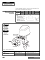
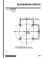
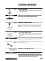
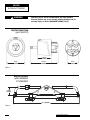
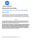
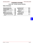
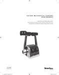
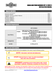
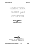
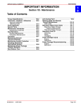
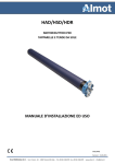
INSTALLATION INSTRUCTIONS
AND OWNER'S MANUAL
w w w. s e a s t a r s o l u t i o n s . c o m
22
TWENTY TWO
ISO 9001
Hydraulic Steering for Outboard
Powered Vessels
Hydraulic Steering for Outboard Powered Boats
Rated to a Maximum of 150HP (Total)
ur way, ay
o
y
it
o
d
u
o
Before y please try it our w
To the Installer and End
User (Owner)
Thank you for choosing SeaStar Steering Systems by SeaStar
Solutions. This Installation and Owner’s Manual contains all the
information that you and others will require for the safe installation
and use of your steering system and MUST remain on board the
boat. Throughout this manual, information for the safe installation
and operation of the steering system will be distinguished in one
of the following ways;
WARNING
Hazards or unsafe practices which could result in severe personal
injury or death.
Failure to adhere to a warning may lead to loss of steering control.
Loss of steering control may result in unpredictable boat behavior,
leading to ejection from boat causing property damage, personal
injury and/or death.
CAUTION
NOTICE
Hazards or unsafe practices which could result in minor injury or
product or property damage.
Important information in regards to installation, use and maintenance
of the steering components.
These safety alerts alone cannot eliminate all of the hazards that may
be present while on the water. SeaStar Solutions recommends
that all users of the steering system take an accredited 'boating
safety course', follow safe boating practices and are made aware
of the environment that they will be in.
BAYSTAR Hydraulics
SAFETY INFORMATION
WARNING
The safety information provided below is intended to inform you of the
dangers that may be present before, during and after the installation.
It is critical that you read and understand ALL the points noted.
The safe operation of the steering system is dependant upon proper
installation and maintenance, common sense, safe judgment and
the knowledge/expertise of the operator. Every installer/user of the
steering system should know the following requirements 'before'
installing/using the steering system.
If you have any questions regarding any of these warnings, contact
SeaStar Solutions.
To reduce risk of severe injury or death. Always wear a Coast Guard
Approved personal flotation device (PFD) and use an engine shut-off
cord (lanyard).
Before installation
Installation
Outboard Powered Vessels
1. Read and understand the Installation and Owner’s Manuals
provided with your steering components.
2. Ensure that all components required to complete the
installation are on hand (including hoses, fittings, oil and the
proper tools required for the installation).
3. SeaStar components are highly engineered and safety tested to
ensure system integrity, DO NOT substitute any component with
non-SeaStar components as this may compromise system
performance/reliability.
1. Install components as directed in all Installation Manuals
(including helm pumps, hoses and fitting kits).
2. DO NOT modify or substitute any component in any way without
written consent from SeaStar Solutions.
3. Comply with all system ratings/regulations (boat/engine, U.S.C.G.).
- Cylinder MUST be compatible with engine(s) installed.
- Cylinder MUST be rated for use on the engine(s) installed.
4. Confirm that there is no interference between the steering cylinder(s),
tiebars and the transom, splashwell, outboard engine or jackplate or
any combination of these parts by performing the following steps;
a) With engine fully tilted DOWN, turn steering wheel from hard over
to hard over and confirm that no interference occurs.
- if using a hydraulic jack plate the above must also be performed
at all the positions of the jack plate.
b) Repeat step 4a) with engines tilted UP.
c) Perform step 4a) with each engine in DOWN/UP positions
confirming that independent TRIM/TILT can be done without
any interference.
5. Confirm that the steering cylinder can be fully stroked in both
directions as well as full tilt and trim without stretching, chafing,
rubbing and/or kinking of the hydraulic hoses.
6. Confirm that extruded nylon tubing has NOT been substituted
for SeaStar Steering Hose.
7. DO NOT use a wire coil type trim switch with a hydraulic steering
system as the wire can wind up tight around the steering wheel
shaft and prevent further steering.
8. Conduct Oil Level and System Check as outlined on page 27 of
this manual.
i
BAYSTAR
HYDRAULIC STEERING
Safety Information Continued
WARNING
Prior to every use
The safety information provided below is intended to inform you of the
dangers that may be present before, during and after the installation.
It is critical that you read and understand ALL the points noted.
1. Check fluid level in highest helm pump (see page 27 for proper
fluid level setting).
2. Verify immediate steering response when turning steering
wheel(s). (Ensure engine turns when steering wheel is turned.)
3. Visually inspect all steering hoses and fittings for wear, kinking
and/or leaks.
4. Check for binding, loose, worn or leaking steering components.
DO NOT OPERATE BOAT IF ANY COMPONENT IS NOT IN PROPER
WORKING CONDITION.
During use
1. WEAR A COAST GUARD-APPROVED PERSONAL FLOTATION
DEVICE (PFD).
2. ATTACH ENGINE SHUT-OFF CORD (LANYARD) TO YOUR PFD.
3. Never allow anyone not familiar with the operation of the
steering system operate the boat at any time.
4. Know and adhere to the operator restrictions for your area
including;
- Federal Laws/Regulations,
- State Laws/Regulations and
- Municipal Laws/Regulations.
DO NOT OPERATE BOAT IF ANY COMPONENT IS NOT IN PROPER
WORKING CONDITION.
After use
Maintenance
1. Rinse off steering system thoroughly using 'fresh, clean water only'.
- Cleaning fluids containing ammonia, acids or any other corrosive
ingredients MUST NOT be used for cleaning any part of the
hydraulic steering system.
1. Maintain steering system at a minimum of twice per year.
- See Routine Maintenance, page 29 of this manual.
Keep our waters clean for all current and future users. Dispose of
ALL fluids in accordance with your local regulations.
ii
BAYSTAR Hydraulics
INTRODUCTION
Before proceeding with the installation, read these instructions
thoroughly. SeaStar Solutions cannot accept responsibility for
installations where instructions have not been followed, where
substitute parts have been used, or where modifications have
been made to our products.
WARNING
NOTICE
WARNING
Do Not use BayStar on vessels that exceed a MAXIMUM horsepower
rating of 150HP (Total), or on smaller HP outboard engines that
use wing nut type transom mount clamping screws. Warranty will
be void if combined with any other product (including SeaStar
steering components). Steering failure may occur causing property
damage and/or personal injury or death.
Due to a small amount of internal hydraulic slip, a “master spoke”
or “centered” steering wheel cannot be maintained with a hydraulic
steering system. For best results, use an equidistant spoke
steering wheel. Maximum steering wheel diameter = 28"(711mm)
and Maximum steering wheel dish = 5"(127mm).
Do Not use a wire coil type trim switch with a hydraulic steering
system. Wire coil can wind tightly around the steering wheel
shaft and prevent further steering!
Index
Safety Information ...................................................................... i
Introduction................................................................................1
Minimum Splashwell Dimensions........................................... 2
Helm Mounting Template............................................................ 3
System Overview ....................................................................... 5
Mounting the Helm .................................................................... 8
Hydraulic Hose/Tube Installation ................................................ 9
NPT Fitting Installation ........................................................ 11
Cylinder Installation ................................................................. 13
Spacer Kit HO5090 ............................................................ 21
Reversing Compact Cylinder Engine Plate .................................. 23
Mounting to Outboard Engines up to 60HP ................................ 24
Filling and Purging the System .................................................. 25
Hydraulic Fluid Requirements ................................................... 25
Oil Level and System Check ................................................ 27
Routine Maintenance ............................................................... 29
Troubleshooting Guide ............................................................. 31
Replacement Parts .................................................................. 33
Warranty ................................................................................. 35
Outboard Powered Vessels
1
BAYSTAR
HYDRAULIC STEERING
Before attempting installation, ensure that the splashwell of your
boat has the following minimum dimensions.
Minimum Splashwell
Dimensions
CYLINDER
MODEL NUMBER
HC4645/47H/
48H/58H
# OF
ENGINES
A
B
C
1
21" (534mm)
6" (153mm)
5" (127mm)
2
Twin engine applications not available at this time
NOTES:
i)
ii)
iii)
iv)
v)
Ensure there is no interference between the
BayStar cylinder rod and the splashwell boot
or engine controls & cables.
Dimensional restrictions also apply
to external motor mount brackets.
Ensure dimension 'A' is maintained through
full trim/tilt range.
Maximum transom thickness 3"(76mm).
Engines less than 70HP may require up to an
additional 1"(25mm) of splashwell clearance.
MIN. ENGINE
CENTER DISTANCE
N/A
A
C
B
CAUTION
Do Not use BayStar
on smaller HP
outboard engines
that use wing nut
type transom mount
clamping screws.
NOTICE
The BayStar system
is a single station
steering system
ONLY, with the option
to add an autopilot
BAYSTAR CYLINDER
(HC4645H SHOWN)
S
P
BAYSTAR
TUBING
S
P
BAYSTAR HELM
Figure 1. Typical Installation Shown.
CYLINDER
HELM PORT CONNECTION
STEERING CYLINDER CONNECTION
HC4645H/47H/48H/58H
(Cylinder is stationary)
Port (P)
Starboard side of cylinder
Starboard (S)
Port Side of cylinder
2
BAYSTAR Hydraulics
HELM MOUNTING TEMPLATE
BayStar Helm
(part# HH4314 & HH4514
BayStar Plus)
Scale 1:1
HELM FLANGE OUTLINE (for reference only)
4-5/8" (118mm) DIA. MAXIMUM COVERAGE, BAYSTAR HELM HH4314
4-1/2" (115mm) DIA. MAXIMUM COVERAGE, BAYSTAR PLUS HELM HH4514
Figure 2.
Outboard Powered Vessels
3
Note: This page left blank intentionally.
4
BAYSTAR Hydraulics
SYSTEM OVERVIEW
HELM
STEP 1
System Installation
• Install helm pump onto dash using the installation instructions noted
on page 8 of this manual.
WARNING
CYLINDER
Ensure that you read and understand ALL cautions, notices and warnings
that are noted in your helm pump installation instructions.
• Install steering cylinder as outlined on page 13 of this manual.
• Install steering hoses as outlined on page 9 of this manual
STEP 2
Filling and Purging Procedure
• Refer to fill and purge procedures as outlined on page 25 of this manual.
NOTE: Power Assist and Catamaran users please use bleeding details
included with your Power Assist or, Liquid Tiebar Installation Instructions.
STEP 3
Oil Level and System Check
• Refer to page 27 of this manual for setting oil level in helm pump and
performing the “system pressure test” to ensure steering system is
ready for use.
WARNING
STEP 4
Oil level and System check is critical to the safe operation of your boat,
failure to follow this important step may lead to loss of steering control
resulting in property damage, personal injury and/or death.
Routine Maintenance
• Refer to page 29 of this manual to become familiar with the routine
maintenance that MUST be carried out in the intervals noted.
BayStar Hydraulic
Steering System
Maximum 150 horsepower (Total).
NOTICE
Specific installation may vary from the application depicted.
Ensure the engine can be fully tilted into the splashwell and
turned from port (engine stop) to starboard (engine stop) without
interference occurring between the steering cylinder and engine
cowling, engine hook and the splashwell or transom.
Outboard Powered Vessels
5
BAYSTAR
HYDRAULIC STEERING
WARNING
Warranty will be void if combined with any other product.
Steering Failure may occur causing property damage and/or
personal injury or death. MAXIMUM 150HP (Total).
BayStar Helm Pump
(part# HH4314)
3-15/16"
(100mm)
4-5/8"
(118mm)
7-15/16"
(200mm)
3" dia.
(76mm)
Figure 3.
BayStar Cylinder
(part# HC4645H/
47H/48H/58H)
2.625"
(67mm)
21" (534mm)
Figure 4.
6
BAYSTAR Hydraulics
BAYSTAR
HYDRAULIC STEERING
Horse Power Limitations
WARNING
Limited to boats rated to a MAXIMUM of 150HP (Total). Twin engine
application not available at this time.
Warranty void if total maximum 150HP (Total) is exceeded.
Tools
You will need the following tools to complete your installation.
• 3" (77mm) diameter hole saw or key hole saw
• 5/16" (9.5mm) drill bit
Wrenches for helm installation
• 1/2" (13mm) for mounting the helm
• 5/8" (16mm) for tube nuts connecting tube to helm pump
Wrenches for HC4645H/47H/48H/58H cylinder installation
• 9/16" (15mm) for tiller bolt (2 required)
• 5/8"(16mm) for shaft nuts and bleed fittings (2 required)
• 11/16" (18mm) for tubing on the cylinder
• 1-1/8" (29mm) for mounting nut
CAUTION
Outboard Powered Vessels
Lightly lubricate threaded fasteners before installing. This will
prevent them from seizing.
Lubricate support rod and all moving parts with a quality marine
grease such as OMC Triple Guard, Quicksilver Anti-corrosion,
Yamaha Marine Grease or equivalent.
Do not remove protective caps from fittings and fitting ports until
hose or tube connections are made. Contaminant's in the steering
system may cause premature wear and/or steering malfunctions.
7
MOUNTING THE HELM
WARNING
Use only self-locking fasteners
provided; substituting non-self
locking fasteners can result in
loosening or separation of equipment and loss of steering control.
DO NOT exceed 110 in.lbs. (12 Nm)
torque on helm nuts and bolts.
CAUTION
Tighten steering wheel shaft nut
before filling and purging the
steering system. Tighten nut to
150 in./lbs. (17 Nm).
DO NOT exceed 200 in.lbs. (22 Nm).
NOTICE
Only use a pipe sealant such as
Loctite® P.S.T. or equivalent on
ALL pipe threads.
DO NOT USE "TAPE" SEALERS.
Figure 5.
Use a pipe sealant such as Loctite P.S.T. or equivalent on all pipe
threads. DO NOT use "tape" sealers.
Step 1:
Determine desired mounting position. Ensure that the steering
wheel will not interfere with other functional equipment. Check for
adequate space behind the dash for fitting and line connections.
Step 2:
Tape the mounting template (found on page 3 of this manual) to
the dash and use a center punch to mark the locations of the hole.
Step 3:
Confirm that you will not be drilling into any other equipment then;
drill the 3” diameter center hole and the four 5/16" diameter
mounting holes as shown on the template.
Step 4:
To simplify installation, we recommend that the fittings being used in
the rear of the helm pump are installed prior to the helm being mounted
to the dash. See NPT fitting installation on page 11 of this manual.
Step 5:
Ensuring that the fill port is in the upper position, install the four
washers and four nuts onto the mounting studs of the helm pump.
Torque nuts to 15 ft. lb.
Step 6:
Lightly grease taper of the helm shaft and mount steering wheel to helm.
WOODRUFF KEY
NOTICE
BayStar HH4314 shown
FILL & VENT PLUG
NUT
HELM PUMP
STEERING WHEEL
WASHER LOCKNUT
8
BAYSTAR Hydraulics
HYDRAULIC HOSE/TUBE
INSTALLATION
Steering hoses/tubing and how they are installed are critical to the safe
operation of your steering system. SeaStar Solutions recommends
the use of BayStar tubing, or, SeaStar hose ONLY. Use of any other
tube/hose may drastically reduce system performance and safety.
WARNING
WARNING
Continuous kinking, rubbing,
chafing or twisting of a steering
hose/tube may eventually
weaken the hose(s) to a point
where it could rupture.
Rupture of a hose will lead to
loss of steering control.
STEP 1
DO NOT cut SeaStar steering hoses, cutting these hoses will
render them useless.
Before continuing on with the installation of your steering hoses,
please ensure that you read and understand the important points
shown below;
• DO NOT install any pipe sealant onto the hose/tube side of a fitting.
• DO NOT remove protective end covers until the hoses/tubing
have been routed and are ready to be connected to the helm
pump, hose/tube fitting or steering cylinder(s).
• Before, during and after installation the hoses/tubing MUST be
protected from chaffing, rubbing, and contact or interference with
assembly screws or sharp edges of any type.
• DO NOT install hoses/tubing in an area where they will be exposed to
high heat, such as engine manifolds, engine compartments or highly
corrosive areas such as battery fumes or electrical connections.
• If possible, route hoses/tubing through a protective PVC cover.
• Secure hose/tube in minimum 2' increments.
• DO NOT bend hoses/tubing tighter than a 3-1/2” (89mm) radius.
• Provide sufficient hose/tube lengths to allow for cylinder movement
throughout the turning arc and UP/DOWN trim/tilt settings of
the engine(s).
• DO NOT allow hoses/tubing to hang free in an area where they
could become a safety hazard.
• Where possible, route hoses in an area where they can be easily
inspected for wear on a regular basis.
Set Up
• See Figure 8 to locate your plumbing diagram.
• Mark each end of the hose to ensure proper connection.
NOTICE
Hoses/tubing is crossed from the helm pump(s) to the steering
cylinder(s). Port side helm connection will be installed onto the
starboard fitting on the cylinder, and the starboard side helm
connection will be installed onto the port side fitting on the cylinder.
STEP 2
Routing
Throughout the hose/tube installation, ensure the protective caps
remain installed onto the end of the hoses. Doing so will prevent
contamination from entering the system.
• Route steering hoses/tubing so that the hose bend restrictor
will be located at the steering cylinder(s).
• Route steering hoses/tubing so that they have a gradual rise
from the steering cylinder(s) to the helm pump.
Outboard Powered Vessels
9
BAYSTAR
HYDRAULIC STEERING
• If routing hoses hoses/tubing a blind area, ensure that the area
is free and clear of any sharp edge, screw or any other object
that may damage the hose.
• Secure hoses/tubing every 2’.
Substituting brass fittings into the steering cylinder may result in
galvanic corrosion and irreparable damage to the cylinder as well
as affect system integrity.
1. Minimum bend radius 3-1/2"
(89mm).
2. DO NOT adjust angle of
fittings without first
consulting manufacturer.
3. Hoses should be secured to
the control cable harness as
they enter the splashwell
through the boot.
1
2
3
Figure 6.
STEP 3A
BayStar Tubing Installation
• Remove protective covers
• Install tube end “complete with the swage fitting and protective
covering” onto the proper steering cylinder tube fitting, tighten
hand-tight
• While holding fitting with a wrench, tighten to 15 ft-lb
• Route tubing to helm pump
• Remove protective cover
• Using a pipe cutter, cut off excess tubing
• Slide tube nut over tubing
• Push tubing into bottom of component fitting
• Hand tighten tube nut
• While holding fitting with a wrench, tighten tube nut to 12 ft-lb.
COMPONENT FITTING
TUBE NUT
BAYSTAR TUBING
Figure 7.
10
DO NOT USE PIPE SEALANT HERE
BAYSTAR Hydraulics
BAYSTAR
HYDRAULIC STEERING
STEP 3B
SeaStar hose to fitting installation
• Remove protective covers.
• Install hose end fitting onto intended fitting, tighten hand tight.
• While holding the receiving fitting with a wrench, tighten hose fitting
to 15ft-lb.
WARNING
When installed, confirm that the hoses are not being pulled or
kinked over by pushing the engine(s) back and fourth. Hoses
must NOT be pulled on at any time.
SINGLE FRONT MOUNT
Figure 8.
Hose Inspection
DO NOT operate the vessel if ANY of the following are observed:
• Fitting slippage on hose
• Damaged, cracked, cut or abraded cover (or any reinforcement
exposed)
• Hard, stiff, heat cracked, or charred hoses;
• Cracked, damaged, or badly corroded fittings;
• Leaks at fitting, or in hose;
• Kinked, crushed, flattened or twisted hose; and
• Blistered, soft, degraded, or loose cover.
NPT Fitting
Installations
ONLY
Apply a liquid, Teflon based pipe sealant onto the threads going into
a helm pump and/or steering cylinder. Tighten fitting "hand-tight".
Using a wrench tighten an additional 1–1/2 turns. Continue to
tighten until desired orientation is met.
Outboard Powered Vessels
11
BAYSTAR
HYDRAULIC STEERING
12
BAYSTAR Hydraulics
CYLINDER INSTALLATION
BayStar Compact Cylinders, HC4645H,
HC4647H, HC4648H and HC4658H.
On the following pages of this instruction booklet you will find the
assembly drawing for your specific application.
WARNING
NOTICE
CAUTION
Single Engines
WARNING
Refer to page 30 for the correct
torque specifications for your
installation. Failure to correctly
install your steering cylinder and
torque all screws may result in
steering failure causing property
damage and/or personal injury.
CAUTION
Outboard Powered Vessels
In some cases, engine manufacturers will install plugs, caps
and/or screws into the engine tiller arm. These plugs, caps
and/or screws MUST be removed prior to installation of the
steering cylinder. Failure to do so may cause wear on steering
parts leading to property damage and/or personal injury or death.
Before beginning installation make sure that all mounting
hardware is included and that the tiller arm and the tilt tube bolt
holes are clean and free from rust or burrs.
Engines with rigid engine mounts have been shown to cause
premature wear to the pivot cylinder — therefore, please perform a
complete Inspection of your steering system as outlined in the
Maintenance Section at the back of this manual.
Step 1:
Using a good quality marine grease (such as Evinrude Triple Guard,
Quicksilver anti-corrosion, Yamaha marine grease, or equivalent),
liberally lubricate the tilt tube, support rods (Item 5) and mount nut
(item 7) and then slide the support rods (item 5) into engine tilt tube.
Step 2:
Lightly grease the tiller bolt (Item 2) & partially screw into the appropriate
hole in the tiller arm to assure a proper fit. Remove and go to Step 3.
Step 3:
Select appropriate insert diagram from Figure 9 through 15 to determine
proper orientation of the cylinder assembly, the tiller bolt and the selflocking nut (Items 8, 2 and 1). Grease and install as indicated.
Step 4:
Screw lubricated mounting nut (item 7) onto tilt tube of the engine.
Torque nut 20–25 ft-lb.
Step 5:
Lightly grease the ends of the cylinder shaft and holes of the support
rods (item 5). Attach and secure support rods (Item 5) to the cylinder
shaft. Tighten using the nuts and washers (Items 4 & 3) as illustrated
in Figure 9 through 15.
If installing a jack plate make sure that there isn't any interference
between the jack plate and your steering cylinder. If there is
interference, it may occur during full tilt and you should install lift
restrictors (Tilt Stop Switch). Some engine manufacturers supply
these as standard equipment.
13
BAYSTAR
HYDRAULIC STEERING
ENGINE
MANUFACTURER
FORCE
HONDA
WARNING
Refer to page 30 for correct torque specifications of all installation hardware.
YEAR
MODEL
CYLINDER
NOTE
1985 TO 1994
1995 TO DATE
1992 TO DATE
90–150 HP
90–120 HP
30–50 HP
HC4645H
HC4645H
HC4645H
(See Fig. 9a)
1996 TO DATE
1998 TO 2010
2003 TO DATE
2010 TO DATE
75–90 HP
115–130 HP
135–150 HP
115 HP
HC4645H
HC4647H
HC4645H
HC4645H
Cylinder may not be centered when mounted due to short
tiller tube (See Fig. 9b)
(See page 15)
Figure 9.
WARNING
In some cases, engine manufacturers will install
plugs, caps and/or screws into the engine tiller
arm. These plugs, caps and/or screws MUST be
removed prior to installation of the steering
cylinder. Failure to do so may cause wear on
steering parts leading to property damage and/or
personal injury or death.
2*
21 ft-lb
5
7*
20-25ft-lb
4*
5
33ft-lb
3
Figure 9b
3
33ft-lb
9
4*
6
1*
May have to cut off
part of transom
hangers if
cylinder
assembly
interferes
when
motor is tilted
to trailer lock
position.
PART #
*1
*2
3
*4
5
113529
113222
731625
731720
590040
14
21ft-lb
WARNING
Fully tilting the engine may cause the steering cylinder to interfere with the
transom and/or splashwell. Possible damage to the steering system can
result. Ensure that the cylinder is free from interference at all times.
NOTICE
Force 90-150HP 1985 to 1994
ITEM
8
9
Figure 9a
Small and mid-sized outboards, up to 60HP may use a shorter tilt tube;
this will cause the cylinder to not be centered. Refer to page 24 for
aligning details.
QTY DESCRIPTION
1
1
2
2
2
Nut, 3/8" NF Nylok® SS
HHCS 3/8" NF x 1-1/4" SS
Washer Flat, 7/16" SS
7/16" NF Nylok® SS
Support Bracket
Honda 1992 To Date
30–50 HP
* Refer to page 30 for correct torque specifications.
ITEM
6
*7
8
9
PART #
N/A
N/A
HC46xxH
HF4202
QTY DESCRIPTION
1
1
1
1
Clip, Support Bracket
Mount Nut, Support Bracket
Cylinder Assembly
Bleed Fitting Kit, 2 fittings per kit
BAYSTAR Hydraulics
BAYSTAR
WARNING
HYDRAULIC STEERING
Refer to page 30 for correct torque specifications of all installation hardware.
ENGINE
MANUFACTURER
YEAR
MODEL
CYLINDER
HONDA
1998 TO 2010
115–130 HP
HC4647H
NOTE
Figure 10.
WARNING
In some cases, engine manufacturers will install
plugs, caps and/or screws into the engine tiller arm.
These plugs, caps and/or screws MUST be removed
prior to installation of the steering cylinder. Failure to
do so may cause wear on steering parts leading to
property damage and/or personal injury or death.
WARNING
Fully tilting the engine may cause the steering
cylinder to interfere with the transom and/or
splashwell. Possible damage to the steering system
can result. Ensure that the cylinder is free from
interference at all times.
NOTICE
Small and mid-sized outboards, up to 60HP may use
a shorter tilt tube; this will cause the cylinder to not
be centered. Refer to page 24 for aligning details.
2*
21ft-lb
5
7*
20-25ft-lb
4*
33ft-lb
5
3
3
33ft-lb
4*
9
6
8
9
1*
21ft-lb
* Refer to page 30 for correct torque specifications.
ITEM
PART #
*1
*2
3
*4
5
6
113529
113222
731625
731720
590040
N/A
QTY DESCRIPTION
1
1
2
2
2
1
Outboard Powered Vessels
Nut, 3/8" NF Nylok® SS
HHCS 3/8" NF x 1-1/4" SS
Washer Flat, 7/16" SS
7/16" NF Nylok® SS
Support Bracket
Clip, Support Bracket
ITEM
*7
8
9
PART #
N/A
HC4647H
HF4202
QTY DESCRIPTION
1
1
1
Mount Nut, Support Bracket
Cylinder Assembly
Bleed Fitting Kit, 2 fittings per kit
15
BAYSTAR
HYDRAULIC STEERING
ENGINE
MANUFACTURER
WARNING
Refer to page 30 for correct torque specifications of all installation hardware.
YEAR
MODEL
CYLINDER
NOTE
1984-TO 1989
1990-TO DATE
1998-TO DATE
75-150 HP
75-150 HP
40-60 HP
HC4645H
HC4645H
HC4645H
(See Fig. 11a)
2002-TO DATE
90-115HP
HC4645H
NISSAN
1990-TO DATE
120-140 HP
HC4645H
TOHATSU
1990-TO DATE
120-140 HP
HC4645H
MERCURY/MARINER
Figure 11a.
Cylinder may not be centered when mounted due to short
tiller tube (See Fig. 11b)
(See Fig. 11c)
Figure 11b.
WARNING
In some cases, engine manufacturers will install
plugs, caps and/or screws into the engine tiller
arm. These plugs, caps and/or screws MUST be
removed prior to installation of the steering
cylinder. Failure to do so may cause wear on
steering parts leading to property damage and/or
personal injury or death.
NOTICE
Small and mid-sized outboards, up to 60HP may
use a shorter tilt tube; this will cause the
cylinder to not be centered. Refer to page 24
for aligning details.
SPACER MAY
BE REQUIRED
Mercury/Mariner
1984 to 1989
Mercury 1998 to
Date 40 to 60HP
2*
Figure 11c.
21ft-lb
5
4*
7*
33ft-lb
20-25ft-lb
5
3
3
9
Mercury/Mariner
2002 to Date
90 to 115HP
6
4*
33ft-lb
Figure 11.
ITEM
PART #
*1
*2
3
*4
5
6
113529
113222
731625
731720
590040
N/A
16
8
1*
9
21ft-lb
* Refer to page 30 for correct torque specifications.
QTY DESCRIPTION
1
1
2
2
2
1
Nut, 3/8" NF Nylok® SS
HHCS 3/8" NF x 1-1/4" SS
Washer Flat, 7/16" SS
7/16" NF Nylok® SS
Support Bracket
Clip, Support Bracket
ITEM
*7
8
9
PART #
N/A
HC46xxH
HF4202
QTY DESCRIPTION
1
1
1
Mount Nut, Support Bracket
Cylinder Assembly
Bleed Fitting Kit, 2 fittings per kit
BAYSTAR Hydraulics
BAYSTAR
WARNING
HYDRAULIC STEERING
Refer to page 30 for correct torque specifications of all installation hardware.
ENGINE
MANUFACTURER
JOHNSON/EVINRUDE
JOHNSON/EVINRUDE
JOHNSON/EVINRUDE
YEAR
MODEL
CYLINDER
NOTE
1977 TO 1990
1991 TO DATE
1997 TO DATE
65–150 HP
40–150 HP
115 HP FICHT
HC4648H
HC4645H
HC4658H
Refer to Figure 12d
Refer to Figure 12a
If using cylinder HC4645H please invert pivot plate
(See Page 23). Refer to Figure 12c
1997 TO DATE
1998 TO DATE
75-150 HP FICHT
40–140 HP 4 Stroke
HC4645H
HC4658H
Requires Spacer Kit H05090 (See Page 21)
If using cylinder HC4645H please invert pivot plate
(See Page 23). Refer to Figure 12b
Figure 12a.
Figure 12c.
Figure 12d.
Johnson/Evinrude
1991 to Date
40-70HP
Johnson/Evinrude
1997 to Date
115 HP FICHT
Johnson/Evinrude
1977 to 1990
65-150HP
Figure 12b.
3
1*
21ft-lb
7*
20-25ft-lb
4*
5
33ft-lb
3
Johnson/Evinrude
1998 to Date
40–140 HP
4-Stroke
5
6
2*
4*
33ft-lb
WARNING
In some cases, engine manufacturers will install plugs, caps and/or
screws into the engine tiller arm. These plugs, caps and/or screws MUST
be removed prior to installation of the steering cylinder. Failure to do so
may cause wear on steering parts leading to property damage and/or
personal injury or death.
PART #
*1
*2
3
*4
5
113529
113222
731625
731720
590040
21ft-lb
8
9
NOTICE
Small and mid-sized outboards, up to 60HP may use a
shorter tilt tube; this will cause the cylinder to not be
centered. Refer to page 24 for aligning details.
* Refer to page 30 for correct torque specifications.
Figure 12.
ITEM
9
QTY DESCRIPTION
1
1
2
2
2
Outboard Powered Vessels
Nut, 3/8" NF Nylok® SS
HHCS 3/8" NF x 1-1/4" SS
Washer Flat, 7/16" SS
7/16" NF Nylok® SS
Support Bracket
ITEM
6
*7
8
9
PART #
N/A
N/A
HC46xxH
HF4202
QTY DESCRIPTION
1
1
1
1
Clip, Support Bracket
Mount Nut, Support Bracket
Cylinder Assembly
Bleed Fitting Kit, 2 fittings per kit
17
BAYSTAR
HYDRAULIC STEERING
ENGINE
MANUFACTURER
YAMAHA
WARNING
Refer to page 30 for correct torque specifications of all installation hardware.
YEAR
MODEL
CYLINDER
NOTE
1986 TO DATE
1997 TO DATE
2002 TO DATE
100–150 HP 2 Stroke HC4645H
F75–F150 HP
HC4645H
25–70 HP 4 Stroke
HC4648H
(See Fig. 13b)
(See Fig. 13b)
Requires Spacer Kit H05090 (See Page 21).
Figure 13b.
Figure 13a.
WARNING
In some cases, engine manufacturers will
install plugs, caps and/or screws into the
engine tiller arm. These plugs, caps and/or
screws MUST be removed prior to
installation of the steering cylinder. Failure
to do so may cause wear on steering parts
leading to property damage and/or personal
injury or death.
Yamaha 1986 To Date
40–60 HP
Yamaha 1997 To Date
80–150HP, 4 Stroke
Yamaha 1998 To Date
40–60 HP
Yamaha 1997 To Date
5
3
1*
21ft-lb
7*
20-25ft-lb
4*
5
9
33ft-lb
3
6
NOTICE
4*
33ft-lb
8
WARNING
Figure 13.
ITEM
PART #
*1
*2
113529
113330
Engine clamp brackets must be modified
(cut or ground) and the engine through
bolted onto transom or interference will
occur restricting engine trim & tilt.
QTY DESCRIPTION
1
1
Nut, 3/8" NF Nylok® SS
HHCS 3/8" NF x 1-3/8" SS
If spacer kit HO5090 used then:
3
*4
5
18
198461
731625
731720
590040
1
2
2
2
HHCS 3/8" NF x 1-5/8" SS (In Kit)
Washer Flat, 7/16" SS
7/16" NF Nylok® SS
Support Bracket
2*
9
21ft-lb
Small and mid-sized outboards,
up to 60HP may use a shorter tilt
tube; this will cause the cylinder
to not be centered. Refer to
page 24 for aligning details.
* Refer to page 30 for correct torque specifications.
ITEM
6
*7
8
9
PART #
N/A
N/A
HC46xxH
HF4202
QTY DESCRIPTION
1
1
1
1
Clip, Support Bracket
Mount Nut, Support Bracket
Cylinder Assembly
Bleed Fitting Kit, 2 fittings per kit
BAYSTAR Hydraulics
BAYSTAR
HYDRAULIC STEERING
Refer to page 30 for correct torque specifications of all installation hardware.
WARNING
ENGINE
MANUFACTURER
YEAR
MODEL
CYLINDER
NOTE
YANMAR
1990 TO DATE
27–36 HP
HC4645H
Requires Spacer Kit HO5090 (See Page 21).
WARNING
In some cases, engine manufacturers will install
plugs, caps and/or screws into the engine tiller
arm. These plugs, caps and/or screws MUST be
removed prior to installation of the steering
cylinder. Failure to do so may cause wear on
steering parts leading to property damage and/or
personal injury or death.
NOTICE
Small and mid-sized outboards, up to 60HP may
use a shorter tilt tube; this will cause the
cylinder to not be centered. Refer to page 24
for aligning details.
5
1*
21ft-lb
7*
20-25ft-lb
4*
5
33ft-lb
3
3
6
4*
9
33ft-lb
8
9
2*
Figure 14.
ITEM
PART #
*1
*2
113529
113222
* Refer to page 30 for correct torque specifications.
QTY DESCRIPTION
1
1
Nut, 3/8" NF Nylok® SS
HHCS 3/8" NF x 1-1/4" SS
If spacer kit HO5090 used then:
3
*4
5
198461
731625
731720
590040
21ft-lb
1
2
2
2
Outboard Powered Vessels
HHCS 3/8" NF x 1-5/8" SS (In Kit)
Washer Flat, 7/16" SS
7/16" NF Nylok® SS
Support Bracket
ITEM
6
*7
8
9
PART #
N/A
N/A
HC46xxH
HF4202
QTY DESCRIPTION
1
1
1
1
Clip, Support Bracket
Mount Nut, Support Bracket
Cylinder Assembly
Bleed Fitting Kit, 2 fittings per kit
19
BAYSTAR
HYDRAULIC STEERING
ENGINE
MANUFACTURER
SUZUKI
WARNING
Refer to page 30 for correct torque specifications of all installation hardware.
YEAR
MODEL
CYLINDER
1986 TO DATE
1996 ONLY
1987 TO 2002
1990 TO 2000
1998 TO DATE
2001 TO DATE
150 HP
115–140 HP
115–140 HP
90–100 HP
40–70 HP 4 Stroke
115–140 HP 4 Stroke
HC4645H
See Note
HC4645H
HC4645H
HC4645H
HC4658H
NOTE
(See Fig. 15c)
Consult Factory
Requires Spacer Kit HO5090 (See Figs. 15a & 15b)
Requires Spacer Kit HO5090 (See Page 21).
Requires Spacer Kit HO5090 (See Page 21).
If using cylinder HC4645H please invert pivot plate
(See Page 23). (Refer to Fig. 15d).
Figure 15.
†
NOTICE
For ALL Suzuki 40-140 HP 4 stroke use
tiller bolt supplied in spacer kit HO5090.
* Refer to page 30 for correct
torque specifications.
Small and mid-sized
outboards, up to 60HP
may use a shorter tilt
tube; this will cause
the cylinder to not be
centered. Refer to
page 24 for aligning
details.
5
21ft-lb
7*
20-25ft-lb
4*
Figure 15a.
5
9
WARNING
6
4*
8
33ft-lb
2*
Figure 15c.
Figure 15b.
*1
*2
113529
113222
Suzuki 1986 to Date
150HP
Suzuki 2001 to Date
115-140 HP 4 Stroke
QTY DESCRIPTION
1
1
Nut, 3/8" NF Nylok® SS
HHCS 3/8" NF x 1-1/4" SS
If spacer kit HO5090 used then:
3
*4
20
198461
731625
731720
Fully tilting the engine may
cause the steering cylinder to
interfere with the transom
and/or splashwell. Possible
damage to the steering system
can result. Ensure that the
cylinder is free from
interference at all times.
WARNING
Suzuki 115/140 to 1998
PART #
21ft-lb
Figure 15d.
May have to cut off
part of transom
hangers if
cylinder
assembly
interferes
when
motor is tilted
to trailer lock
position.
ITEM
33ft-lb
9
3
Suzuki 115-140HP
(use rear hole)
3
1*
1
2
2
HHCS 3/8" NF x 1-5/8" SS (In Kit)
Washer Flat, 7/16" SS
7/16" NF Nylok® SS
ITEM
5
6
*7
8
9
In some cases, engine manufacturers will install
plugs, caps and/or screws into the engine tiller
arm. These plugs, caps and/or screws MUST be
removed prior to installation of the steering
cylinder. Failure to do so may cause wear on
steering parts leading to property damage and/or
personal injury or death.
PART #
590040
N/A
N/A
HC46xxH
HF4202
QTY DESCRIPTION
2
1
1
1
1
Support Bracket
Clip, Support Bracket
Mount Nut, Support Bracket
Cylinder Assembly
Bleed Fitting Kit, 2 fittings per kit
BAYSTAR Hydraulics
BAYSTAR
HO5090 Spacer Kit
HYDRAULIC STEERING
For Use with BayStar Hydraulic Steering Cylinder HC4645H,
HC4647H, HC4648H and HC4658H.
JOHNSON/EVINRUDE,
1998 to DATE 40–140 HP 4 Stroke
SUZUKI
2001 to DATE 115–140 HP 4 Stroke
Fig. 16.
SUZUKI
1998 to DATE 115-140 HP
Fig. 18.
2
2
1
SUZUKI
1
Figure 16.
1998 to DATE 40 & 70 HP
Fig. 17.
Figure 18.
YAMAHA
1990 to DATE 70–90 HP
Fig. 19.
2002 to DATE 25–70 HP 4 Stroke
YANMAR
1990 to DATE 27–36 HP
4 Stroke
Fig. 19.
1
4
2
3
Figure 17.
Figure 19.
WARNING
In some cases, engine manufacturers will install plugs, caps and/or screws into the engine tiller arm. These plugs, caps and/or screws MUST
be removed prior to installation of the steering cylinder. Failure to do so may cause wear on steering parts leading to property damage and/or
personal injury or death.
WARNING
Refer to page 30 for correct torque specifications of all installation hardware.
ITEM
*1
2
3
4
PART #
688726
113600
113330
773421
QTY
1
1
1
1
DESCRIPTION
ITEM
PART #
QTY
DESCRIPTION
HHCS 3/8" NF x 2-1/4" SS (Tiller Bolt)
SS Fender Washer
HHCS 3/8" NF x 1-3/8" SS
Aluminum Spacer, 1/2"
Outboard Powered Vessels
21
BAYSTAR
HYDRAULIC STEERING
22
BAYSTAR Hydraulics
REVERSING COMPACT
CYLINDER ENGINE PLATE
Recommended Tools
5/32" Allen head socket, with extension.
1. DO NOT attempt to reverse the pivot plate with the cylinder
installed on the engine. (This may damage the steering shaft,
causing irreparable damage.)
2. Remove the two cap screws from one end of the steering cylinder
using the 5/32" Allen head wrench, or socket.
CAUTION
DO NOT pull the gland off the end of the shaft, doing so may
damage the seals when you try to reassemble it.
3. Remove the pivot plate and flip over end for end, placing the end
hole over the shaft stub on the fixed gland.
CAUTION
4. After removing the cap screws there will be small amounts of
debris on the screw. Ensure that any loose debris is removed
from inside and the face of the cylinder body.
5. Carefully slide the loose gland back into place so that the gland
stub fits into the hole on the pivot plate. Some SeaStar steering
fluid applied to the O-ring on the gland may ease reinsertion into
the barrel.
6. Align the screw holes on the gland with the threaded holes on the
barrel, ensure that the gland face is butted tightly against the end
of the barrel, with no debris in between, and fasten using the cap
screws removed earlier. Tighten to torque spec 60 in-lb (5 ft-lb).
PIVOT PLATE
END GLAND
BARREL
SHAFT
CAP SCREW
Figure 20.
Outboard Powered Vessels
23
MOUNTING TO OUTBOARD
ENGINES UP TO 60 HP
Small and mid sized outboard engines up to 60HP may use a
shorter tilt tube causing the BayStar Compact Steering Cylinder to
be NOT centered with the engine in the straight ahead position.
This will create reduced steering articulation in one direction.
Please follow the instructions below to center the cylinder and
address this issue.
Centering Instructions
1. Mount the steering cylinder as per your installation manual and
position the engine in the straight ahead position.
2. Using a measuring tape, measure the amount of steering rod
on both sides of the steering cylinders. (Refer to Figure 21.)
If the starboard side of the rod is shorter than the port side by
11/16" or more, proceed to Step 3. If less than 11/16" your
cylinder is centered, continue on with steering installation as
per your installation manual.
3. Remove the support rod mounting nut (item 1), the cylinder
end nut (item 2), then remove the support rod assembly.
4. Carefully remove the support rod retaining clip (item 3) using a
vice, and move the clip to the inner groove (item 4).
5. Reinstall the support rod assembly and verify that the measurements
taken in Step 2 are now within 11/16" side to side.
6. Continue with steering system installation as per the installation
manual that was provided with your steering system.
1
4
2
MEASURE THESE DISTANCES
WITH MEASURING TAPE
3
Figure 21.
24
BAYSTAR Hydraulics
FILLING AND PURGING
THE SYSTEM
DEALER NOTICE
Reduce purging time to approximately 10 min per system with optional,
portable Power Purge Jr. For more information reference our Website
at www.seastarsolutions.com or contact your marine parts dealer.
Read First
This procedure requires two people. One person may not be able
to remove all the air from the system which will result in spongy,
unresponsive steering.
During the entire filling procedure, oil must be visible in the filler tube.
Do not allow the oil level to disappear into the helm pump, as this
may introduce air into the system and increase your filling time.
Hydraulic Fluid
Requirements
Recommended oils for your BayStar Steering System are;
SeaStar/BayStar Marine Steering Fluid, part# HA5430 (1 quart),
HA5440 (1 Gallon.)
Texaco HO15
Chevron Aviation Fluid A
Aero Shell Fluid #41
Mobil Aero HFA
Esso Univis N15
Fluids meeting Mil H5606 specifications.
Automatic transmission fluid Dexron ll may be used in an emergency.
In case of emergency any non-toxic, non-flammable fluid may provide
temporary steering. Steering system should be fully serviced after
such usage. Please contact manufacturer.
WARNING
NEVER use brake fluid. Any
non-approved fluid may cause
irreparable damage, loss of
steering, and cancellation
of warranty.
NOTICE
NOTICE
Oil can be re-used if filtered through a fine mesh screen such as used
for gasoline. If unable to filter oil, an additional bottle of oil is required.
"Bleeder" refers to cylinder fitted with bleeder tee fittings. Open bleeder
by turning bleed nipple tube nut 2 revolutions counter clockwise.
NOTICE
PUSH PIN
Filling the helm with oil can be
done faster if oil is poured into
the helm prior to connecting filler
tube and oil bottle to the helm.
Part #HA5438.
FILLER PLUG
(REMOVED)
FILLER KIT
HELM FILL
PORT
DO NOT LET
OIL LEVEL
FALL BELOW
THIS POINT
Figure 22.
NOTICE
Outboard Powered Vessels
Help protect your boating environment by ensuring that all used oil
is disposed of properly.
25
BAYSTAR
HYDRAULIC STEERING
Step 1
OIL BOTTLE
FILLER TUBE
HELM
STEERING
WHEEL
HC4645H
CYLINDER
Step 2
TURN
CLOCKWISE
• Screw the threaded end of the filler tube into the helm filler port.
• Remove the cap from the oil bottle and holding upright screw into the
filler tube bottle cap. Poke hole in the bottom of the bottle.
• Fill the helm pump with hydraulic oil so that it is visible in the filler tube.
Oil should always be visible in the filler tube. Use the next bottle of
fluid at any time during the procedure in order to maintain the oil
level. Do not proceed with step 2 until helm is full.
• Turn the steering wheel clockwise until the cylinder rod is fully
extended.
• Open starboard side fitting.
OPEN
STARBOARD
SIDE
BLEEDER
Step 3
TURN
COUNTERCLOCKWISE
CLOSE
STARBOARD
SIDE
BLEEDER
Step 4
• Hold the cylinder body to prevent the rod from moving and turn
the wheel counter-clockwise until a steady stream of air free oil
flows from the bleeder nipple.
Note: If attached to engine, hold engine to prevent cylinder rod
from moving.
• While continuing to turn the wheel, close the bleeder fitting.
• Continue to turn the steering wheel counter-clockwise until the
cylinder rod is fully extended. (Steering wheel will come to a stop.)
• Open Port side bleeder.
TURN
COUNTERCLOCKWISE
OPEN
PORT SIDE
BLEEDER
Step 5
TURN CLOCKWISE
CLOSE
PORT SIDE
BLEEDER
26
• Hold the cylinder body to prevent the rod from moving a turn the
wheel clockwise until a steady stream of air free oil flows from
the bleeder nipple.
Note: If attached to engine, hold engine to prevent cylinder rod
from moving.
• While continuing to turn the wheel, close the port side bleeder
fitting.
BAYSTAR Hydraulics
BAYSTAR
HYDRAULIC STEERING
System Air Test
• Place engine in the center position.
• Manually push engine back and fourth.
• While pushing engine back and fourth, watch the steering cylinder
"body" move.
If cylinder body moves more than 1/8", this is a sign that there is still
air remaining in the system and further bleeding is required.
WARNING
DO NOT use SeaStar Power Purge SR. with the BayStar Steering
system unless pressure gauge kit# HA5443 has been installed.
Failure to do so may result in damage to the steering system.
Oil Level and System Check
WARNING
Step 1 – Oil level Setting
The oil level MUST be checked and maintained
BEFORE EACH use to ensure safe steering operation. Failure to
adhere to this warning may lead to loss of steering control resulting
in persons being ejected from vessel or collision with an obstacle,
leading to property damage, personal injury and/or death.
CAUTION
Side mount and Splashwell mount cylinder are unbalanced. To set
the oil level in the helm pump the cylinder rod MUST be fully
“retracted (cylinder shaft all the way in the cylinder body). Failure to
adhere to this caution WILL result in oil spillage at the helm filler
port and/or stiff steering operation.
• For helms mounted with the wheel shaft completely horizontal
MUST be filled to the bottom of filler hole AT ALL TIMES. DO
NOT allow oil level to drop more than 1/4” below filler threads.
• For helms mounted on a 20 degree angle, or, with wheel shaft in
the vertical position, oil level should be within 1/2” of filler hole.
Step 2 – System Check
WARNING
The system check MUST be completed after
installation. Doing so will ensure the safe operation of your
steering system and will any fault/leak will show at this time.
Failure to adhere to this warning/check may result in the loss of
steering control leading to ejection from the vessel, or, collision
with an obstacle resulting in property damage, personal injury
and/or death.
• Turn steering wheel hard over to hard over to confirm unrestricted
movement of the steering system and hoses. Repeat this
procedure in ALL trim/tilt positions of the engine(s). If interference
occurs, or, hoses are being stretched this MUST be removed
prior to operating your boat.
• Confirm that engine(s) are deflecting to the proper direction
when steering wheel is turned.
Outboard Powered Vessels
27
BAYSTAR
HYDRAULIC STEERING
• If no interference is noticed, or, any interference is corrected,
go to next step.
• Take steering wheel hard over to starboard (any helm can be used
on a multi-station boat). Once the wheel reaches its stop point
(cylinder is fully stroked out), continue to force the wheel one (1)
full turn past stop. Leave wheel in this position while you check
all PORT side connections, fittings, seals and hoses for leaks.
NOTICE
This step will NOT harm the system and any noise
made during this step should not be considered a fault in the
steering system.
• If leaks are noticed they MUST be repaired prior to operating boat.
After repair repeat bleeding procedures as outlined in this manual.
• Repeat to the Port direction and inspect ALL starboard side
connections, fittings, seals and hoses for leaks.
NOTICE
This step will NOT harm the system and any noise
made during this step should not be considered a fault in the
steering system.
• If leaks are noticed they MUST be repaired prior to operating boat.
After repair repeat bleeding procedures as outlined in this manual.
WARNING
28
Failure to complete the above noted step or, failure to correct a
problem may result in loss of steering control leading to ejection
from the vessel or collision with an obstacle resulting in property
damage, personal injury and/or death.
BAYSTAR Hydraulics
ROUTINE MAINTENANCE
WARNING
Following the routine maintenance schedules as outlined below,
in the time frame noted will ensure years of service from your
SeaStar Steering System, as well as keep you and your passengers
safe from the dangers that are present on and off the water.
1. Owner(s) (End Users)
Prior to every use.
1. Check Fluid level in highest helm pump (see page 27 for proper
fluid level setting).
2. Verify immediate steering response when turning steering
wheel(s).(Ensure engine turns when steering wheel is turned.)
3. Visually inspect all steering hoses and fittings for wear, kinking
and/or leaks.
4. Check for binding, loose, worn or leaking steering components.
WARNING
DO NOT operate boat if any
component is not in proper
working condition.
2. Qualified Marine
Mechanic
WARNING
Any work being performed with
the steering system MUST be
completed by a qualified
mechanic with the working
knowledge of the system.
After first 20 hours, then every 100 hours or 6 months thereafter
(which ever comes first).
1. All points noted above.
2. Check tightness of ALL fasteners/fittings throughout the steering
system. Tighten to correct torque specifications as required.
3. Check for mechanical play or slop throughout steering system,
correct as required.
4. Check for signs of corrosion. If corrosion is present contact your
dealer or SeaStar Solutions.
After every 200 hours or 12 months (which ever comes first).
1. All points noted above.
2. Remove support rod from engine steering/tilt tube. Clean engine
steering/tilt tube and re-grease using a good quality marine grease.
3. Grease support rod liberally
4. Grease all contact points shown in Figure 23. DO NOT remove
tiller bolt to re-grease.
5. Remove steering wheel and re-grease wheel shaft using a good
quality marine grease.
6. Inspect hydraulic oil for cleanliness, flush if required.
GREASE POINTS
1
2
1
4
3
3
Figure 23.
1. Remove support rod completely; clean engine steering/tilt tube.
and regrease with a good quality marine grease. Complete on
both sides of cylinder.
NOTE: Ensure proper torque specification is met when reinstalling.
Outboard Powered Vessels
29
2. Remove tiller nut; clean threads, regrease using a good quality
marine grease, then reinstall.
NOTE: Ensure proper torque specification is met when reinstalling.
3. Remove support rod from cylinder shaft, clean and regrease
using a good quality marine grease.
NOTE: Ensure proper torque specification is met when reinstalling.
4
Figure 24. HH4314 Shown.
4. Remove steering wheel; clean off helm pump shaft; regrease
using a good quality marine grease .
NOTE: when reinstalling steering wheel, ensure proper torque
specification is met.
Bolt Torque Specifications
Values are stated in: in/lbs (N.m)
Bolt Size
2-56
2-64
3-48
3-56
4-40
4-48
5-40
5-44
18-8SS
2.5 (.282)
3.0 (.338)
3.9 (.440)
4.4 (.497)
5.2 (.587)
6.6 (.740)
7.7 (.869)
9.4 (1.06)
Brass
2.0 (.226)
2.5 (.282)
3.2 (.361)
3.6 (.407)
4.3 (.486)
5.4 (.610)
6.3 (.712)
7.7 (.869)
Values are stated in: ft/lbs (N.m)
Bolt Size
7/16"-14
7/16"-20
1/2"-13
1/2"-20
9/16"-12
9/16"-18
NOTICE
30
18-8SS
31.0 (42.00)
33.0 (44.74)
43.0 (58.30)
45.0 (61.01)
57.0 (77.28)
63.0 (85.42)
Brass
26.0 (35.25)
27.0 (36.61)
35.0 (47.45)
37.0 (50.17)
47.0 (63.72)
51.0 (69.15)
These are the recommended maximum torque values for reusable dry
bolts. Bolts should be torqued to this value +0% -20%. For lubricated bolts,
multiply the dry bolt torque values by .75.
Bolt Size
6-32
6-40
8-32
8-36
10-24
10-32
1/4"-20
1/4"-28
Bolt Size
5/8"-11
5/8"-18
3/4"-10
3/4"-16
7/8"-9
7/8"-14
18-8SS
9.6 (1.08)
12.0 (1.35)
20.0 (2.25)
22.0 (2.48)
23.0 (2.59)
32.0 (3.61)
75.0 (8.47)
94.0 (10.6)
18-8SS
93.0 (126.09)
104.0 (141.00)
128.0 (173.55)
124.0 (168.12)
194.0 (236.03)
193.0 (261.67)
Brass
4.9 (.554)
9.9 (1.12)
16.0 (1.81)
18.0 (2.03)
19.0 (2.14)
26.0 (2.94)
62.0 (7.01)
77.0 (8.70)
Brass
76.0 (103.04)
85.0 (115.24)
104.0 (141.00)
102.0 (138.29)
159.0 (215.58)
158.0 (214.22)
Bolt Size
5/16"-18
5/16"-24
3/8"-16
3/8"-24
Bolt Size
1"-8
1"-14
18-8SS
132.0 (14.91)
142.0 (16.04)
236.0 (26.66)
259.0 (29.20)
18-8SS
287.0 (389.12)
259.0 (351.16)
Brass
107.0 (12.10)
116.0 (13.11)
192.0 (21.71)
212.0 (23.97)
Brass
235.0 (318.62)
212.0 (287.43)
Torque values for 18-8 stainless steel and brass bolts are taken from a torque guide by ITT Harper. All results correspond
well with basic bolt equations, using a bolt factor of 0.2 and a factor of 3/4 for a reusable connection.
BAYSTAR Hydraulics
TROUBLESHOOTING GUIDE
WARNING
Whenever in the following text a
solution calls for removal from
the vessel and/or dismantling
of steering system components,
the work must be carried out
by a qualified marine hydraulic
mechanic only.
SeaStar Solutions offers the
following as a guide only and
will not assume any responsibility
for problems resulting from
incorrect repairs.
WARNING
Maximum 150HP (Total)
BayStar Hydraulic Steering will provide years of safe and reliable
performance when installed and maintained correctly. As with all
hydraulic steering systems, the BayStar helm is fitted with an internal
pressure relief valve to protect the components of the system
during over-pressure situations (such as hitting an object/ground
during operation). This valve is set to 1000psi.
Most faults occur when installation instructions are not followed and
in most cases will show up immediately upon filling the system. Below
are the most common faults, their likely cause and possible solutions.
NOTICE
In some installations, when returning the wheel from
a hardover position, a slight resistance and clicking sound may be
heard. This should not be mistaken as a fault, this is a normal
occurrence caused by the release of the lock-spool.
Warranty will be void if maximum 150HP (Total) exceeded or if
combined with any other product (including SeaStar steering
components). Steering failure may occur causing property
damage and/or personal injury or death.
FAULT
CAUSE
SOLUTION
1. During filling the
Blockage in the line between the helm
and cylinder.
Check ALL fittings for incomplete holes,
replace faulty fitting. Fittings without
complete holes, however, are not common.
Make certain that the BayStar tube has
not collapsed during installation. If so:
In a system using tubing, the collapsed
section will need to be removed and refitted with a new piece with the aid of
tube connectors.
In a system using Hose, the entire hose
will need to be replaced, DO NOT cut Hose.
difficult to fill.
Air keeps burping
out top of helm
even after system
appears full.
Cylinder has been mounted upside
down. This causes air to be trapped in
the cylinder.
Air in system.
Bleed fitting leaking.
Coiled BayStar tube.
Mount cylinder correctly, according to cylinder
installation instructions. Ports should always
be kept in uppermost position.
Review filling instructions.
Tighten bleed fitting.
Uncoil or straighten the BayStar tube.
3. Steering is stiff
Restrictions in tube.
Find restriction and correct.
WARNING Kinked BayStar tube MUST
be replaced. Failure to do so may result in
a loss of steering causing personal injury,
property damage or death.
See filling and purging instructions.
Drain system and fill with BayStar fluid.
helm becomes
completely jammed.
2. System is very
and hard to turn, even
when the vessel is
not moving.
Air in oil.
Wrong Oil, like ATF has been sued to fill
the system.
Cylinder connecting nuts are over tightened.
Cylinder installed into wrong hole in
steering arm.
Outboard Powered Vessels
Ensure proper torque specification has
been met.
Confirm proper hole as shown on your
engine application.
31
BAYSTAR
HYDRAULIC STEERING
FAULT
CAUSE
SOLUTION
4. Helm unit in
Dirt in inlet check of helm pump.
Contact repair center, or replace helm pump.
WARNING DO NOT attempt to access
check valves, or dismantle the helm pump
in any way, doing so may lead to loss of
steering control resulting in ejection from
boat, or collision with an obstacle causing
property damage, personal injury and/or
death.
Steering wheel is too small.
Fit larger steering wheel if possible, see
installation instructions. If this does not
correct the problem proceed with next
cause and solution or consult factory.
Max. wheel dia. 22"(56cm).
Adjust tab(s).
Check oil level, perform air test as
instructed on page 27, fill and purge
system as instructed on page 25.
Replace BayStar steering system with
SeaStar steering system.
system is very bumpy
and requires too many
turns from hardover
to hardover.
5. Steering is easy
to turn at the dock,
but becomes hard to
turn when vessel is
underway.
Incorrect setting of trim tab(s) engine.
Air pocket in system.
Total horsepower exceeds 150HP.
6. Engine drifts to
port or starboard
while vessel is
underway, even
when wheel is not
being turned.
Dirt in check valves.
Contact repair center, or replace helm pump.
WARNING DO NOT attempt to access
check valves, or dismantle the helm pump
in any way, doing so may lead to loss of
steering control resulting in ejection from
boat, or collision with an obstacle causing
property damage, personal injury and/or
death.
7. Turning wheel to
starboard causes the
boat to turn to port.
Incorrect tube connections.
Switch the port side BayStar tubing to the
starboard cylinder fitting and the starboard
BayStar tubing to the port side cylinder
fitting. Refill and purge system.
8. My application
Different engine applications.
Please refer to page 23 for complete
instructions.
Small tilt tube.
Remove clip and install into second groove.
Please refer to page 24 for details.
requires me to flip or
change the pivot
plate on my cylinder.
9. Cylinder is not
centered when
installed onto engine.
32
BAYSTAR Hydraulics
BAYSTAR
REPLACEMENT PARTS
BAYSTAR CYLINDER
HYDRAULIC STEERING
(PART # HC4645H, HC4647H, HC4648H, HC4658H)
WARNING
Maintenance/Repairs on BayStar
steering components must be performed
by a qualified marine mechanic.
NOTICE
10
8
* HF4202 is for use with BayStar
Tubing marked – 'H' ONLY.
HF4201 - For use with NON-H tubing
+ Included in seal kit #HP4600.
9
1
7
2
3
5*
6
10
4
5*
3
2
1
Figure 25.
ITEM PART# QTY DESCRIPTION
+1
+2
+3
4
872018
441000
008821
029620
1
1
1
1
*5
HF4202
1
+6
+7
+8
+9
590075
590027
590025
Various
4
1
1
1
10
590040
2
Outboard Powered Vessels
ITEM PART# QTY DESCRIPTION
Wiper
Shaft Seal
O-Ring
O-Ring, NOT included in seal kit
HP4600
Tee Fitting Kit, comes with two
complete fittings
BHCS 1/4" NC x 1.5" SS
Gland, Port Side
Gland, Starboard Side
Pivot plate. See page 34 for your
specific cylinder part number
Support Rod, Bent
Available in Kit # HP6050
33
BAYSTAR
HYDRAULIC STEERING
REPLACEABLE PIVOT PLATE
(PART # HA4640, HA4641, HA4642 and HA4643)
Remove cylinder from the engine. Please refer to page 13 before
cylinder removal.
CAUTION
DO NOT pull the gland off the
end of the shaft, doing so may
damage the seals when you try
to reassemble it.
CAUTION
After removing the cap screws
there will be small amounts of
debris on the screw. Ensure that
any loose debris is removed
from inside and the face of the
cylinder body.
Step 1
Remove the two cap screws from one end of the steering cylinder
using the 5/32" Allen head wrench, or socket.
Step 2
Remove the pivot plate and install the correct plate for your engine
application.
Step 3
Carefully slide the loose gland back into place so that the gland
stub fits into the hole on the pivot plate. Some SeaStar steering
fluid applied to the O-ring on the gland may ease reinsertion into
the barrel.
Step 4
Align the screw holes on the gland with the threaded holes on the
barrel, ensure that the gland face is butted tightly against the end of
the barrel, with no debris in between, and fasten using the cap
screws removed earlier. Tighten to torque spec 60 in-lb (5 ft-lb).
Figure 26.
HA4640
Use with cylinder HC4645H
HA4641
Use with cylinder HC4647H
Figure 27. HA4640 plate shown.
HA4642
Use with cylinder HC4648H
HA4643
Use with cylinder HC4658H
PIVOT PLATE
END GLAND
BARREL
SHAFT
CAP SCREW
34
BAYSTAR Hydraulics
Statement of Limited Warranty
We warrant to the original retail purchaser that Marine Canada
Acquisition Inc. DBA SeaStar Solutions (herein forward referred to
as SeaStar Solutions) products have been manufactured free from
defects in materials and workmanship. This warranty is effective
for two years from date of purchase, excepting that where SeaStar
Solutions products are used commercially or in any rental or income
producing activity, then this warranty is limited to one year from the
date of purchase.
We will provide replacement product without charge, for any SeaStar
Solutions product meeting this warranty, which is returned (freight
prepaid) within the warranty period to the dealer from whom such
product were purchased, or to us at the appropriate address. In
such a case SeaStar Solutions products found to be defective and
covered by this warranty, will be replaced at SeaStar Solutions’s
option, and returned to the customer.
The above quoted statement is an extract from the complete SeaStar
Solutions products warranty statement. A complete warranty policy
is available in our SeaStar Solutions products catalogue.
NOTICE
Maximum 150HP (Total).
Return Goods Procedure
Prior to returning product to SeaStar Solutions under warranty,
please obtain a Return Goods Authorization number (claim number).
Be sure to label the goods with:
a) the name and address of the sender, and
b) the return goods authorization number (claim number)
Please address the returned goods as follows:
From U.S.A.
RGA # ?
SeaStar Solutions
c/o UPS–Supply Chain Solutions Inc.
Door A37
1201 C Street NW, Auburn, WA,
98001
Technical Support
Outboard Powered Vessels
Phone:
email:
Hours:
Web:
From Canada
RGA # ?
SeaStar Solutions
3831 No. 6 Road
Richmond, B.C.
Canada V6V 1P6
604-248-3858
[email protected]
Monday - Friday 05:00 – 15:30 PST
www.seastarsolutions.com
35
SEASTAR SOLUTIONS
3831 NO.6 ROAD
RICHMOND, B.C.
CANADA V6V 1P6
FAX 604-270-7172
www.seastarsolutions.com
ISO 10592
© 2001 MARINE CANADA ACQUISITION INC.
DBA SEASTAR SOLUTIONS
PRINTED IN CANADA
FORM NO. 964610 06/13 Rev. C