1
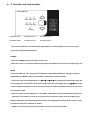
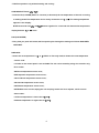
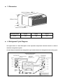
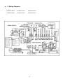
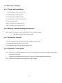
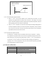
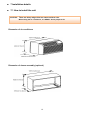
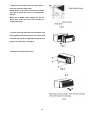
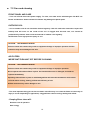
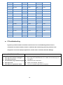
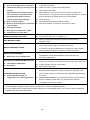
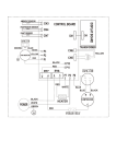
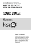
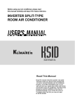
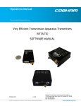
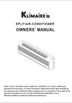
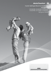
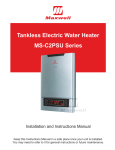
. KLIMAIRE 60Hz PTAC WINDOW Top air discharge. KTHM SERIES . . CONTENTS 1. Precaution ........................................................................................................................................... 1 1.1 Safety Precaution. ............................................................................................................................. 1 1.2 Warning .............................................................................................................................................. 1 2. Function and control panel. ............................................................................................................... 5 3. Dimension............................................................................................................................................ 7 4. Refrigerant Cycle Diagram. ................................................................................................................ 7 5. Wiring Diagram. .................................................................................................................................. 8 6 Electronic function .............................................................................................................................. 9 6.1 Terms and definitions ....................................................................................................................... 9 6.2 Electric Control working environment ............................................................................................ 9 6.3 Protection function ........................................................................................................................... 9 6.4 Operation of fan motor ..................................................................................................................... 9 6.5 Operation of compressor ............................................................................................................... 11 6.6 Sensor malfunction......................................................................................................................... 12 7 Installation details .............................................................................................................................. 13 7.1 How to install the unit ..................................................................................................................... 13 7.2 Care and cleaning ........................................................................................................................... 16 8 Operation characteristics .................................................................................................................. 18 8.1 Cooling operation. .......................................................................................................................... 18 8.2 Characteristic of temperature sensor............................................................................................ 18 9 Troubleshooting ................................................................................................................................. 19 1. Precaution 1.1 Safety Precaution. To prevent injury to the user or other people and property damage, the following instructions must be followed. Incorrect operation due to ignoring instruction will cause harm or damage. Before service unit, be sure to read this service manual at first. 1.2 Warning Installation Do not use a defective or underrated circuit breaker. Use this appliance on a dedicated circuit. There is risk of fire or electric shock. For electrical work, contact the dealer, seller, a qualified electrician, or an Authorized service center. Do not disassemble or repair the product, there is risk of fire or electric shock. Always ground the product. There is risk of fire or electric shock. Install the panel and the cover of control box securely. There is risk of fire of electric shock. Always install a dedicated circuit and breaker. Improper wiring or installation may cause fore or electric shock. Use the correctly rated breaker of fuse. There is risk of fire or electric shock. Do not modify or extend the power cable. There is risk of fire or electric shock. Do not install, remove, or reinstall the unit by yourself(customer). There is risk of fire, electric shock, explosion, or injury. Be caution when unpacking and installing the product. Sharp edges could cause injury, be especially careful of the case edges and the fins on the condenser and evaporator. For installation, always contact the dealer or an Authorized service center. There is risk of fire, electric shock, explosion, or injury. 1 Do not install the product on a defective installation stand. It may cause injury, accident, or damage to the product. Be sure the installation area does not deteriorate with age. If the base collapses, the air conditioner could fall with it, causing property damage, product failure, and personal injury. Do not let the air conditioner run for a long time when the humidity is very high and a door or a window is left open. Moisture may condense and wet or damage furniture. Take care to ensure that power cable could not be pulled out or damaged during operation. There is risk of fire or electric shock. Do not place anything on the power cable. There is risk of fire or electric shock. Do not plug or unplug the power supply plug during operation. There is risk of fire or electric shock. Do not touch (operation) the product with wet hands. There is risk of fire or electric shock. Do not place a heater or other appliance near the power cable. There is risk of fire and electric shock. Do not allow water to run into electric parts. It may cause fire, failure of the product, or electric shock. Do not store or use flammable gas or combustible near the product. There is risk of fire or failure of product. Do not use the product in a tightly closed space for a long time. Oxygen deficiency could occur. When flammable gas leaks, turn off the gas and open a window for ventilation before turn the product on. Do not use the telephone or turn switches on or off. There is risk of explosion or fire. If strange sounds, or small or smoke comes from product. Turn the breaker off or disconnect the power supply cable. There is risk of electric shock or fire. Stop operation and close the window in storm or hurricane. If possible, remove the product from the window before the hurricane arrives. 2 There is risk of property damage, failure of product, or electric shock. Do not open the inlet grill of the product during operation. (Do not touch the electrostatic filter, if the unit is so equipped.) There is risk of physical injury, electric shock, or product failure. When the product is soaked (flooded or submerged), contact an Authorized service center. There is risk of fire or electric shock. Be caution that water could not enter the product. There is risk of fire, electric shock, or product damage. Ventilate the product from time to time when operating it together with a stove, etc. There is risk of fire or electric shock. Turn the main power off when cleaning or maintaining the product. There is risk of electric shock. When the product is not be used for a long time, disconnect the power supply plug or turn off the breaker. There is risk of product damage or failure, or unintended operation. Take care to ensure that nobody could step on or fall onto the outdoor unit. This could result in personal injury and product damage. CAUTION. Always check for gas (refrigerant) leakage after installation or repair of product. Low refrigerant levels may cause failure of product. Install the drain hose to ensure that water is drained away properly. A bad connection may cause water leakage. Keep level even when installing the product. To avoid vibration of water leakage Do not install the product where the noise or hot air from the outdoor unit could damage the neighborhoods. It may cause a problem for your neighbors. Use two or more people to lift and transport the product. Avoid personal injury. Do not install the product where it will be exposed to sea wind (salt spray) directly. It may cause corrosion on the product. Corrosion, particularly on the condenser and evaporator fins, 3 could cause product malfunction or inefficient operation. Operational. Do not expose the skin directly to cool air for long periods of time. (Do not sit in the draft). This could harm to your health. Do not use the product for special purposes, such as preserving foods, works of art, etc. It is a consumer air conditioner, not a precision refrigerant system There is risk of damage or loss of property. Do not block the inlet or outlet of air flow. It may cause product failure. Use a soft cloth to clean. Do not use harsh detergents, solvents, etc. There is risk of fire, electric shock, or damage to the plastic parts of the product. Do not touch the metal parts of the product when removing the air filter. They are very sharp. There is risk of personal injury. Do not step on or put anything on the product. (outdoor units) There is risk of personal injury and failure of product. Always insert the filter securely. Clean the filter every two weeks or more often if necessary. A dirty filter reduces the efficiency of the air conditioner and could cause product malfunction or damage. Do not insert hands or other object through air inlet or outlet while the product is operated. There are sharp and moving parts that could cause personal injury. Do not drink the water drained from the product. It is not sanitary could cause serious health issues. Use a firm stool or ladder when cleaning or maintaining the product. Be careful and avoid personal injury. Replace the all batteries in the remote control with new ones of the same type. Do not mix old and new batteries or different types of batteries. There is risk of fire or explosion. Do not recharge or disassemble the batteries. Do not dispose of batteries in a fire. They may burn of explode. If the liquid from the batteries gets onto your skin or clothes, wash it well with clean water. Do not use the remote of the batteries have leaked. The chemical in batteries could cause burns or other health hazards 4 2. Function and control panel. 202021890236 KTHM009-E3C2 KTHM012-E3C2 KTHM015-E5C2 KTHM009-E3H2 KTHM012-E3H2 KTHM015-E5C2 The controls featured in this manual are representative of many available models. Your model may offer slightly different features. POWER - Press the POWER button to turn the unit on or off. When the unit is on, the power indicator light will be green.When the unit is off, the light will go out. MODE - Push this button to cycle through the modes from COOL-HEAT-FAN-COOL.The green indicator light beside the "MODE" option will illuminate, identifying the mode selected. - COOL:The range of set temperature is 17℃/62℉~30℃/86℉.Cooling begins automatically when the room temperature is above the set point,and stops when the room temperature is 2℃(4℉) below the set point. But the compressor will run 5 minutes at least in COOL mode before stoping. The fan runs in continuous mode. - HEAT:The range of set temperature is 17OC/62OF ~29OC/84OF.For heat pump models,the unit can alternate to run between in reverse cycle heat mode and electric heater mode according to the difference between the setting temperature and the room temperature.The fan motor cycles on and off with the compressor and electric heater. NOTE: The reverse cycle and electric heater can not be run at the same time. 5 - FAN:Fan operation only without heating and cooling. UP/DOWN BUTTONS ( / ) - Push the UP (or DOWN) button to increase (or decrease) the set temperature of the unit in cooling or heating mode.The temperature can be set by increments of 1℃ (1℉).The setting temperature appears in the display. NOTE:Press and hold and buttons together for 3 seconds will alternate the temperature display between ℃ & ℉ scale. FAN (FAN SPEED) - Every time you push this button,the fan speed cycles through the settings as follows:HIGH-MEDLOW-HIGH. DISPLAYS: - Shows the set temperature in ℃ or ℉. While on Fan only mode,it shows the room temperature. Control code: LC-Pads on the control panel is not available.The unit can be setted by using wire cotroller only. Error codes: AS-Room temperature sensor error; ES-Evaporator temperature sensor error; CS-Condenser temperature sensor error; OS-Outside temperature sensor error; HS-Exhaust temperature sensor error; NOTE:When error occurs,unplug the unit and plug it back in.If error repeats, call for service. Other codes: LO-Room temperature is lower than 0℃/32℉; HI-Room temperature is higher than 37℃/99℉. 6 3. Dimension. Dimension Mode W(mm) H(mm) D(mm) PTAC 1067 408 606 4. Refrigerant Cycle Diagram. The figure below is a brief description of the important components and their function in what is called the refrigeration system. This will help to understand the refrigeration cycle and the flow of the refrigerant in the cooling cycle. 7 5. Wiring Diagram. KTHM009-E3C2 KTHM012-E3C2 KTHM015-E5C2 KTHM009-E3H2 KTHM012-E3H2 KTHM015-E5C2 8 6 Electronic function 6.1 Terms and definitions T1: Temperature of indoor ambient (TA) T2: Temperature of evaporator (TC). T3: Temperature of condenser (TE) T4: Temperature of outdoor ambient (T0) TS: The set temperature. DAHT: Temperature of discharge (T5) DAHT: Temperature of discharge (T6) 6.2 Electric Control working environment Input voltage: 187~264V for 50Hz models and 97~127V for 60Hz models; 208~230V or 238~291V for 60Hz models 6.3 Protection function 6.3.1 The compressor functions protection with a delay of three minutes. 6.3.2 Sensor protection at open or short circuit. 6.3.3 Evaporator anti-icing protection at cooling mode. 6.4 Operation of fan motor 6.4.1. Fan motor is on when compressor is on, Fan motor is off when compressor is off. (except theT2 high Temp. protection). If there’s only one speed of the fan motor, use the high speed instead of the low speed. 6.4.2. The fan motor operates at the cooling only mode as below: 9 T4 Operate on high speed T01 T02 Operate on low speed When T4﹥T01 and lasts for 1 minute, the fan motor will operates at high speed. When T4﹤T02 and lasts for 1 minute, the fan motor will operates at low speed. When T02≤T4≤T01: A) If fan motor is off originally, it will operate at high speed. B) If fan motor is on originally, it will keep on working at the original speed. 6.4.3. The fan motor operates at the heat pump and cooling mode as below: T4 Operate on low speed T03 T04 Operate on high speed When T4≥T03 and lasts for 1 minute, the fan motor will operates at low speed. When T4≤T04 and lasts for 1 minute, the fan motor will operates at high speed. When T04﹤T4﹤T03: A) If fan motor is off originally, it will operate at high speed. B) If fan motor is on originally, it will keep on working at the original speed. 6.4.4. The high temperature protection of evaporator at the heat pump and cooling mode as below: 10 TE7 TE8 TE15 Compressor Fan motor Fan motor (low speed) Compressor on Fan motor on (High/low speed is determined by T4) Compressor Fan motor Compressor on Fan motor on (High/low speed is determined by T4) TE9 If T2﹥TE7, this unit turns into the protection of compressor off , and quits this protection when T2≤TE9. If T2﹥TE8,it turns into the protection of fan motor off , and quits this protection when T2≤TE9. If T2﹥TE15, fan motor operates at low speed by force, then quits the operation and determines the high or low speed by T4. 6.4.5. At the fan only mode, the fan always keeps on working, and the compressor/fan motor/heater stop working. 6.5 Operation of compressor 6.5.1. The compressor operates at cooling mode as below: Operation conditon (T1-Ts)℉ Compressor on +0 -4 Compressor off T1≥Ts compressor on T1≤Ts-4℉ compressor off 6.5.2. The compressor operates at heating mode: (There are two ways of heating mode: Heat pump and cooling/Electric heater and cooling) The electrical heater or compressor will be activated by sensing the difference between setting temperature and the actual ambient room temperature. 11 Operation conditon for heater or compressor Heater(compressor) off (T1-Ts)℉ 2 -2 Heater(compressor) on 6.5.2.1 The Electric heater operates as below: a. When T1﹤Ts-2℉, the fan motor operates, and 3 seconds later, the heater is on and operates at low speed within 30 seconds. After 30 seconds, it will change to the setting speed. If the DAHT temperature checked is higher than the protection temperature, when the heater operating, the fan motor will be off automatically. b. When T1≥Ts+2℉, the heater is off, and the fan motor keeps on working at setting speed. If the DAHT temperature checked is low than the protection temperature, and the operation time of fan motor is more than 15 seconds, then the fan motor will be off. If the T2 protection gets started, the fan motor also does not work. 6.5.2.2 The Heat pump operates as below: The Heat pump′s operation mode is in accordance with the way of compressor′s working. The compressor is on (electric heater is off), the fan motor operates according to the anti-cold wind of heat pump. The four-way valve always keeps on. When T1﹤Ts-2℉, the compressor is on, and when T1≥Ts+2℉,it will be off. The fan motor works according to the operation of compressor. If T2﹥TE7, the compressor is off by force. When the DAHT protection gets started, it is not allowed that the compressor operates. 6.6 Sensor malfunction LED display Stand for AS Room temperature sensor error(T1) Es Room temperature sensor error(T2) CS Condenser temperature sensor error(T3) OS Outside temperature sensor error(T4) HS Exhaust temperature sensor error(T5,T6) 12 7 Installation details 7.1 How to install the unit CAUTION: There are sharp edges that can cause serious cuts. When lifting the air conditioner, it is HEAVY. Use 2 people to lift. Dimension of air conditioner Dimension of sleeve assembly (optional) 13 - For existing sleeve, you should measure the wall sleeve dimensions. - Install the new air conditioner according to these installation instructions to achieve the best performance. All wall sleeves used to mount the new air conditioner must be in good structural condition and have a rear grille that securely attaches to the sleeve or the flange of the sleeve to secure the new air conditioner. - To avoid vibration and noise, make sure the unit is installed securely and firmly. - When installing the sleeve, make certain there is nothing within 20 of the back that would interfere with heat radiation and exhaust air flow. (See Fig.2) PREPARATION OF SLEEVE ASSEMBLY (optional) - Refer to the installation instruction of sleeve assembly for details. UNIT INSTALLATION - Carefully remove shipping tape from the front panel. (See Fig.3) - Remove the front panel. (See Fig.4) - Remove the shipping screw from the vent door.(See Fig.5) 14 - Rotate the vent control lever to either open or close the vent door.(See Fig.6) NOTE: When vent control lever set at CLOSE, only the air inside the room is circulated and filtered. When set at OPEN, some outdoor air will be drawn into room. This will reduce heating or cooling efficiency. - Lift unit level and slide unit into wall sleeve until firmly against front of wall sleeve and secure with 4 screws and washers (supplied) through the unit flange holes. (See Fig.7 and Fig.8) - Reinstall front panel.(See Fig.9) 15 7.2 Care and cleaning FRONT PANEL AND CARE - Turn unit off and disconnect power supply. To clean, use water and a mild detergent. DO NOT use bleach and abrasive. Some commercial cleaners may damage the plastic parts. OUTDOOR COIL - Coil on outdoor side of unit should be checked regularly. Unit will need to be removed to inspect dirt build-up that will occur on the inside of the coil. If clogged with dirt and soot, coil should be professionally cleaned. Clean inside and outside of outdoor coils regularly. NOTE: Never use a high-pressure spray on coil. CAUTION: UNIT DAMAGE HAZARD Failure to follow this caution may result in equipment damage or improper operation. Airflow restriction may cause damage to the unit. AIR FILTERS IMPORTANT:TURN UNIT OFF BEFORE CLEANING. CAUTION: UNIT DAMAGE HAZARD Failure to follow this caution may result in equipment damage or improper operation. Do not operate unit without filters in place. If a filter becomes torn or damaged, it should be replaced immediately. Operating without filters in place or with damaged filter will allow dirt and dust to reach indoor coil and reduce cooling, heating, airflow and efficiency of unit. Airflow restriction may cause damage to unit. - The most important thing you can do to maintain unit efficiency is to clean the filters at least every 30 days (or sooner depending on application). Clogged filters reduce cooling, heating and airflow. - Keeping filters clean will: Decrease cost of operation. Save energy. 16 Prevent clogged indoor coil. Reduce risk of premature component failure. - To Clean Air Filters: Vacuum off heavy soil. Run water through filter. Dry thoroughly before replacing. - Removing Air Filter (See.Fig.10) - Replacing Air Filter (See.Fig.11) VENT DOOR FILTER IMPORTANT:TURN UNIT OFF BEFORE CLEANING. - Make sure to remove the shipping screw from the vent door.(See.Fig.5) - Rotate the vent control lever to open the vent door. (See. Fig.6) - Remove four screws from the vent door filter. (See.Fig.12) - First pull out the vent door steel wire from the hole of the vent door, then take off the vent door and filter. (See.Fig.12) - Clean the filter. Dry thoroughly before replacing. - Replace the vent door and filter, reinstall the four screws. - Reinsert the vent door steel wire into the hole of the vent door. 17 8 Operation characteristics 8.1 Cooling operation. Outdoor air temp.℃ DB Indoor air temp. ℃ DB 8.2 Characteristic of temperature sensor. Temp.℃ Resistance KΩ Temp.℃ Resistance KΩ Temp.℃ Resistance KΩ -10 62.2756 17 14.6181 44 4.3874 -9 58.7079 18 13.918 45 4.2126 -8 56.3694 19 13.2631 46 4.0459 -7 52.2438 20 12.6431 47 3.8867 -6 49.3161 21 12.0561 48 3.7348 -5 46.5725 22 11.5 49 3.5896 -4 44 23 10.9731 50 3.451 -3 41.5878 24 10.4736 51 3.3185 -2 39.8239 25 10 52 3.1918 -1 37.1988 26 9.5507 53 3.0707 0 35.2024 27 9.1245 54 2.959 1 33.3269 28 8.7198 55 2.8442 18 2 31.5635 29 8.3357 56 2.7382 3 29.9058 30 7.9708 57 2.6368 4 28.3459 31 7.6241 58 2.5397 5 26.8778 32 7.2946 59 2.4468 6 25.4954 33 6.9814 60 2.3577 7 24.1932 34 6.6835 61 2.2725 8 22.5662 35 6.4002 62 2.1907 9 21.8094 36 6.1306 63 2.1124 10 20.7184 37 5.8736 64 2.0373 11 19.6891 38 5.6296 65 1.9653 12 18.7177 39 5.3969 66 1.8963 13 17.8005 40 5.1752 67 1.830 14 16.9341 41 4.9639 68 1.7665 15 16.1156 42 4.7625 69 1.7055 16 15.3418 43 4.5705 70 1.6469 9 Troubleshooting In general, possible trouble is classified in three kinds. One is called Starting Failure which is caused from an electrical defect, another is ineffective Air Conditioning caused by a defect in the refrigeration circuit and improper application, and the other is called the Structure Damage. POSSIBLE CAUSES UNIT DOES NOT START Solution Check that plug is plugged securely in wall receptacle. Unit may have become unplugged Note: Plug has a test/reset button on it. Make sure that the plug has Fuse may have blown not tripped. Circuit breaker may have been tripped Replace the fuse. See Note 1. Unit may be off Reset circuit breaker. See Note 1. Unit may be in a protection mode. Turn unit on (bottom right button on keypad). 19 UNIT NOT COOLING/HEATING ROOM Make sure that curtains, blinds or furniture are not restricting Unit air discharge section is blocked Temperature setting is not high or low Reset to a lower or higher temperature setting. enough. Remove and clean filters. Note: Set point limits may not allow Allow sufficient amount of time for unit to heat or cool the room. or blocking unit airflow. the unit to heat or cool the room to Start heating or cooling early before outdoor temperature, cooking the temperature desired. Check heat or gatherings of people make room uncomfortable. section on dip switch settings. Close vent door. Unit air filters are dirty. Check dipswitch settings for desired comfort. Room is excessively hot or cold when Wait approximately 3 minutes for compressor to start. DISPLAY HAS STRANGE The unit may be in a protection mode. NUMBERS/CHARACTERS ON IT The unit may be set for ℃ (instead of ℉). Clicking, gurgling and whooshing noises are normal during unit is started. Vent door left open. Unit may be in a protection mode. Compressor is in time delay. UNIT MAKING NOISES operation of unit. If a drain kit has not been installed, condensation runoff during very hot and humid weather is normal. See Note 2. WATER DRIPPING OUTSIDE If a drain kit has been installed and is connected to a drain system, check gaskets and fittings around drain for leaks and plugs. WATER DRIPPING INSIDE condensation. Check that installation is level and make any Wall sleeve is not installed level ICE OR FROST FORMS ON INDOOR COIL Low outdoor temperature Dirty filters Wall sleeve must be installed level for proper drainage of necessary adjustments. When outdoor temperature is approximately 55 ℉ or below, frost may form on the indoor coil when unit is in Cooling mode. Switch unit to FAN operation until ice or frost melts. Remove and clean filters. Random Compressor restart-Whenever the unit is plugged in, or power has been restarted, a random compressor restart will occur. COMPRESSOR PROTECTION After a power outage, the compressor will restart after approximately 3 minutes. Power may have cycled, so compressor is in a restart protection. Compressor Protection-To prevent short cycling of the compressor, there is a random startup delay of 3 minutes and a minimum compressor run time of 3 minutes. NOTES: 1. If circuit breaker is tripped or fuse is blown more than once, contact a qualified electrician. 2. If unit is installed where condensation drainage could drip in an undesirable location, an accessory drain kit should be installed and connected to drain system. 20 The Klimaire logo is a registered Trademark of Klimaire Products inc. Copyright 2010 Klimaire Products Inc. 2190 NW 89 Place, Doral, FL 33172 - USA 21