1
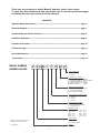
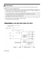
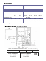
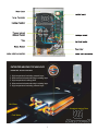
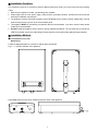
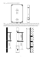
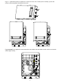
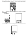
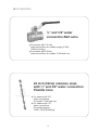
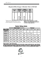
Tankless Electric Water Heater
MS-C2PSU Series
Installation and Instructions Manual
Keep this Instructions Manual in a safe place once your unit is installed.
You may need to refer to it for general instructions or future maintenance.
Thank you for purchasing a quality Maxwell tank-less electric water heater.
To enjoy your new shower at its best, please take time to read this manual thoroughly
and having done so keep it handy for future reference.
CONTENTS
Important Safety Instructions -------------------------------------------------------------------------------- page 2
Electrical Diagram------------------------------------------------------------------------------------------------ page 3
Technical Data and Product Structure----------------------------------------------------------------------page 4
Installation Guideline---------------------------------------------------------------------------------------------page 6
Operation Instructions ------------------------------------------------------------------------------------------page 10
Trouble-shooting---------------------------------------------------------------------------------------------------page 11
Normal Maintenance----------------------------------------------------------------------------------------------page 11
Accessories--------------------------------------------------------------------------------------------------------page 12
MODEL NUMBER
NOMENCLATURE
M
S 120 C
2
P
W
U
Test Calification
U : UL/ETL
C : CSA
Casing Type & Color
B: Injection Molding – Black
D: Injection Molding – Silver w/Dots
S: Injection Molding – Silver
W:Injection Molding – White
M:Metal Casing
– Silver
Minor Design Change
P : Plate Heater Exchanger
T : Tubular Stainless
Steel Heat Exchanger
Power Supply Code (V/ph)
1 – 120 / 1
2 – 240 / 1
5 – 240 / 3
Temperature Control
C : Automatic Constant
P : Power Level
Capacity (kW)
035
045
055
075
080
–
–
–
–
–
3.5
4.5
5.5
7.5
8.0
100
120
150
180
210
Heater Type
S : Tankless
H : Holding Tank
This Klimaire nomenclature supercedes
all previously issued (06/07/2011)
Brand:
M: Maxwell
PUB: M9SH1102
1
–
–
–
–
–
10.0
12.0
15.0
18.0
21.0
Installation of this product is restricted to indoor locations by licensed plumbing or electrical
contractors only. By installing this product you acknowledge the terms of manufacturer's warranty and
your authorized dealers return policy. Water heaters that have been installed cannot be returned.
If you plan to install your water heater on a second floor/above ground or in a heated attic space you must
follow all code requirements for installation in your area. It is highly recommended to install a drip pan
connected to a safe drain as per code requirements, below the water heater to avoid property damage in
case of eventual leaks, and / or install an active water leak detector and shut off valve to turn off your
water supply in the event that a leak is ever detected.
■ Important Safety Instructions
1. The installation must be in compliance with the National Electrical Code, your local electrical and
plumbing codes.
2. This appliance must be GROUNDED.
3. All wiring and installation jobs must be supervised by a qualified electrician.
4. CAUTION: This product has more than one power-supply connection point. Disconnect all power supplies
before servicing.
5. This appliance is not intended for use by persons (including children) with reduced physical, sensory or mental
capabilities, or lack of experience and knowledge, unless they have been given supervision or instruction concerning
use of the appliance by a person responsible for their safety. Children should be supervised to ensure that they do
not play with the appliance.
6. This appliance MUST be permanently connected to a fixed circuit breaker and it must be installed vertically. DO
NOT install this appliance near flammable substances or near a strong magnetic field place.
7. It is forbidden to switch on this appliance if you think it may be frozen, as this could result in serious damage to
the unit. Wait until you are sure that it has completely thawed out before switching it on.
8. Please check the hot water temperature with your hand to make sure it is at a comfortable temperature before
taking a shower to avoid getting scalded.
9. Before connecting pipes to the water heater hoses, it is extremely important to FLUSH the pipes to wash away all
plumbing paste or residue in the pipes.
10. The heating chamber is treated with composite nano-insulation material; it is natural there might be a bit of smell
or green blue smoke when the unit is used for the first time.
11. If there is damage to the wire, you must contact a qua lified electrician to replace it with an approved wire.
12. CAUTION: FOR HOUSEHOLD AND INDOOR USE ONLY
13. Combustible materials should be kept at least 2 ft away from your water heater and output water pipe.
14. AFTER TIGHTENING BOTH FITTINGS AT THE WATER HEATER OPEN SEVERAL HOT WATER FAUCETS
AND ALLOW WATER TO RUN THROUGH THE WATER HEATER FOR AT LEAST 3 MINUTES. THIS
PROCESS PURGES ALL AIR FROM THE WATER LINES AND HEATER.
HIS PROCESS MUST BE PERFORMED PRIOR TO TURNING ON THE POWER OF THE WATER HEATER.
FAILURE TO FOLLOW THIS STEP CAN CAUSE PERMANENT DAMAGE TO THE HEATING ELEMENT.
2
■ Product Features
The Maxwell tank-less electric water heaters are made with multi-safety devices patented technology
Additionally, the unit has the following features.
1. Tank-less, instantaneous heating on demand. No pr e-heating. No stand-by heating loss energy-saving.
2. Micro-computer control, adopting patented heating technology. Water is completely separated from
electricity by multi-layers of composite nano insulation material.
3. Over-heating thermal cut-off. When the outlet water temperature reaches over 140℉/60ºC, the electricity
will be cut off automatically to avoid getting scalded and the screen beeps and displays E1.
4. Creepage protection. If the unit detects electricity leakage, the electricity will be cut off within mil seconds
by the creepage protector and the screen displays E2.
5. Malfunction sensor- when the temperature sensor malfunctions, the heater stops working and displays E3
6. Conversion between Fahrenheit degrees and Celsius degrees.
7. This product does not require venting.
AC 240V/60Hz
3
■ Technical Data
Model
MS80C2P_U
MS100C2P_U
1
Phase
Voltage/Freq
V
Wattage
kW
Max. amp.load
A
Min. required circuit breaker*
A
Min. wire size AWG cooper
MS120C2P_U
1
240 V/60Hz
240 V/60Hz
MS150C2P_U
MS180C2P_U
MS210C2P_U
1
1
1
1
240 V/60Hz
240 V/60Hz
240 V/60Hz
240 V/60Hz
12kw
15kw
18kw
21kw
8kw
10kw
34
42
50
63
75
88
45
60
60
2 X 40
2 X 50
2 X 60
8
6
6
2X8
2X8
2X8
0.53 / 2
0.53 / 2
0.53 / 2
0.85 / 3.2
Min. water flow to activate
GPM / L/min.
0.85 / 3.2
Max.150/10
lb
7.7
7.7
7.7
12.1
12.1
12.1
kg
3.5
3.5
3.5
5.5
5.5
5.5
mm 385x260x93
385x260x93
385x260x93
385x260x93
385x260x93
385x260x93
in 15.2"x10.2"x3.7" 15.2"x10.2"x3.7" 15.2"x10.2"x3.7" 15.2"x10.2"x3.7" 15.2"x10.2"x3.7" 15.2"x10.2"x3.7"
NPT
1/2”
1/2”
1/2”
3/4”
3/4”
3/4”
Working pressure PSI/bar
Weight
Product Dimensions
Water connections
Note: *suitable recognized strain relief means shall be provided when the product installed.
(MS150, MS180, MS210)
16.14"
11.02"
WIRE CONNECTIONS TO BREAKERS (MS150, MS180, MS210)
L1
0.85 / 3.2
L2
DOUBLE POLE BREAKER
40 Amp MS150
50 Amp MS180
60 Amp MS210
L1
L2
DOUBLE POLE BREAKER
40 Amp MS150
50 Amp MS180
60 Amp MS210
4
E/G
EARTH/
GROUND
PATENTED HEATING TECHNOLOGY
PATENT NO.: ZL2008 2 0081568.0
1. High temperature insulating ceramic layer.
2. Macromolecule heatconducting insulating layer.
3. High temperature heating plate.
4. Macromolecule heatconducting insulating layer.
5. High temperature insulating ceramic layer.
Hot Water
Sheathed Heating Plate
Cold Water
5
■ Installation Guideline
The installation must be in compliance with the National Electrical Code, your local electrical and plumbing
codes.
1. Make sure the appliance is intact, and the fittings are complete.
2. Please make sure the main power supply, water pressure, grounding condition, ammeter and wires meet the
standard of installation requirements.
3. The appliance must be connected to properly ground dedicated branch circuits of proper voltage rating. Ground
must be brought to the “ground” at the circuit breaker panel.
4. This appliance MUST be permanently connected to the fixed circuit breaker. If you don’t use the heater, please
switch off the circuit breaker.
5. DO NOT install this appliance near to tinder or strong magnetic field places. The unit must only be mounted in
VERTICAL position near by the water fittings. Please electrify try the machine after getting through waterway.
■ Installation Method
●Fixed installation on the wall
MS-PSU Series
Locate an appropriate place on a section of wall as above mentioned.
Fig 1
Fig 2
Front and back of the appliance
Remove screw which fixed the bracket on back of the appliance.
6
Fig 3
Remove the bracket from the appliance
3.94"
3.94"
3.94"
3.94"
Fig 4
Hold the back bracket hanger in position against the wall and mark the three mounting holes. Drill
three holes of 6.00mm diameter, the distance between every two holes is 100mm. (Put plastic anchor in the hole, fix
the bracket on the wall. and secure the hanger using the screws supplied or an appropriate alternative method)
.
7
Fig 5
Uninstall screws on appliance to remove the front cover. Please pull out carefully by hand the
screen row line plug before removing the front cover.
Fig 6
Fix the appliance to the bracket which was nailed to the wall, Make sure the unit fits onto the back
metal hanger correctly
8
Fig 7
Connect the cable to the terminal
blocks, please notice the guidance logo below the terminal
blocks. MS080C2PSU, MS100C2PSU, MS120C2PSU will be connected to one circuit breaker, MS150C2PSU,
MS180C2PSU, MS210C2PSU will be connected to two circuit breakers.
Fig 8
Fix the front cover on appliance, before that, please plug in the screen row line plug. Then nail the
screws to fix the cover.
Fig 9
Connect the water pipe to the water inlet and water outlet connections, please remember to
install the rubber seal ring.
15.15"
10.24"
9
● Water connections
1. All water pipe must comply with national and applicable state and local water pipe codes.
2. A pressure relief valve must be installed if the cold water supply pressure exceeds 150PSI (1Mpa)
3. The unit should be connected directly to the main water supply. Flush pipe with water to remove any debris or
loose particles
4. It is required to use 1/2”NPT water connections to fit the models MS080C2PSU, MS100C2PSU, MS120C2PSU;
use 3/4”NPT water connections to fit the models of MS150C2PSU, MS180C2PSU, MS210C2PSU, MS150C2PMU,
MS180C2PMU, MS210C2PMU.
5. Please remember to install the rubber seal o’ rings at the connections. When all water connections are completed,
check for leaks and take corrective action before proceeding.
● Electrical connection
1. All electrical work must comply with national and applicable state and local electrical codes.
2. All units must be connected to a properly grounded dedicated branch circuit of proper voltage rating.
3, MS080C2PSU, MS100C2PSU, MS120C2PSU can be connected to a single circuit, use a supply cable protected
by a double pole breaker. MS150C2PSU, MS180C2PSU, MS210C2PSU require two independent circuits. Use two
supply cables protected by two separate double pole breakers.
4. While connecting the cables to terminal the blocks, please make sure the metal wire ends and the terminal blocks
to touch completely. Then tighten the screws up to make sure the current can go through.
5. Before beginning any work on the electric installation, be sure that main panel breaker switch is OFF to avoid any
danger of electric shock, all mounting and plumbing must be completed before proceeding with electrical hook-up.
■ Operation Instructions
MS-PSU Series
1. Turn on the circuit breaker to bring electrical power to the unit.
2. Open water faucet for a few minutes until water flow is continuous and all air is purged from water pipes. The unit
must be operated after the breakers are turned on.
3. After the unit is powered, a beep sound can be heard and a LED lights for 2 seconds, no other display, the
appliance keeps standby.
4. Press “
” to turn ON/OFF the appliance. When the unit is ON, LED displays actual water temperature of the
outlet. When the appliance stops working, the screen switches to the screen saver after 5 seconds. The display
screen light will be off. If the screen is touched, it will be lighted again.
5. Press
z
z
z
and
to adjust the outlet temperature. Temperature setting range is 30—53 ºC / 82-127 ℉.
If the unit has been paused, you may initially get a short burst of very hot water while you turn it on again. Please
run the water through for a few seconds to let the temperature settle down. Please check water temperature with
your hand before taking a shower.
If the unit will not be used in winter, drain out water completely so that the heater will not be frozen.
Please periodically clean inlet strainer and the shower to keep a free water flow.
6. Press
then press
to convert the temperature display between Fahrenheit degree and Celsius degree.
7. There is an automatic memory function to avoid repetitive operation, while you turn on the appliance, the default
set temperature will be the same as set last time.
10
■ Trouble-shooting
Problems
1. Inlet and outlet fittings leaking
2. LED no signal
3. Functional keys not working
Possible Causes
Corrective Actions
A. Fittings not tight
A. Tighten fittings.
B. Rubber washer worn-out
B. Change rubber washer.
A. Power not connected.
A. Connect power to the unit.
B. LCD damaged.
B. Change LCD.
A. No water out from shower.
A. Open valve to get water.
B. Water pressure too low.
B. Open valve to get pressure.
C. Key or PCB damaged.
C. Change key or PCB.
A. Temperature set too high
A. Set a lower temperature.
B. Water flow too small.
B. Increase valve opening.
5. Water too cold
A. Low temperature set.
A. Set a higher temperature.
B. Too much water flow.
B. Reduce water flow.
6. Outlet gets less and less water.
Inlet strainer or shower clogged.
Clean strainer and shower.
7. LED displays E1
Outlet temp. is over 60℃/140℉
A, Reduce the temperature
4. Water too hot
B, Increase the water flow
8. LED displays E2
There is electricity leakage
Please contact your local dealer
9. LED displays E3
Temperature sensor failure
Please contact your local dealer
10. Display overload
Inlet water flow is too big.
Reduce the inlet water flow
7, 8 and 9 should only be performed by a qualified electrician. The person who initially installed the unit is
the best one to contact for help.
■ Normal Maintenance
Note: Do not attempt to repair this water heater yourself. Call a service person for assistance. Always turn
off the power supply before servicing your unit.
It is not required any regular maintenance. However, to ensure consistent water flow, the following
maintenance is recommended.
1. Periodically remove scale and dirt that may build up at the aerator of the faucet or in the shower head.
2. There is a built in filter screen at the inlet connection which should be cleaned from time to time. Please turn off the
water flow before doing this.
11
■ ACCESSORIES
½” and 3/4" water
connection Ball valve
For heaters with 1/2” inlet
water connections for models ranging 3.3kW-,
12kW (including)
For heaters with 3/4”inlet
water connections for models 15 kW and over
24 inch (60cm) stainless steel,
with ½” and 3/4" water connection
Flexible hose
For heaters with 3/4”
water connections
for models 15 kW and over
For heaters with 1/2”
water connections
for models ranging
3.3kW-,12kW (including)
12
■ TABLES
Required Wire Gauge & Breaker Size @ 230 Volt
**
* Maximum power (Amp.) based on 230 V. For 240 V
application see specification table on page 4. ……
** All above breakers are of the double pole type.
Warning: It is recommended to use restrictors for showers and faucets to prevent excessive water consumption.
13
Klimaire Products Inc.
2190 NW 89 Place Doral, FL 33172 - USA
Phone: 305 5938358 Fax: 305 5938 212