1
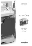
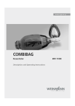
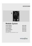
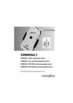
ACCUVAC Basic
Aspirator
WM 10700
Service and Repair Instructions
Contents
Introduction . . . . . . . . . . . . . . . . . . . . . . . . . 3
1. Overview . . . . . . . . . . . . . . . . . . . . . . . . . . . 4
2. Description . . . . . . . . . . . . . . . . . . . . . . . . . . 5
2.1 Purpose . . . . . . . . . . . . . . . . . . . . . . 5
2.2 Function . . . . . . . . . . . . . . . . . . . . . . 5
3. Operation . . . . . . . . . . . . . . . . . . . . . . . . . . 7
4. Operating and Display Elements . . . . . . . . . . 7
5. Maintenance . . . . . . . . . . . . . . . . . . . . . . . . . 7
5.1 Disposal . . . . . . . . . . . . . . . . . . . . . 7
6. Functional checks . . . . . . . . . . . . . . . . . . . . . 8
6.1 Intervals . . . . . . . . . . . . . . . . . . . . . . 8
6.2 Performing the functional check. . . . . . . 8
7. Troubleshooting . . . . . . . . . . . . . . . . . . . . . 10
8. Repairs: Information and Instructions . . . . . . 12
8.1 General . . . . . . . . . . . . . . . . . . . . . 12
8.2 Opening the device . . . . . . . . . . . . . 12
8.3 Closing the device . . . . . . . . . . . . . . 13
8.4 Replacing release catch . . . . . . . . . . 13
8.5 Replacing membrane keyboard . . . . . 14
8.6 Changing power pack . . . . . . . . . . . 16
8.7 Changing fuse F1 or F2 . . . . . . . . . . 17
8.8 Check connector between circuit board
and power pack . . . . . . . . . . . . . . . 18
8.9 Fitting new circuit board WM 10780 . 18
8.10 Fitting new pressure gage . . . . . . . . . 20
8.11 Fitting new vacuum regulator . . . . . . . 20
8.12 Fitting new pump . . . . . . . . . . . . . . . 21
8.13 Changing fuse in vehicle plug . . . . . . 22
8.14 Changing the muffler . . . . . . . . . . . . 22
8.15 Electrical circuit diagram . . . . . . . . . . 23
9. Spare Parts . . . . . . . . . . . . . . . . . . . . . . . . . 24
9.1 Spare parts list . . . . . . . . . . . . . . . . 24
10. Tools and Test Equipment . . . . . . . . . . . . . . 26
11. Technical Changes . . . . . . . . . . . . . . . . . . . 26
12. Technical Data . . . . . . . . . . . . . . . . . . . . . . 27
12.1 Safe distances. . . . . . . . . . . . . . . . . 28
13. Repair and Test Report . . . . . . . . . . . . . . . . 29
© Copyright WEINMANN GmbH & Co. KG.
The content and presentation are copyright protected and may only be used by authorised WEINMANN Service Partners in
the course of their service operations. The content must not be reproduced or passed on to third parties. The complete documents
must be returned on termination of the cooperation with WEINMANN.
2
Introduction
For decades WEINMANN has been developing,
manufacturing and marketing appliances for emergency medical treatment, oxygen therapy and
inhalation therapy.
In 1986 WEINMANN launched the first
ACCUVAC aspirator on the market.
The improved ACCUVAC Basic aspirator provides users with an appliance that is an indispensable aid in many emergency health care situations. The ACCUVAC Basic is primarily intended
for oral or transtracheal aspiration of secretion.
Aspiration is indicated in particular for tracheotomy patients undergoing respiration.
The indications include:
• Neuromuscular disorders, e.g. paraplegia,
amyotrophic lateral sclerosis (ALS)
• Late symptoms of polio
• Muscular dystrophies
• Cystic fibrosis
• Kyphoskoliosis and posttubercular syndrome
• Chronic obstructive lung diseases, e.g. severe
chronic bronchitis
• Pulmonary fibrosis, e.g. silicosis
• Other forms of alveolar hypoventilation
Using the ACCUVAC Basic aspirator gives the
user more time to look after the patient and perform
other measures.
The purpose of these Service and Repair Instructions is to make sure you as an expert specialist are
familiar with the ACCUVAC Basic aspirator: its
functionality and technology and how to repair it.
Combined with training you have already received from WEINMANN, this makes you a member of the “authorized expert personnel” category,
which means you can give your customers proper
instruction, remedy faults independently, perform
the final checks specified in the Operating Instructions, and carry out any repairs in accordance with
these Service and Repair Instructions.
In the event of a warranty claim the ACCUVAC Basic
aspirator is to be sent to WEINMANN.
So that we can process warranty claims or requests for generous treatment of complaints,
please send the purchase receipt (invoice) with the
appliance.
Repairs may only be carried out by WEINMANN
or by expert personnel.
You are responsible for any repairs you make and for
the relevant warranty!
Only original WEINMANN spare parts must be used
for repairs.
Please remember:
Your customer trusts you and relies on your quality,
just as you rely on WEINMANN.
Note:
For the following information, please consult the
ACCUVAC Basic Operating Instructions:
• Safety information
• Fitting accessories
• Operation
• Hygienic preparation
• Warranty
Introduction
3
0
-0,2
8 Motor unit
11 Adapter/charger
plug
12 Power socket
(hidden)
13 Muffler
(hidden)
14 Suction port
10 Loops for
accessory bag
ACCUVAC Basic from rear without collection canister
1 Pressure gauge
9 Tube holder plate
4 On/Off
switch
3 Voltage indicator
2 Vacuum control
-0,6 -0,4
-1,0
-0,8
6 Release catch
7 Disposable
canister
5 Membrane keyboard
ACCUVAC Basic from front with disposable collection canister
17 Power pack
38 Holder set WM 15271
37 Collection canister
36 Aspiration tube
35 Fingertip
34 Sealing ring
26 Re-usable collection canister WM 15269
27 Vent tab
28 Filter cover
29 Bacteria filter
30 Locking tab
31 Bracing
32 Secretion cover
33 Ball (overfill guard)
Accessories
18 Plug X100
15 Fuse F100 16 Fuse F101 (hidden)
ACCUVAC Basic interior
Connection cable
WM 10650
Accessory bag
WM 10655
Wall bracket
WM 15208
Mains / charger unit
FW7405M/14,
complete WM 2610
11 Adapter/charger plug
25 Holder
24 Collection canister
23 T-piece
22 Vacuum
tube
21 Disposable bag
20 Intermediate tube
19 Aspiration tube with
Fingertip
Disposable collection canister
1. Overview
2. Description
2.1 Purpose
ACCUVAC Basic is a mobile and portable electrically powered aspirator (suction pump).
It is used for:
•
•
aspirating accumulations of blood, secretions
and food from the oral cavity, the nose and
throat region and the bronchial system;
deflating vacuum mattresses and inflatable
splints.
ACCUVAC Basic:
• can when used by a skilled operator eliminate
obstruction of the respiratory tract and hence
the risk of respiratory failure;
•
•
•
•
cuts energy consumption by reducing power
output on reaching the necessary vacuum;
can optionally be powered by a rechargeable
internal power pack;
or by an external DC source supplying 12.0 13.8 V;
is also suitable for use in wards.
ACCUVAC Basic must not be used:
• in medical rooms where potential equalization
is necessary (e.g. heart surgery);
• in explosion-risk areas.
2.2 Function
An electrically operated diaphragm pump generates
the vacuum necessary for aspiration.
Use the vacuum control 2 to set the desired vacuum,
which is continuously variable between –0.05 bar
and –0.8 bar. You can read off the set value on the
pressure gage 1.
-0,6 -0,4
-0,2
-0,8
-1,0
0
The aspirated material passes via the aspiration tube
36 into the disposable collection canister 7.
Disposable collection canister
The disposable collection canister 7 consists of the
collection canister 24 itself, the disposable collection
bag 21 with intermediate tube 20, the aspiration tube
with fingertip 19, the T-piece 23 and the vacuum tube
22.
The disposable collection canister 7 is inserted in the
holder 25 screwed on the side of the motor unit 8.
The vacuum tube 22 of the disposable canister 24 is
pushed onto the suction port 14 of the motor unit 8.
Description
5
The aspirated material passes through the aspiration tube 19 into the disposable collection bag 21.
The disposable collection bag is intended for
once-only use. When it is full, you can remove it
from the collection canister 24 and dispose of it
complete with contents.
An overflow valve filter is integrated in the
disposable collection bag 21. This prevents secretions and liquid from finding their way into the motor
unit 8 and passing into the environment via the
muffler 13.
Power supply
Power for operating the appliance and charging
the power pack can be drawn from:
•
•
•
the built-in power pack 17.
a 12-volt electrical cable system, using the
connecting cable WM 10650 which is
available as an accessory.
the mains and charger unit WM 2645 which
is available as an accessory.
Important!
The AC adapter/charger plug 11 supplied with the
appliance is only designed for charging the power
pack with the appliance switched off. It must not be
used to operate the appliance itself, as this will overload it and cause it to overheat.
The voltage indicator 3 shows the charge status of
the power pack.
Charging of the power pack starts automatically
as soon as the appliance is switched off and connected to an external power supply (see ”12.
Technical Data“ on page 27).
6
Description
3. Operation
ACCUVAC Basic may only be used by trained staff instructed in aspiration techniques. Incorrect use can
cause serious bodily harm.
Operation is described in the operating
instructions.
4. Operating and Display Elements
-0,6 -0,4
-0,2
-0,8
-1,0
0
1 Pressure gauge
2 Vacuum control
3 Voltage indicator
4 On/Off switch
5. Maintenance
The ACCUVAC Basic needs no maintenance, but
please be sure to observe the intervals specified for
regular final checks (see ”6.1 Intervals“ on
page 8).
In the interests of maintaining power pack operation and life, we recommend you to calibrate the
power pack every 8 weeks as described in
Section 8.1.2 of the instructions for use. This includes the required discharging and recharging of
the power pack.
We recommend that you have any servicing, such
as inspections and repair work, carried out by the
manufacturer – WEINMANN – or by expert personnel.
5.1 Disposal
Do not dispose of the unit with domestic waste. For proper waste disposal of the equipment, please
contact an approved and certified waste disposal site for electronic goods. Ask your Environmental
Officer or town council for the address.
Operation
7
6. Functional checks
If the final check reveals defects or deviations from
the specified values, ACCUVAC Basic must not be
used again until the faults have been rectified.
We therefore recommend that you always keep a
stock of the following:
• Disposable collection bag 21 WM 10732
• Aspiration tube with
fingertip 19
WM 10733
6.1 Intervals
To ensure that a properly functioning ACCUVAC Basic is always available, it is essential to observe the following intervals.
Before every use
At least every 6 months
•
•
Perform a functional check (see ”6.2 Performing the functional check“ on page 8).
•
After every use
•
•
Clean, disinfect and/or sterilize the unit and
its parts (see operating instructions ”5.
Cleaning and disinfecting“);
Perform a functional check (see ”6.2 Performing the functional check“ on page 8).
Every 3 months
•
Check the charge level of the power pack 17
by switching on ACCUVAC Basic and reading the voltage indicator 3. If the top LED of the
voltage indicator does not light up, the power
pack should be recharged (see operating instructions ”4.4 Charging ACCUVAC Basic“).
Perform a functional check (see ”6.2 Performing the functional check“ on page 8).
Make a visual inspection of the muffler for
clogging. If it is clogged, fit a new muffler (see
”8.14 Changing the muffler“ on page 22).
After all repairs
•
•
Clean, disinfect and/or sterilize the unit and
its parts (see operating instructions ”5.
Cleaning and disinfecting“);
Perform a functional check (see ”6.2 Performing the functional check“ on page 8).
6.2 Performing the functional check
1. Assemble ACCUVAC Basic ready for use.
2. Check that all tubes and the individual parts of
the disposable collection canister 7 are in perfect condition. Any damaged or worn parts
must be replaced.
3. Check that all tubes are securely connected
and the disposable collection bag 21 is firmly
installed.
4. Switch on ACCUVAC Basic.
8
Functional checks
5. Check the charge level on the voltage indicator 3. Always recharge the power pack without delay if the yellow LED on the voltage
indicator lights up (see operating instructions
”4.4 Charging ACCUVAC Basic“).
6. Battery test
A battery test should always be performed
when there are doubts about the performance
of the rechargeable battery, however at the
latest two years after the battery was last
changed.
Procedure
Charge the ACCUVAC Basic for 8 hours using the WM 2610 mains / charger unit
FW7405M/14, complete or for 14 hours using the WM 10750 plug-in power supply
unit. Set a short interval timer to 20 minutes
and start the ACCUVAC. After an operating
time of 20 minutes the red LED should not be
lit up and the ACCUVAC should be in operation.
If the red LED lights up after 20 minutes, or the
ACCUVAC is no longer working, the battery
is spent and must be replaced. In this case
please replace the battery as described in section 8.6.
7. Insert the stopper in the fingertip 19.
Stopper
Suction tube
Fingertip
8. Use your thumb to hold the suction nozzle
closed.
9. Switch on the aspirator and select the maximum vacuum of –0.8 bar by turning vacuum
control 2 fully to the right. ACCUVAC Basic
must reach this vacuum in not more than
20 seconds.
If the aspirator takes longer than 20 seconds
to reach this vacuum, this means its suction
capacity is reduced. Check for possible faults
(see ”7. Troubleshooting“ on page 10).
10. Attach the test pressure gauge 0 to –1 bar
WM 15294 to the fingertip.
11. Check the maximum vacuum for accuracy with
test pressure gauge 0 to –1 bar. The vacuum
must be –0.8 bar, tolerance +/– 0.04 bar.
12. Remove the test pressure gauge from the
fingertip.
-0,6
-0,8
13. Switch ACCUVAC Basic off again.
-0,4
-0,2
bar
0
-1,0 O2
Functional checks
9
Perform several charge/discharge cycles. If
unsuccessful, fit new power pack (8.6,
page 16)
Correct polarity and if necessary replace fuse
F1 (8.7, page 17)
Make sure connection snaps in
Power pack fully discharged
Incorrect polarity of vehicle power socket
Snap-in connection between circuit board and
power pack not properly engaged
Leak in suction side of appliance
Fit new fuse (8.13, page 22)
Fuse in vehicle plug defective
No reading on pressure gage
No vacuum is generated
Vacuum regulator defective
Muffler clogged
Fault in pump
Fit new vacuum regulator (8.11, page 20)
Fit new muffler (8.14, page 22)
Connect pump to functioning circuit board and
… fit new pump (8.12, page 21)
switch on. If pump does not run, …
Connect mains / charger unit FW7405M/14,
complete WM 2610. If the pump now runs
… charge power pack (operating instructions
much more “powerfully” than with the power
4.4, page 16)
pack, you must …
Disconnect secretion container from pump unit.
Switch on pump and run at a setting of 0.8 bar.
Hold thumb over suction port. The maximum
Check that all tubes are firmly connected and
vacuum is reached within 5 sec. and the pump disposable bag is securely installed
stops. If the pumps starts up again within 10 to
20 sec., the leak is in the pump unit.
Fit new fuse (8.7, page 17)
Connect circuit board to functioning pump and
… fit new circuit board (8.9, page 18)
switch on. If pump does not run, …
Circuit board defective
Fuse F100 or F101 in appliance defective
Connect pump to functioning circuit board and
… fit new pump (8.12, page 21)
switch on. If pump does not run, …
Faulty pump
Remedy
Localize fault
Cause
Appliance does not reach maximum vacuum of
–0.8 bar in 20 seconds, but voltage indicator
shows ready for operation
Power pack not sufficiently charged
Appliance does not start, O/I indicator does
not show ready for operation
Appliance does not start, O/I indicator and
voltage indicator show ready for operation
Fault
7. Troubleshooting
Troubleshooting
11
Fuse F2 frequently blows
Top LED of voltage indicator lights up after
charging, but pump does not run when
powered by power pack
Power pack is not fully charged up despite
charging for 14 hours (top LED in voltage
indicator does not light up)
Battery does not recharge
Fault
Make sure connection snaps in (8.8, page 18)
Use AC adapter/charger plug WM 10750 or
charger WM 2610 (accessory)
Check vehicle electrical system
Snap-in connection between circuit board and
power pack not properly engaged
Charger does not meet specifications
Vehicle electrical system is not supplying 12.0 –
13.8 V
Check internal connection between printed
circuit board (X100) and power pack (8.8,
page 18)
Fit new fuse (8.7, page 17)
Do not switch on pump under vacuum
fit new pump (8.12, page 21)
Internal connection faulty
Fuse F101 defective
Pump is often switched on under vacuum
conditions
Pump defective
Power pack at end of service life
Fit new power pack (8.6, page 16)
Fit new fuse (8.13, page 22)
Fuse in vehicle plug defective
Power pack damaged by being fully
discharged
Fit new fuse (8.7, page 17)
Fuse F100 or F101 defective
Remedy
External power supply must be between 12.0 V
and 13.8 V
Localize fault
Inadequate external power supply
Cause
8. Repairs: Information and Instructions
8.1 General
An ESD workplace is essential for making repairs to
the ACCUVAC Basic.
When replacing components or individual parts,
be sure to use only original WEINMANN parts.
No work should be performed on the appliance
without a detailed knowledge of the Operating Instructions and the Service and Repair Instructions,
which must always be complied with.
A functional check (see ”6.2 Performing the functional check“ on page 8) must be performed after
every repair.
ACCUVAC Basic is only intended for the purpose
described (see ”2.1 Purpose“ on page 5).
When ordering the rear part of the case, please
state the appliance type, appliance number and
year of manufacture.
8.2 Opening the device
Tools and equipment required:
•
Phillips screwdriver size 2
1. Switch off ACCUVAC Basic.
2. Disconnect the aspirator from the external
power supply.
3. Remove collection canister 7 and any
accessories.
4. Unscrew the holder 25 for the disposable collection canister 7.
5. Open the case by unscrewing the 6 crosshead screws 52. When opening the case, be
careful not to damage the silicone sealing
cord.
6. Carefully pull the front and rear case elements
apart.
12
Repairs: Information and Instructions
52
8.3 Closing the device
Tools and equipment required:
•
Phillips screwdriver size 2
1. Carefully put the front and rear case elements
together again.
2. Screw the case together again, making sure
the silicone sealing cord is correctly inserted
and is not jammed or otherwise damaged.
3. Perform a functional check (see ”6.2 Performing the functional check“ on page 8).
52
8.4 Replacing release catch
Tools and equipment required:
•
•
•
Phillips screwdriver size 2
Screwdriver, size 1 ;
Flat or pointed pliers.
1. Open the device (see ”8.2 Opening the device“ on page 12).
2. Place the ACCUVAC Basic on its front.
63
3. Push out retaining pins 64 from release catch
63 and remove them.
4. Remove the old or defective release catch 63.
To do so, use a flat / blunt object to press
down snap lock 66, which is located below
release catch 6.
5. Take the new release catch 63 and insert it in
the rear wall of the case.
6. Take O-ring 65 and locate it in the rear wall of
the case between the loops of the release
catch and the rear wall attachment point.
7. Take the retaining pins 64 and insert them in
the bushing from outside to inside until you
hear them click into place.
64
8. Close the device (see ”8.3 Closing the device“ on page 13).
66
65
9. Perform a functional check (see ”6.2 Performing the functional check“ on page 8).
Repairs: Information and Instructions
13
8.5 Replacing membrane keyboard
Tools and equipment required:
•
•
Phillips screwdriver size 1;
7mm open-end wrench.
1. Open the device (see ”8.2 Opening the device“ on page 12).
2. Carefully disconnect the power pack connector 18 (X100) from the circuit board.
X100
3. Unscrew the power pack holder (4 cross-head
screws 41).
4. Detach both leads from the power pack 17.
5. Remove the power pack.
41
17
6. Carefully remove cap 45 of knob 44, p.ex. à
using a razor blade (for example).
7. Slightly loosen the nut on the adjuster knob
and pull the adjuster knob off the regulator
unit.
8. Carefully pull tube 58 off regulator unit 46.
9. Use a 7mm open-end wrench to unscrew the
tube connection from the pressure gauge.
45
44
59 61 60 58
46
50
10. Cut open cable tie 43 (locking strip).
43
14
Repairs: Information and Instructions
11. Carefully push pressure gauge 1 upward out
of resilient ring 42.
42
12. Remove resilient ring 42.
1
13. Disconnect the electrical power pack connectors X100, X101 and X103 from the board.
14. Detach the front keyboard from inside through
the front of the case, by pressing the membrane keyboard out upwards and carefully
pulling it off.
15. Clean the old adhesive area until no adhesive
residues are left.
16. Take the new membrane keyboard 5 and remove the protective layer from the adhesive
surface. Run the ribbon cable through the
opening in the case front.
Take care when inserting the ribbon cable
through the opening in the housing; it must be
properly routed without any kinks.
17. Stick the new membrane keyboard 5 in the
correct position on the case.
18. Pull the protective film off the new membrane
keyboard.
19. Insert resilient ring 42 in the front of the case
again.
20. Using a little methylated spirits, carefully insert
the new pressure gauge 1 downwards into the
resilient ring 42 (making sure to align it correctly). Roll the rubber cuff onto the pressure gauge
with your fingers.
42
1
21. Secure the pressure gage by fitting cable tie
43 around the resilient ring.
43
22. Insert the board again and screw it up firmly.
23. Carefully restore the electrical connections
X100, X101 and X103.
24. Carefully push tube 58 onto the regulator unit.
25. Attach the tube connector to the pressure gage
using a 7mm open-end wrench.
26. Insert the power pack again and screw it firmly
in place.
Repairs: Information and Instructions
15
27. Make the electrical connections to the power
pack.
28. .When replacing the knob, ensure that the
gap between knob and keyboard membrane
(with the spindle screwed in) is approx.
1.0 mm.
1mm
29. Use a 10 mm tubular wrench to tighten the nut
securing knob 44.
45
30. Insert cap 45 (slit in cap must match ridge in
knob).
44
31. Close the device (see ”8.3 Closing the device“ on page 13).
32. Perform a functional check (see ”6.2 Performing the functional check“ on page 8).
8.6 Changing power pack
ACCUVAC Basic is fitted with a high-grade lead cell power pack.
Tools and equipment required:
•
Phillips screwdriver size 2.
1. Open the device (see ”8.2 Opening the device“ on page 12).
2. Carefully disconnect the power pack connector 18 (X100) from the circuit board.
X100
3. Unscrew the power pack holder (4 cross-head
screws 41).
4. Detach both leads from the power pack 17.
5. Remove the faulty power pack.
Help protect the environment!
Don’t throw the old power pack in the garbage can – take it to a local collection point
for environment-friendly disposal.
16
Repairs: Information and Instructions
41
17
6. Attach the two cables to the connections on
the new power pack: red to plus; black to
minus.
If you accidentally reverse the connections, the
electronic system will be protected by fuse 16
(F2), which will then have to be replaced.
7. Fit the new power pack with its holder, making
sure you do not jam any cables.
8. Carefully push power pack connector 18
(X100) onto the circuit board until it snaps into
place.
X100
9. Close the device (see ”8.3 Closing the device“ on page 13).
10. Perform a functional check (see ”6.2 Performing the functional check“ on page 8).
8.7 Changing fuse F1 or F2
Important!
Avoid touching the electronic components on the circuit board, as this could damage them (electrostatic
charge).
Tools and equipment required:
•
Phillips screwdriver size 2.
1. Open the device (see ”8.2 Opening the device“ on page 12).
2. Remove the faulty fuse 15/16. The fuses are
identified on the circuit board.
3. Insert a new fuse. Always use approved fuses
(see ”12. Technical Data“ on page 27).
4. Close the device (see ”8.3 Closing the device“ on page 13).
5. Perform a functional check (see ”6.2 Performing the functional check“ on page 8).
Repairs: Information and Instructions
17
8.8 Check connector between circuit board and power pack
Tools and equipment required:
•
Phillips screwdriver size 2.
1. Open the device (see ”8.2 Opening the device“ on page 12).
2. Check connector X100.
X100
3. Close the device (see ”8.3 Closing the device“ on page 13).
4. Perform a functional check (see ”6.2 Performing the functional check“ on page 8).
8.9 Fitting new circuit board WM 10780
Tools and equipment required:
•
Phillips screwdriver size 2.
1. Open the device (see ”8.2 Opening the device“ on page 12).
2. Carefully remove the electrical power pack
connectors X100 and X101 of wiring harness
53 from the circuit board.
X101
X100
53
3. Carefully open up cable grip of ribbon cable
connector X103. Then carefully remove ribbon
cable (do not touch the ribbon cable contacts
with your fingers, as this can cause oxidation).
18
Repairs: Information and Instructions
X103
X101
X100
4. Unscrew circuit board (3 screws 52).
52
5. Insert the new circuit board in reverse order.
Important!
The lengths of tubes WM 10766 and WM 10765 are not compatible with all circuit boards. The overview below shows you the cases in which you will have to adapt the length of the tubes:
Old circuit board
New circuit board
Action
WM 10780 Index ≤ C
WM 10780 Index ≤ C
No modification required
WM 10780 Index ≤ C
WM 10780 Index > C
Use tubes with new lengths:
– WM 10766 Index > a (42 mm instead of 50 mm)
– WM 10765 Index > a (208 mm instead of
200 mm)
WM 10780 Index > C
WM 10780 Index > C
No modification required
Carefully connect electronic power pack connector X101. Then route connecting cable so
it does not come into contact with the pump.
Important:
•
Do not connect electrical power pack
connector X100 yet.
•
Wait half a minute to allow the capacitors on the
circuit board to discharge.
6. Carefully connect the electrical power pack
connector X100.
7. Close the device (see ”8.3 Closing the device“ on page 13).
8. Perform a functional check (see ”6.2 Performing the functional check“ on page 8).
Repairs: Information and Instructions
19
8.10 Fitting new pressure gage
Tools and equipment required:
•
Phillips screwdriver size 2.
1. Open the device (see ”8.2 Opening the device“ on page 12).
2. Use a 7mm open-end wrench to unscrew the
tube connection from the pressure gauge.
3. Cut open cable tie 43.
4. Carefully push faulty pressure gauge upward
out of resilient ring 42.
43
5. Using a little methylated spirits, carefully insert
the new pressure gauge 1 downwards into the
resilient ring 42 (making sure to align it correctly). Roll the rubber cuff onto the pressure gauge
with your fingers.
6. Secure the pressure gage by fitting cable tie
43 around the resilient ring.
7. Attach the tube connector to the pressure
gauge using a 7mm open-end wrench.
42
1
8. Close the device (see ”8.3 Closing the device“ on page 13).
9. Perform a functional check (see ”6.2 Performing the functional check“ on page 8).
8.11 Fitting new vacuum regulator
Tools and equipment required:
•
Phillips screwdriver size 2,
•
Tubular wrench, 10 mm.
1. Open the device (see ”8.2 Opening the device“ on page 12).
2. Carefully remove cap 45 of knob 44, using a
razor blade (for example).
45
3. Use a 10 mm tubular wrench to unscrew the
knob.
44
20
Repairs: Information and Instructions
43
4. Remove tube 58 from vacuum regulator.
58
5. Unscrew the 2 cylinder-head screws 47 and
remove the faulty vacuum regulator.
46
6. Fit the new regulator unit 46 in reverse order.
47
7. When replacing the knob, ensure that the gap
between knob and keyboard membrane (with
the spindle screwed in) is approx. 1.0 mm.
8. Use a 10 mm tubular wrench to tighten the nut
securing knob 44.
1mm
9. Insert cap 45 (slit in cap must match ridge in
knob).
10. Close the device (see ”8.3 Closing the device“ on page 13).
11. Perform a functional check (see ”6.2 Performing the functional check“ on page 8).
8.12 Fitting new pump
The pump is only available as a complete replacement unit.
Tools and equipment required:
•
Phillips screwdriver size 2.
1. Open the device (see ”8.2 Opening the device“ on page 12).
2. Detach silicone fabric tube 56 from inlet port of
pump.
3. Detach rolled-up silicone tube 57 from muffler
connection.
4. Unscrew 4 screws 41 from support.
5. Detach tube 57 from faulty vacuum pump, attach it to outlet of new pump 44 and wind it
round motor.
6. Finish fitting the new vacuum pump in reverse
order.
57
44
56
41
7. Close the device (see ”8.3 Closing the device“ on page 13).
8. Perform a functional check (see ”6.2 Performing the functional check“ on page 8).
Repairs: Information and Instructions
21
8.13 Changing fuse in vehicle plug
Tools and equipment required:
•
Phillips screwdriver size 2.
1. Use a screwdriver to open the vehicle plug.
Note:
62
The central contact of the plug is the plus pole.
The plus lead of the cable has either a square
cross-section or colored markings. The outer
contact of the plug is the minus pole. The minus
lead of the cable is round and black.
Caution:
Check the vehicle plug for correct polarity. Reversed polarity can damage ACCUVAC Basic.
2. Change the faulty fuse 62. Use only approved
fuses (see ”12. Technical Data“ on page 27).
3. Screw the vehicle plug together again.
4. Perform a functional check (see ”6.2 Performing the functional check“ on page 8).
8.14 Changing the muffler
Tools and equipment required:
•
Phillips screwdriver size 2.
1. Use a screwdriver to unscrew the cover plate 48
(2 cross-head screws 49).
49
48
2. Remove the old muffler 13.
13
3. Insert a new muffler 13.
22
Repairs: Information and Instructions
4. Refit the cover plate 48.
Note that there is a projecting lug on the back
of the cover plate. Be sure to fit the cover plate
so that this lug locates the muffler in position.
5. Perform a functional check (see ”6.2 Performing the functional check“ on page 8).
48
projecting lug
8.15 Electrical circuit diagram
+
Power pack,
lead-cell
WM 10747-
X2
red
black
4
3 X1
2
1
red
black
X1
Vacuum pump
WM 10674
Printed circuit board
WM 10780
red
X2
black
Membrane keyboard,
Basic
X3
Repairs: Information and Instructions
23
9. Spare Parts
9.1 Spare parts list
Note:
The item numbers in the following table are identical with the numbers used in these Service and Repair
Instructions and the Operating Instructions.
Item No.
Order No.
1
Pressure gauge
WM 10754
5
Membrane keyboard ACCUVAC Basic
WM 10745
7
Disposable collection canister
consisting of:
– Collection canister
– Disposable collection bag
– Aspiration tube with fingertip
WM 10730
Tube holder plate, green
WM 10723
11
Adapter/charger plug
WM 10750
13
Muffler
WM 10665
15
Fuse, external power supply (F1)
WM
2692
16
Fuse, power pack (F2)
WM
2692
17
Lead-acid power pack
WM 10747
22
Vacuum tube
WM 10740
23
T-piece
WM 10738
WM 15172
25
Holder set for disposable collection canister
consisting of:
– Holder
– Fixing elements
Re-usable canister, complete
consisting of:
– Filter cover
– Bacteria filter
– Bracing clip
– Secretion cover
– Ball (overfill guard)
– Sealing ring
– Nozzle with fingertip
– Aspiration tube
– Collection canister
WM 15269
Holder set for re-usable canister
consisting of:
– Holder
– Fixing elements
WM 15271
Front case element, Basic, assembled, reconditioned*
WM 10706
24
21
19
9
26
28
29
31
32
33
34
35
36
37
38
39
24
Description
Spare Parts
WM 10731
WM 10732
WM 10733
WM 10735
WM 51091
WM
WM
WM
WM
WM
WM
WM
WM
WM
10632
10675
10641
10636
10643
10635
10666
10662
10631
WM 10640
WM 53053
40
Rear case element, Basic, assembled, reconditioned*
WM 10707
41
Oval head screw KB 40x14
WM 23158
42
Resilient ring
WM 10757
43
Cable tie
WM 12498
44
45
46
47
Vacuum control
consisting of:
– Knob
– Cap
– Regulator unit
– Cylinder head screw M3x8, DIN 912
WM 10772
WM 2635
WM 10770
WM 50595
48
Cover plate, green
WM 10725
49
Countersunk screw, KB 40x12
WM 58360
50
Vacuum pump, complete (new)*
Vacuum pump, complete, exchange unit*
WM 10694
WM 10605
51
PCB, Basic
WM 10780
52
Oval head screw M3x14
WM 53032
53
Internal wiring harness, Basic
WM 10786
54
Cable tie
WM
55
Oval head screw for clip, KB 35x8
WM 58350
WM 10760
56
Tube system, internal
consisting of:
– T reducer 8-6-8
– Tube, silicone fabric 8x3.5 – 210 mm long
– Tube, silicone fabric 8x3.5 – 70 mm long
57
Tube, silicone 7x2.5 – 690 mm long
WM 10668
WM 10752
58
Pressure gauge tube
consisting of:
– Tube, silicone fabric 3x3 140mm long
– Sintered cylinder 2x
59
Tube, silicone fabric 6x3.5; 208 mm long
WM 10765
60
Tube, silicone fabric 6x3.5; 42 mm long
WM 10766
61
T reducer 6-4-6
WM 10764
62
Fuse, vehicle plug
WM 10673
WM 15397
63
64
65
Set release catch, green
consisting of:
– Release catch, green
– Retaining pin
– O-ring 2.9 x 1.78
66
Snap lock
WM 10627
Washer B 4.3 DIN 125
WM 50240
Washer B 3.2 DIN 125
WM 50235
Spring washer A3 DIN 127
WM 50350
Round cord 930 mm long
WM 10612
Operating instructions
WM 16138
2
6
4668
WM 10763
WM 10669
WM 10664
WM 10753
WM 10658
WM 10724
WM 10697
WM 1145/80
* When ordering, please state type, appliance no. and year of manufacture
Spare Parts
25
10. Tools and Test Equipment
Following is a list of all tools and test equipment
mentioned in these Service and Repair Instructions.
Special tools can be obtained from the manufacturer, WEINMANN.
See the relevant chapter for details of the tools and
test equipment needed in each case.
•
•
•
•
•
•
•
•
Cross-head screwdriver, size 1
Cross-head screwdriver, size 2
Tubular wrench, 10 mm – for knob
Open-end wrench, 7 mm – for tube connection to pressure gage
Ball-joint socket wrench 2.5 mm – for regulator valve
Wire cutters – for cable tie on pressure gage
Pliers
Vacuum test pressure gage set
WM 15294
11. Technical Changes
Technical change
From Device No.
Date
Case reinforced, use of washers discontinued
5372
20.11.01
Stronger release catch
5932
22.02.02
Vacuum pump without side walls
9412
28.10.02
Appliance plate with e 1 mark
10735
28.06.04
Redesigned circuit board
22502
05.03.09
26
Tools and Test Equipment
12. Technical Data
ACCUVAC Basic
ACCUVAC Basic
Product category according
II b
to 93/42/EEC
Dimensions
WxHxD in mm
385x280x140
Weight
approx. 5.4 kg
Canister volume
900 ml
Suction capacity at 12 V
with free flow
> 20 l/min
Max. vacuum at 12 V
0.8 bar (80 kPa)
Norms complied with
EN 60601-1,
EN ISO 10079-1,
EN 1789
Vehicle plug fuse
8 A, DIN 72581,
identification color white
Internal fuse F1
external power supply
4 A slow-acting,
low breaking capacity
G fuse links 5x20 mm,
conforms to IEC 127
Internal fuse F2
power pack
4 A slow-acting,
low breaking capacity
G fuse links 5x20 mm,
conforms to IEC 127
Power pack type
Lead cell, 3.4 Ah
Charging voltage
12.0 to 13.8 V
Aspiration tube
diam. 5 mm,
length 1800 mm
Overflow valve filter
at least 99.8 % for
particle size 2.8 µm
Motor output
50 W
Rated voltage
12 V
Operating time
after charging for 14 hours
30 min at maximum suction
Maximum current
consumption
3.5 A
Operating mode
S2 60 min
Service life of
power pack
400 charge/discharge cycles
in approx. 3 years
AC adapter/charger
primary: 230 V/50 Hz
secondary: 13.8 V
/0.3 A
Temperature range
Operation
Charging
Storage
–18 °C to +40 °C
+ 0 °C to +40 °C
–40 °C to +70 °C
Electromagnetic
compatibility:
EN 60601-1-2
Radio interference
suppression
EN 55011
Radio interference resistance IEC 1000-4 Parts 2–5 & 11
Classification according to EN 60601-1:
Protection against electric shock: class II
Degree of protection against electric shock: BF
Degree of protection against water: IPX 1(drip-water)
Classification according to
EN ISO 10079-1
high vacuum/high flow
Materials
Disposable collection canister:
Collection canister: PC
Disposable collection bags, tubes: PVC
Nozzle with fingertip: PE
Case
PC/ABS
Tube holder plate
ABS
From serial no. 10735/2004
(Subject to technical change without notice)
Technical Data
27
12.1 Safe distances
The ACCUVAC Basic is intended for operation in
an electromagnetic environment in which high-frequency interference variables are controlled. The
customer or user of the ACCUVAC Basic can help
avoid electromagnetic interference by maintaining
the minimum safe distance between portable and
mobile high-frequency telecommunication devices
(transmitters) and the ACCUVAC Basic depending
on the rated output of the transmitter as given below.
Recommended safe distances between portable or mobile HF telecommunication
devices (e.g. mobile phones) and the ACCUVAC Basic
Rated output of
HF device
in W
28
Safe distance depending on transmission frequency
in m
150 kHz - 80 MHz
d=(3,5/V1) x √P
80 MHz - 800 MHz
d=(3,5/V1) x √P
800 MHz – 2,5 GHz
d=(3,5/V1) x √P
0.01
0.12
0.12
0.23
0.1
0.37
0.37
0.74
1
1.17
1.17
2.33
10
3.69
3.69
7.38
100
11.67
11.67
23.33
Technical Data
Production date: ___________________
Device no.: _______________________
WM 10700 ACCUVAC Basic
WM 10600 ACCUVAC Rescue
Device mode: ACCUVAC
Manufacturers: WEINMANN GmbH + Co.
22525 Hamburg
Device master data
maintenance / repair / comments
___________
Date
Company
___________
Date
Company
___________
Date
Company
___________
Date
Company
________________
Signature
________________
Signature
________________
Signature
________________
Signature
Service performed in
accordance with ACCUVACService and Repair Instructions
Maintenance and repair work carried out in accordance with service document
13. Repair and Test Report
Keep a record of all tests or repairs performed (please copy attached form for use).
Repair and Test Report
29
WEINMANN
Geräte für Medizin GmbH+Co. KG
P.O. Box 540268 • D-22502 Hamburg
Kronsaalsweg 40 • D-22525 Hamburg
T: +49-(0)40-5 47 02-0
F: +49-(0)40-5 47 02-461
E: [email protected]
www.weinmann.de
WEINMANN
Geräte für Medizin GmbH+Co. KG
Siebenstücken 14
D-24558 Henstedt-Ulzburg
T: +49-(0)4193-88 91-0
F: +49-(0)4193-88 91-450
WM 16291d - 06.09
Center for
Production, Logistics, Service