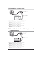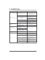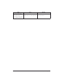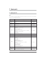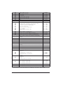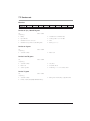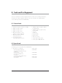
1
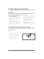
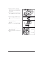
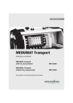
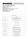
MEDUMAT Easy
Ventilator
Servicing and repair instructions
WM 28000
Contents
Introduction . . . . . . . . . . . . . . . . . . . . . . . . . . 3
1. Overview . . . . . . . . . . . . . . . . . . . . . . . . . . . 4
1.1 Special symbols on the ventilator . . . . . . 5
2. Description . . . . . . . . . . . . . . . . . . . . . . . . . .
2.1 Uses. . . . . . . . . . . . . . . . . . . . . . . . .
2.2 Ventilation function . . . . . . . . . . . . . . .
2.3 Demandflow function . . . . . . . . . . . . . .
2.4 Patient valve . . . . . . . . . . . . . . . . . . .
2.5 Audio response . . . . . . . . . . . . . . . . .
6
6
6
7
7
7
3. Final check . . . . . . . . . . . . . . . . . . . . . . . . . . 8
3.1 Testing equipment required . . . . . . . . . . 8
3.2 Preparing for final check . . . . . . . . . . . 8
3.3 Entering the device data . . . . . . . . . . . 8
3.4 Testing for leaks and pressure reading . . 9
3.5 Self-test when device is switched on . . . . 9
3.6 Functional check on controls
(button check). . . . . . . . . . . . . . . . . . . 9
3.7 Functional test and alarms . . . . . . . . . 10
3.8 Battery power . . . . . . . . . . . . . . . . . 10
3.9 Test pressure sensors . . . . . . . . . . . . . 11
3.10 Functional check on frequency setting . . 12
3.11 Functional check breath volume
at 4.5 bar input pressure and
10 mbar back pressure . . . . . . . . . . . 12
3.12 Checking O2 concentration . . . . . . . . 13
3.13 Functional check on pressure limit . . . . 13
3.14 Functional check on relief valve
without patient valve . . . . . . . . . . . . . 13
3.15 Checking the type plate data . . . . . . . 13
3.16 Check on external condition . . . . . . . . 14
3.17 Documentation . . . . . . . . . . . . . . . . . 14
4. Servicing . . . . . . . . . . . . . . . . . . . . . . . . . . . 15
4.1 Intervals and scope . . . . . . . . . . . . . . 15
4.2 Batteries . . . . . . . . . . . . . . . . . . . . . 16
4.3 Storage . . . . . . . . . . . . . . . . . . . . . 16
5. Troubleshooting . . . . . . . . . . . . . . . . . . . . . . 17
6. Repair information and instructions . . . . . . . 20
6.1 General . . . . . . . . . . . . . . . . . . . . . 20
6.2 Changing the filter in the pressurised
gas connection . . . . . . . . . . . . . . . . 20
6.3 Opening the device . . . . . . . . . . . . . 21
6.4 Closing the device . . . . . . . . . . . . . . 22
6.5 Replacing button cell . . . . . . . . . . . . . 24
6.6 Changing the speaker . . . . . . . . . . . . 25
6.7 Changing the board . . . . . . . . . . . . 26
6.8 Replacing the pneumatic block . . . . . . 27
6.9 Replacing the 3/2-way magnetic valve 29
6.10 Calibrating the potentiometer
(after changing pneumatic block
including potentiometer) . . . . . . . . . . . 30
6.11 Changing upper part of housing . . . . . 31
6.12 Changing the fascia film . . . . . . . . . . 32
6.13 Changing lower part of housing . . . . . 33
7. Spare parts . . . . . . . . . . . . . . . . . . . . . . . . . 35
7.1 Spare parts list . . . . . . . . . . . . . . . . . 35
7.2 Service sets . . . . . . . . . . . . . . . . . . . 37
8. Tools and Test Equipment . . . . . . . . . . . . . . . 38
8.1 General tools . . . . . . . . . . . . . . . . . . 38
8.2 Special tools . . . . . . . . . . . . . . . . . . 38
8.3 Testing equipment. . . . . . . . . . . . . . . 39
9. Technical data . . . . . . . . . . . . . . . . . . . . . . . 40
9.1 Pneumatic / electronic systems . . . . . . 41
10. Technical Changes . . . . . . . . . . . . . . . . . . . 42
11. Repair and service records . . . . . . . . . . . . . . 43
© Copyright WEINMANN GmbH & Co. KG.
The content and presentation are copyright protected and may only be used by authorised WEINMANN Service Partners in
the course of their service operations. The content must not be reproduced or passed on to third parties. The complete documents
must be returned on termination of the cooperation with WEINMANN.
2
Introduction
For decades WEINMANN has been developing,
manufacturing and marketing devices for emergency medical care, oxygen therapy and inhalation
therapy.
In 1972 WEINMANN put the first MEDUMAT
emergency respirator on the market.
MEDUMAT emergency respirators are automatic
respirators. They are used for controlled respiration
in emergency medical care, e.g. in cases of acute
respiratory disorders, and also secondary obstructions.
The new generation of devices, developed specifically to meet users’ requirements and put on the
market in 1997, offers users and patients increased security. An intelligent alarm system monitors the patient’s breathing and informs the user
about any problems that occur. These devices thus
offer even greater security and reliability during
respiration.
The aim of these servicing and repair instructions is
to familiarise you, as an expert in the field, with the
function, technology, servicing and repair of the
MEDUMAT respirator. Thanks to training which you
have already received from WEINMANN, you now
count as “trained expert personnel” and can therefore give your customers appropriate instructions,
remedy problems on your own and perform the
functional checks prescribed in the operating instructions and any repairs required in accordance with
these Service and Repair Instructions.
In the event of a warranty claim, send the MEDUMAT
to WEINMANN.
To enable us to process ex gratia requests or warranty claims, please enclose the customer’s proof
of purchase (invoice) with the device.
Repairs or servicing work may be performed only
by WEINMANN or by trained specialist staff.
You are responsible for repairs carried out yourself
and for their warranty!
Use only original WEINMANN spares for repairs.
Please bear in mind:
Your customer trusts you and relies on your expert
capability, just as you rely on WEINMANN.
Note:
For the following information, please consult the Operating Instructions for MEDUMAT:
•
Safety Information
•
Fitting accessories
•
Operating MEDUMAT emergency respirators
•
Hygienic preparation
•
Functional check
Introduction
3
1. Overview
Control panel MEDUMAT Easy
2 Respiratory pressure
indicator (bar graph)
3 Alarm panel
MEDUMAT
Easy
60
mbar
Stenosis
Disconnection
< 2,7 bar O2
50
4 Alarm confirmation
40
5 Colour code
30
20
10
0
11 12
9
10
10
14
12
13
7 11
6 Adjuster knob, ventilation parameters
14 16
16
5
15
7 Index position
Demandflow
30
8 LED Demandflow
3 Freq.(min-1)
MV (l/min)
1 Mask/tube ventilation
switch with indicator
LEDs
9 ON/OFF switch
Connections MEDUMAT Easy
AT
MEDUM
Easy
10 Pressurized gas
connection
60
Stenosis ction
ne
Discon r O2
< 2,7 ba
mbar
50
40
30
20
10
0
11 12
10 12
9
10
7 11
14
15
13
14 16
16
5
MEDU
Easy
Demand
flow
30
60
MAT
is
Stenos tion
nec
Discon O2
< 2,7 bar
mbar
11 Battery compartment
50
n-1)
mi
3 Freq.(
40
in)
MV (l/m
30
20
11 12
10
0
10 12
9
10
7 11
14
15
13
14 16
Demand
flow
16
5
12 Speaker
30
in-1)
3 Freq.(m
in)
MV (l/m
13 Pressure gauge hose
connection
14 Ventilation hose connection
15 Relief outlet valve
4
Overview
1.1 Special symbols on the ventilator
Symbols on MEDUMAT Easy
MAT
MEDU
Easy
60
te
n hau
Pressio basse
n
Pressio
bar O2
mbar
Typ :
< 2,7
50
Typ :
40
30
20
11 12
10
0
MAT
MEDU
Easy
60
10
14
15
13
14 16
16
is
Stenos tion
nec
Discon O2
< 2,7 bar
mbar
10 12
9
7 11
5
30
3
50
40
30
20
11 12
10
0
10 12
9
10
7 11
14
15
13
14 16
Demand
flow
16
5
30
3 Freq.(m
MV
in-1)
(l/min)
Inlet 2,7 - 6 bar O2.
MEDUMAT Easy device information plate
SN
Serial number of device
Year of manufacture
Do not dispose of device in domestic waste.
Safety check and servicing label
Servicing label: indicates when the next service is due.
Safety check label: (in Germany only) marks when the next safety check as per §6 of the German
law relating to users of medical devices is required.
Overview
5
2. Description
2.1 Uses
MEDUMAT Easy is an automatic oxygen respiration device (short-term ventilator) with additional inhalation
facility.
You can use MEDUMAT Easy:
•
in emergencies;
•
to revive patients at the site of the emergency;
•
•
for longer periods in more protracted
emergencies, e.g. fires;
when transport over considerable distances is
planned.
MEDUMAT Easy:
•
for short-term O2 inhalation using a respiration
mask.
You can use MEDUMAT Easy while transporting
patients:
•
between the various rooms and departments
of a hospital;
•
between the hospital and other premises;
•
is designed to provide controlled ventilation to
persons of 10 kg body weight or more;
•
is used to treat respiratory arrest;
•
can be preset to parameters that ensure evenly
balanced ventilation, provided that the
selected maximum ventilation pressure Pmax is
not exceeded;
•
permits breathing-controlled oxygen inhalation
in Demand mode.
2.2 Ventilation function
MEDUMAT Easy operates within a pressure range
of 2.7 to 6 bar and at a flow rate of not less than
70 l/min O2. It has a built-in power supply.
It uses high-pressure, medicinal-grade oxygen. An
external pressure reducer brings this down to the
required operating pressure. The oxygen supply is
fed in at input valve 10.
AT
MEDUM
Easy
10
60
Stenosis ion
ect
Disconn r O2
< 2,7 ba
mbar
50
40
30
20
10
0
11 12
10 12
9
10
7 11
The ventilation settings are continuously variable.
These settings (frequency and volume per minute
are coupled) and the inspiration/expiration ratio
of 1:1.67 are regulated by internal electronic
control mechanisms.
The gas for inspiration flows along the hose and
through the patient valve and either the mask or
tube into the patient’s airways. The patient valve is
fitted with a lip membrane that enables expired
gas to be conducted away through the expiration
tube.
6
Description
14
15
13
14 16
-
Demand
flow
16
5
30
n-1)
mi
3 Freq.(
in)
MV (l/m
You can check the course of ventilation on the
respiration pressure indicator 2.
60
mbar
50
40
2
30
20
10
9
0
2.3 Demandflow function
The Demandflow setting switches the
MEDUMAT Easy to breathing-controlled O2
inhalation. Such inhalation must be carried out
with the respiration mask. A small inspiration
(trigger) pulse causes oxygen to continue flowing
until slight overpressure interrupts the flow.
Expiration then takes place via the patient valve as
in ventilation.
Demandflow setting
10
11 12
9
0
10
10
13
7 11
5
14
12
15
14 16
16
Demandflow
30
3 Freq.(min-1)
MV (l/min)
2.4 Patient valve
The gas for inspiration is channelled into the
patient’s airways through the patient valve.
38
The valve is designed to enable spontaneous
breathing in the event of failure of the
MEDUMAT Easy.
37
39
40
34
35 36 41
2.5 Audio response
The device has an audio response facility that can
be switched on for user guidance, especially for
users who have little practice.
If audio guidance is not wanted, it can be
switched off by pressing a combination of keys
(see “4.10 Audio response for user guidance” in
the operating instructions).
Description
7
3. Final check
After every repair and every service, the device
must be subjected to the following final check in
accordance with Test Instructions WM 28001
and the test record.
Note:
For the final check on the MEDUMAT Easy you
must connect the ventilation hose and the patient
valve to the device.
We recommend that you always hold reserve
stocks of the following items:
•
replacement washers for the connections;
•
lip membrane for the patient valve.
•
membrane for spontaneous breathing tube;
•
membrane for exhalation tube;
•
O-ring 1145/118.
MEDUMAT Easy must not be used if the final
check reveals defects or deviations from the
specified parameters.
3.1 Testing equipment required
•
Volume flow meter, Type RT 200 (Timeter), Type EKU VIP – ventilator, PF 300 Imtmedical or comparable
test device
•
Adjustable orifice, e.g. ball valve, internal diameter ≥ 10 mm
•
Test set for functional checks WM 15323
•
Oxygen concentration meter, 0 – 100% ± 1%,
e.g. Type Oxycontrol WM 13550
•
Set, hose with syringe WM 15359
•
Pressure gauge
0 - 6.3 bar, class 1.6
•
Pressure gauge
0 -100 mbar, class 1.6
•
Set, supply test Medumat / Modules WM 15440
3.2 Preparing for final check
1. Connect MEDUMAT Easy to the 4.5 - 6 bar pressure supply.
2. Connect ventilation hose and pressure measurement tube to MEDUMAT Easy.
3. Device setting: Freq. = 30 min-1, MV = 3 l/min.
4. Language setting “English”.
3.3 Entering the device data
•
8
Enter the device number and the tester number in the test record.
Final check
3.4 Testing for leaks and pressure reading
3.4.1 Checking input side for leaks
•
With the device switched off, apply 6 bar pressure to input side and and shut off output pressure.
Requirement: The pressure drop must be less than 0.2 bar/min.
3.4.2 Checking pressure measurement zone for leaks
•
Apply 55 mbar ± 2 mbar to MEDUMAT
pressure measurement zone.
MAT
MEDU
Easy
60
Requirement: The pressure drop must be
is
Stenos tion
nec
Discon
bar O2
mbar
< 2,7
50
40
≤ 2 mbar/min.
Test pressure
gauge
30
20
11 12
10
0
10 12
9
10
7 11
14
15
13
14 16
16
5
30
3
13
Respiration
pressure indicator
Syringe
3.5 Self-test when device is switched on
If audio response is enabled, you will hear the sentence “Open oxygen cylinder” before the self-test starts.
1. Apply 4.5 bar to the input.
2. Switch on MEDUMAT Easy at button 9.
Requirement: The self-test starts, the ventilation mode LEDs light up once each one after the other, the alarm
LEDs flash, the pressure indicator LEDs are run through 3 times, a signal tone sounds and an audio
response sentence is spoken.
3.6 Functional check on controls (button check)
1. Open the pressure supply.
2. Switch on the device.
3. Switch from mask ventilation to tube ventilation.
4. Press the alarm acknowledgement button.
Final check
9
3.7 Functional test and alarms
3.7.1 Test Stenosis alarm
•
Switch to tube ventilation (
) and close patient valve outlet.
•
Operate device at Freq. setting = 30 min-1 and MV = 3 l/min.
Requirement: The Stenosis alarm must be triggered after two ventilation cycles. If audio response is
enabled, the ventilator announces “Check airways and minute volume”.
3.7.2 Checking alarm confirmation
•
Immediately after the first alarm tone sounds, press Alarm confirmation button 4.
Requirement: The alarm tone must be suppressed immediately.
3.7.3 Test Disconnection alarm
•
Open patient valve outlet.
Requirement: The Disconnection alarm must be triggered after two ventilation cycles. If audio response
is enabled, the ventilator announces “Check ventilation system and settings”.
3.7.4 Test Pressure alarm
•
Shut off pressurised gas connection of MEDUMAT (2.7 - 6.0 bar).
Requirement: The Pressure alarm must be triggered. If audio response is enabled, the ventilator
announces “Check pressure hose system and gas supply”.
3.7.5 Checking Demand mode LED
•
Open the pressure supply.
Requirement: Demand mode LED must come on (flickering).
3.7.6 Check voice output
3.8 Battery power
3.8.1 3.0 V battery (on board)
Since the 3.0 V lithium cell is difficult to access, its
charge status can be checked both via the
interface and in a relevant menu.
Bar graph value (mbar)
Battery voltage (V)
60
3.21
55
3.19
To do so, hold down the alarm confirmation button
while switching the device on. The device is then
in battery check mode for 3 seconds, before
switching to normal operating mode.
50
3.17
45
3.15
40
3.13
35
3.11
During this 3-second period the “Power supply”
alarm in the alarm panel lights up and the voltage
measured for the lithium cell is shown on the
pressure bar graph.
30
3.09
25
3.07
20
3.05
15
3.03
The adjacent table shows how the voltage
readings correspond to the bar graph values.
10
3.01
5
2.99
0
2.97
10
Final check
Requirement: Voltage measured for 3.0 V battery is in the range 3.0 to 3.2 V; the alarm for this cell is
triggered at 2.7 V.
3.8.2 3.6 V battery (battery compartment)
Remove the 3.6 V battery from the battery compartment and measure the voltage with a digital multimeter.
Requirement: Voltage measured for 3.6 V battery is in the range 3.4 to 3.7 V.
3.9 Test pressure sensors
3.9.1 Input pressure sensor
•
Shut off pressurised gas connection of MEDUMAT (2.7 - 6.0 bar).
Requirement: The Pressure alarm must be triggered. If audio response is enabled, the ventilator
announces “Check pressure hose system and gas supply”.
3.9.2 Ventilation pressure sensor
•
Connect ventilation hose to test bag.
•
Run device with settings: Freq. = 10 min-1 and MV = 11 l/min.
•
Switch device to mask ventilation.
Requirement: The pressure limit must respond at 20 ± 5 mbar.
•
Switch device to tube ventilation.
Requirement: The pressure limit must respond at 45 ± 5 mbar.
3.9.3 Demand flow sensor
1. Supply device with pressure.
2. Switch on MEDUMAT Easy at button 9.
3. Connect ventilation tube and patient valve to test bag.
4. Set MEDUMAT Easy to demand flow mode.
5. Green LED in demand mode button illuminates.
6. Squeeze the test bag.
Requirement: Releasing the test bag triggers a short ventilation.
Final check
11
3.10 Functional check on frequency setting
MAT
MEDU
Easy
osis
Sten ection
Disconn
bar O2
mbar
60
< 2,7
Patient valve with
hose system
50
40
30
20
11 12
10
10 12
9
0
10
7 11
14
15
13
14 16
16
5
30
3
Volume flow meter
Orifice 10 mbar
open
•
Connect ventilation hose to 10 mbar orifice and to volume flow meter.
•
Run device with settings: Freq. = 14 min-1 and MV = 16 l/min.
Requirement: The frequency must be 14 ± 2 min-1.
•
Run device with settings: Freq. = 10 min-1 and MV = 11 l/min.
Requirement: The frequency must be 10 ± 2 min-1.
•
Run device with settings: Freq. = 30 min-1 and MV = 3 l/min.
Requirement: The frequency must be 30 ± 2 min-1.
3.11 Functional check breath volume at 4.5 bar input pressure and
10 mbar back pressure
MAT
MEDU
Easy
60
osis
Sten ection
Disconn
bar O2
mbar
< 2,7
Patient valve with
hose system
50
40
30
20
10
0
11 12
14
10 12
9
15
10
13
14 16
7 11
16
5
30
3
Volume flow meter
Orifice at 10 mbar
setting
•
Run device with settings: Freq. = 14 min-1 and MV = 16 l/min.
Requirement: Breath volume must be 1140 ± 170 ml.
•
Run device with settings: Freq. = 10 min-1 and MV = 11 l/min.
Requirement: Breath volume must be 1100 ± 170 ml.
•
Run device with settings: Freq. = 30 min-1 and MV = 3 l/min.
Requirement: Breath volume must be 100 ± 20 ml.
12
Final check
3.12 Checking O2 concentration
•
Run device with settings: Freq. = 10 min-1, MV = 11 l/min and 100% O2.
Requirement: The O2 concentration must be > 98%.
3.13 Functional check on pressure limit
•
Connect ventilation hose to test bag.
•
Run device with settings: Freq. = 10 min-1 and MV = 11 l/min.
•
Switch device to mask ventilation.
Requirement: The pressure limit must respond at 20 ± 5 mbar.
•
Switch device to tube ventilation.
Requirement: The pressure limit must respond at 45 ± 5 mbar.
3.14 Functional check on relief valve without patient valve
•
Run device with settings: Freq. = 11min-1 and MV = 7 l/min.
•
Switch ventilation hose to test bag.
Requirement: The test bag is fully inflated during the inspiration stroke. The ventilator is then heard to
release pressure.
3.15 Checking the type plate data
•
Check type plate data against drawing.
Requirement: The type plate data must be correctly entered in accordance with the drawing.
Final check
13
3.16 Check on external condition
•
Check external condition.
Requirements: The outside of the device is not scratched and there are no flaws.
The connection thread is undamaged and screws easily.
The adjuster knob is secured by self-locking against inadvertent changes.
Elbow outlet turns easily.
3.17 Documentation
•
14
Document items 3.3 to 3.16, and also test date and tester number, in the test record.
Final check
4. Servicing
Note:
Remember to perform a final check after every repair.
We recommend that maintenance work such as inspections and repairs be performed only by the
manufacturer, i.e WEINMANN, or by qualified technicians expressly authorized by WEINMANN.
4.1 Intervals and scope
Every 2 years:
Every 2 years the device (incl. patient valve and hose system) must undergo servicing and be subjected to a
safety check as specified below.
You can also have servicing and the safety check performed by WEINMANN.
Be sure to check the following items:
•
Check equipment for completeness;
•
Visual check:
– Mechanical damage
– Labelling of controls
– Damage to all external hoses;
•
Renew parts subject to wear / parts requiring
compulsory replacement (see “7.2 Service
sets” on page 37);
•
Check system components: carrying platforms,
oxygen fittings, secretion suction system, hose
connections etc.;
•
Check test bag;
•
Final check in accordance with Test Instructions/
Test Record STK WM 28001 (see “3. Final check”
on page 8 and see “11. Repair and service
records” on page 43).
Every 4 years:
•
Servicing of the fittings in the oxygen supply system (e.g. pressure reducer) either by the manufacturer or
by a specialist expressly authorized by the manufacturer.
Every 10 years:
•
Repeat testing of conventional steel or aluminium oxygen cylinders by the responsible testing
organisation. The repeat testing date is stamped on the shoulder of the cylinder.
Servicing
15
4.2 Batteries
MEDUMAT Easy is equipped with two batteries.
The main battery 18 must always be changed. The
button cell 17 (CR2430) only has to be replaced
every 4 years.
17
The button cell 17 supplies auxiliary power to the
electronic system if the main battery 18 fails. This
makes it possible to set off an alarm even if the
main battery suddenly fails. The device then
switches to exhalation.
In principle, the battery capacity is designed so
that under normal conditions of use, it will not need
changing in the 2 years between services. The
main battery 18 is to be renewed during the 2yearly service, the button cell 17 only every 4
years.
When changing batteries, special precautions
must be taken to protect the electronic circuits (see
“6.5 Replacing button cell” on page 24).
When changing the main battery 18, you must
change the O-ring 42 on the battery compartment
cover as well.
42
60
MEDUMA
T
Easy
mbar
Stenos
is
Disconn
ecti
< 2,7 bar on
O
50
40
2
30
20
10
0
11 12
9
10
7 11
5
10
12
14
18
13 15
14
16
16
30
3 Freq
.(mi
n-1)
MV (l/m
in)
Demand
flow
17: Button cell for back-up power
18: Lithium battery 3.6 V for main power
supply MEDUMAT Easy
4.3 Storage
If you do not intend to use MEDUMAT Easy for a long period, we recommend the following storage
precautions:
1. Clean and disinfect the device (see “5.
Hygienic Preparation” in the operating
instructions).
2. Store MEDUMAT Easy in a dry place.
16
Servicing
Important
Remember that devices still require servicing at the
specified intervals even when in storage, otherwise
they are not allowed to be used when removed
from storage.
5. Troubleshooting
Fault
MEDUMAT Easy does not
start up when switched on
MEDUMAT Easy will not
switch off
MEDUMAT Easy is
functioning, but without any
displays
Cause
Remedy
A battery is exhausted
Change main battery 18 (4.2,
page 16), check button cell 17
(3.8.1, page 10) and replace if
necessary (4.2, page 16)
Fuse defective
Change board (6.7, page 26)
Check plug-in connection and cable
Ribbon cable X100 of fascia film is (6.7, page 26)
faulty or not connected
If necessary, replace upper part of
housing (6.11, page 31)
On/Off button 9 defective
Change fascia film (6.12, page 32)
Board defective
Change board (6.7, page 26)
Magnetic valve defective
Change magnetic valve (6.9,
page 29)
Operating error
Keep On/Off button 9 pressed for
at least 2 seconds
On/Off button 9 defective
Change fascia film (6.12, page 32)
Pressure gauge hose on
MEDUMAT Easy or on patient valve
has slipped off
Kink in pressure gauge hose
Check pressure gauge hose
Pressure gauge hose within device is
kinked or has slipped off
MV too high
Measured without 10 mbar back
pressure
Set to 10 mbar back pressure
Measuring device not calibrated
Calibrate measuring device
Input pressure > 6 bar
Reduce system setting to less than
6 bar
Patient valve not in order
Check membranes and O-ring,
replace if necessary (Chapter 6.7 of
operating instructions)
Potentiometer wrongly adjusted
Readjust potentiometer (6.10,
page 30)
Adjuster knob out of adjustment
Readjust adjuster knob (6.10,
page 30)
Pneumatic block leaking
Replace pneumatic block (6.8,
page 27)
MV not correct
Troubleshooting
17
Fault
Cause
Remedy
Incorrect setting selected on device
Make correct setting (Chapter 6.5 of
operating instructions)
Patient valve not in order
Check membranes and O-ring,
replace if necessary (Chapter 6.7 of
operating instructions)
Patient valve or test bag not correctly Check hose connections and test
connected
bag
Pressure limit (Pmax) not in
order
MV not in order
See fault “MV not in order”
Hose connections in device not in
order
Check hoses, replace if necessary
(6.8, page 27)
Pressure sensor on board is faulty
Change board (6.7, page 26)
Adjuster knob for ventilation
defective
Replace adjuster knob (6.3,
page 21 and 6.4, page 22)
Pressure measurement connection
blocked
Replace (6.8, page 27)
LED’s do not light up
Change board (6.7, page 26)
Alarms (visual + acoustic) not
Incorrect indication (Stenosis/
in order
Disconnection)
Check settings, check hose
connection to patient valve (Chapter
6.7 of operating instructions)
No (visual + acoustic) alarm
Board defective
Change board (6.7, page 26)
Alarm confirmation pressed?
Wait for between 30 – 120 s
Speaker defective
Replace speaker (6.6, page 25)
Pressure sensor defective
Change board (6.7, page 26)
Hose connections in device not in
order
Check hoses, replace if necessary
(6.8, page 27)
Battery failing
Change main battery 18 (4.2,
page 16), check button cell 17
(3.8.1, page 10) and replace if
necessary (4.2, page 16)
No acoustic alarm
Alarm < 2.7 bar although
pressure present
+ – alarm.
Pressure inlet leaking
Angled connector in device is loose
Check (6.8, page 27)
or defective
Hose system in device is
leaking
Check hoses, replace if necessary
(6.8, page 27)
Pressure sensor on board is
leaking
Change board (6.7, page 26)
Mask/tube switch 1 defective
Change fascia film (6.12, page 32)
Pneumatic block leaking
Replace pneumatic block (6.8,
page 27)
Potentiometer wrongly adjusted
Adjust potentiometer (6.10,
page 30)
Potentiometer defective
Replace pneumatic block (6.8,
page 27)
Frequencies not in order
Test bag is not filled
sufficiently during functional
check, Disconnection alarm
18
Troubleshooting
Ventilation parameters incorrectly set Correct ventilation parameters
Patient valve not working properly
Check lip membrane
Pressure measurement tube not fitted Fit pressure measurement tube
Fault
Cause
No Stenosis alarm when
patient valve closed during
functional check (see
Patient valve not working properly
“Checking the breath volume”
in the operating instructions)
Remedy
Check lip membrane
Troubleshooting
19
6. Repair information and instructions
6.1 General
Always perform repairs to MEDUMAT Easy at an ESD-protected workplace.
•
Observe the safety information in the Operating
Instructions for MEDUMAT Easy.
•
Be sure to carry out a final check after every
repair (see “3. Final check” on page 8).
•
All operations on this device require detailed
knowledge and observation of the Operating
Instructions and the Service and Repair
Instructions.
•
If you replace components or individual parts,
use only genuine WEINMANN parts.
•
When ordering the lower part of the
housing 24, please specify device type, year
of manufacture and device number.
•
Note:
•
•
Do not carry out any repairs that are not
described in these Service and Repair
Instructions. This is the only way to guarantee
trouble-free functioning of MEDUMAT Easy.
Make sure that your hands and workplace are
clean during the repair work.
The item numbers quoted in the following text
are identical to the item numbers in the spare
parts list on Page 35 and the overview on
Page 4.
6.2 Changing the filter in the pressurised gas connection
Tools and equipment required
•
Flat-head screwdriver
•
Tweezers.
1. Unscrew the slot-head screw from the
pressurised gas connection 10.
2. Use tweezers to remove filter set 57.
3. Carefully insert a new filter set 57 in the
pressurised gas connection.
4. Screw the slot-head screw firmly into the
pressurised gas connection.
20
Repair information and instructions
57
6.3 Opening the device
Tools and equipment required
•
ESD-protected workplace,
•
Phillips screwdriver, size 1,
•
Tubular hexagon box spanner 10 mm,
•
Special tool WM 22829 from special tool set WM 15349,
•
Flat-nose pliers.
1. Open the battery compartment with a coin
and remove the battery.
60
MEDUMA
T
Easy
mbar
Stenosis
Disconn
ecti
< 2,7 bar on
O2
50
40
30
20
10
0
11 12
9
10
7 11
5
10
12
14
13 15
14
16
16
30
Demand
flow
3 Freq
.(min-1
)
MV (l/m
2. Lift off the lid 32.
11 12
10
10 12
9
0
3. Hold the adjuster knob 33 still with the special
tool and loosen the nut with a tubular hexagon
socket spanner (10 mm).
in)
10
7 11
14
15
13
14 16
5
33
dDeman
flow
16
30
32
in )
-1
3 Freq.(m
)
min
MV (l/
Do not unscrew the nut completely – only loosen
it. Otherwise the knob will split into its separate
parts.
4. Pull off the adjuster knob 33.
5. Place the device on a non-slip surface and
unscrew the 4 screws 43 from the rear of the
device.
43
24
43
6. Place the device on its side and carefully pull
the two parts of the housing apart until the
locating pin of the adjuster knob is pulled
completely out of the upper part of the
housing 20.
60
MEDUM
Easy AT
mbar
Stenosis
Discon
nec
< 2,7 ba tion
r O2
50
40
30
24
20
7. Remove the speaker 12 from the lower part of
the housing 24 and disconnect it.
10
0
11 12
9
10
7 11
5
10
12
14
13 15
14
16
16
30
3 Fre
q.(mi
MV (l/m
n-1)
Demand
flow
in)
12
20
Repair information and instructions
21
8. Disconnect the plug of wiring harness 51 from
the board.
Earth connection
Note:
This is best done with flat-nose pliers. Be very
careful not to damage the board with the
pliers.
9. Unscrew the blue sensor tube 53 from the
pneumatic block.
Note:
Do NOT pull sensor tube 53 off the pressure
sensor on the board, as this will damage the
sensor.
10. Pull the ends of the Y-shaped sensor tube 54 off
the sensors on the board.
11. Flap the two parts of the housing apart and
place them with the outside downwards.
54
53
46
12. Unscrew screw 47 with the serrated washer 48
from the earth connection to the pneumatic
block.
13. Unscrew the two screws 46 with the spring
washers 45 and remove the battery contacts
from the battery compartment.
45
The two halves of the housing are now
separated.
6.4 Closing the device
Tools and equipment required
•
ESD-protected workplace,
•
Torque spanner 50 ±5 Ncm,
•
Torque spanner 200 ±10 Ncm,
•
Tubular hexagon box spanner 10 mm,
•
Special tool WM 22829 from special tool set WM 15349,
•
Allen key SW 2.5.
1. Place the two parts of the housing side by side
with the outside facing downwards.
46
2. Place the battery contacts in the battery
compartment and screw them in place with the
two screws 46 and the spring washers 45.
45
22
Repair information and instructions
51
48 47
3. Push the ends of the Y-shaped sensor tube 54
onto the sensors on the board.
Earth connection
4. Screw the blue sensor tube 53 onto the
pneumatic block.
5. Connect the plug of wiring harness 51 to the
board.
6. Attach the earth connection to the pneumatic
block using screw 47 and serrated washer 48.
54
7. Connect up the speaker 12 and insert it in the
recess in the lower part of the housing 24. The
centering lug of the speaker must be located in
the corresponding groove in the lower part of
the housing.
60
53
51
48 47
MEDUM
Easy AT
mbar
Stenosis
Discon
nec
< 2,7 ba tion
rO
50
40
2
30
24
20
8. Push the adjuster knob locating pin through the
hole in the board and put the two halves
together.
10
0
11 12
9
10
7 11
5
10
12
14
13 15
14
16
16
30
3 Fre
q.(mi
MV (l/m
n-1)
Demand
flow
in)
20
9. Insert the battery in the battery compartment
and close the lid with a coin. Make sure the
battery is correctly connected.
60
Centering
lug
12
MEDUMA
T
Easy
mbar
Stenosis
Disconn
ecti
< 2,7 bar on
O2
50
40
30
20
10
0
11 12
9
10
7 11
5
10
12
14
13 15
14
16
16
30
3 Freq
.(mi
MV (l/m
Demand
flow
n-1)
in)
10. Now screw up the lower part of the housing
with the 4 screws 43 using a torque of
50 ±5 Ncm.
43
24
43
11. Secure the adjuster knob 33:
– Push the adjuster knob onto the spindle as
far as it will go, then pull it out a fraction.
– Hold the knob firm with the special tool and
screw it tight with a torque of
200 ±10 Ncm.
10
0
11 12
10 12
9
10
7 11
14
15
13
14 16
dDeman
flow
16
5
30
in
3 Freq.(m
)
-1
33
32
)
min
MV (l/
Repair information and instructions
23
12. Check the alignment of the adjuster knob.
When the knob is turned fully to the left, the
white line must point to MV: 3 l/min.
If it does not, slacken the nut and realign the
adjuster knob.
13. Place the cap 32 on the adjuster knob 33.
14. Perform the final check (see “3. Final check” on
page 8).
6.5 Replacing button cell
Tools and equipment required
•
ESD-protected workplace,
•
Phillips screwdriver, size 1,
•
Tubular hexagon box spanner 10 mm,
•
Torque spanner 50 ±5 Ncm,
•
Torque spanner 200 ±10 Ncm,
•
Special tool WM 22829 from special tool set WM 15349,
•
Flat-nose pliers.
1. Open the device (see “6.3 Opening the
device” on page 21).
2. Release the ribbon cable from its clamp X100:
To do so, lift up the top part of the clamp. Then
you can pull out the cable.
49
21
3. Unscrew the two screws 49 and remove the
board 21 from the upper part of the housing.
X100
49
4. To remove the button cell 17, use a match or
similar to ease it slightly out of the holder and
pull the button cell out sideways with the other
hand.
Caution!
Do not use sharp or pointed objects for this
purpose, as this could damage the board.
5. Insert a new button cell 17.
Make sure it is installed the right way round.
24
Repair information and instructions
Push here
17
6. Insert the board 21 in the upper part of the
housing.
49
21
Make sure that the ribbon cable is not under the
board or jammed between it and the housing.
7. Attach the board 21 with the two screws 49.
8. Place the ribbon cable in the clamp X100 on
the board and then press down the top part of
the clamp.
X100
49
9. Close the device (see “6.4 Closing the
device” on page 22). Use a new main
battery 18.
10. Perform a final check (see “3. Final check” on
page 8).
Please remember that old batteries must not be disposed of in household waste. Always take old batteries
to a local collection point.
6.6 Changing the speaker
Tools and equipment required
•
ESD-protected workplace,
•
Phillips screwdriver, size 1,
•
Tubular hexagon box spanner 10 mm,
•
Torque spanner 50 ±5 Ncm,
•
Torque spanner 200 ±10 Ncm,
•
Special tool WM 22829 from special tool set WM 15349.
1. Open the device (see „6.3 Opening the
device“ on page 21, steps 1. to 6.).
2. Remove the speaker 12 from the lower part of
the housing 24 and disconnect the speaker
cable plugs. Put the old speaker on one side.
60
3. Take the new speaker 12 and connect the
speaker cable plugs.
MEDUM
Easy AT
mbar
Stenosis
Discon
nec
< 2,7 ba tion
r O2
50
40
30
24
20
10
4. Insert the speaker 12 in the recess in the lower
part of the housing 24. The centering lug of the
speaker must be located in the corresponding
groove in the lower part of the housing.
5. Close the device (see „6.4 Closing the
device“ on page 22, steps 8. to 13.).
0
11 12
9
10
7 11
5
10
12
14
13 15
14
16
16
30
3 Fre
q.(mi
MV (l/m
n-1)
Demand
flow
in)
20
12
Centering
lug
6. Perform the final check (see “3. Final check” on
page 8).
Repair information and instructions
25
6.7 Changing the board
Tools and equipment required:
•
ESD-protected workplace,
•
Phillips screwdriver, size 1,
•
Tubular hexagon box spanner 10 mm,
•
Torque spanner 50 ±5 Ncm,
•
Torque spanner 200 ±10 Ncm,
•
Special tool WM 22829 from special tool set WM 15349,
•
Flat-nose pliers.
1. Open the device (see “6.3 Opening the
device” on page 21).
2. Release the ribbon cable from its clamp X100:
To do so, lift up the top part of the clamp. Then
you can pull out the cable.
49
21
3. Unscrew the two screws 49 and remove the
board 21 from the upper part of the housing.
4. Place the new board 21 on the spacers.
Make sure that the ribbon cable is not under the
board or jammed between it and the housing.
X100
49
5. Attach the board 21 with the two screws 49.
6. Place the ribbon cable in the clamp X100 on
the board and then press down the top part of
the clamp.
49
21
7. The screw of the blue sensor tube 53 is secured
with a nut for transport. Remove the nut before
screwing the tube to the pneumatic block
8. Close the device (see “6.4 Closing the
device” on page 22).
9. Perform a final check (see “3. Final check” on
page 8).
26
Repair information and instructions
53
X100
49
6.8 Replacing the pneumatic block
Tools and equipment required:
•
ESD-protected workplace,
•
Phillips screwdriver, size 2,
•
Tubular hexagon box spanner 10 mm,
•
Torque spanner 50 ±5 Ncm,
•
Torque spanner 200 ±10 Ncm,
•
Special tool WM 22829 from special tool set WM 15349,
•
Flat-nose pliers.
1. Open the device (see “6.3 Opening the
device” on page 21).
2. Press the catch and unplug the magnetic valve
control cable.
3. Unplug the potentiometer cable.
Potentiometer
cable
Magnetic valve
control cable
4. Remove the clip 27 from the pneumatic
block 22.
5. Pull the elbow connector 26 off the pneumatic
block 22.
22
27
26
6. Turn the lower part of the housing over, hold it
and the pneumatic block tight and unscrew
both screws 44 together with the spring
washers 45.
56
Catch
45
44
7. Turn the lower part of the housing over again.
8. Press the catch towards the elbow connector
and pull the pneumatic block 22 off the
tube 56.
When you remove the pneumatic block from
the lower part of the housing, the O-ring 28
will fall out of the connection. Make sure that
the O-ring 31 does not fall out of the relief
outlet valve.
22
28
31
Repair information and instructions
27
9. When inserting the new or replacement
pneumatic block 22, insert the tube 56 in the
elbow connector. Make sure that the cables
are routed below the pneumatic block to the
right-hand side.
56
45
44
10. Turn the lower part of the housing over, hold it
and the pneumatic block tight and screw up
both screws 44 with their spring washers 45.
22
Cable
11. Lubricate the O-rings of the elbow connector
26 with a little O2 lubricant (WM 14298).
Make sure that the compensating hole remains
free.
26
Compensating
hole
12. Insert the O-ring 28 in the groove in the outlet
from the pneumatic block.
13. Insert the elbow connector 26 in the pneumatic
block 22.
14. Insert the clip 27 in the pneumatic block 22.
22
27
28
26
15. Plug in the potentiometer cable.
16. Plug in the magnetic valve control cable.
17. Close the device (see “6.4 Closing the
device” on page 22).
18. Perform a final check (see “3. Final check” on
page 8).
Potentiometer
cable
Magnetic valve
control cable
28
Repair information and instructions
6.9 Replacing the 3/2-way magnetic valve
Tools and equipment required:
•
ESD-protected workplace,
•
Phillips screwdriver, size 2,
•
Phillips screwdriver, size 0,
•
Tubular hexagon box spanner 10 mm,
•
Torque spanner 50 ±5 Ncm,
•
Torque spanner 200 ±10 Ncm,
•
Special tool WM 22829 from special tool set WM 15349,
•
Flat-nose pliers.
1. Open the device (see “6.3 Opening the
device” on page 21).
2. Remove the pneumatic block (see “6.8
Replacing the pneumatic block” on page 27).
3. Place the pneumatic block on the side with the
type plate.
4. Unscrew the two securing screws and remove
the 3/2-way magnetic valve 23.
5. Insert the new 3/2-way magnetic valve 23 in
the correct position.
23
Make sure that the seal for the 3/2-way magnetic
valve is seated in the correct position.
6. Fasten the 3/2-way magnetic valve with the
screws supplied with it.
7. Reinstall the pneumatic block (see “6.8
Replacing the pneumatic block” on page 27).
8. Close the device (see “6.4 Closing the
device” on page 22).
9. Perform a final check (see “3. Final check” on
page 8).
Repair information and instructions
29
6.10 Calibrating the potentiometer
(after changing pneumatic block including potentiometer)
When the pneumatic block including potentiometer is changed, the potentiometer must be recalibrated for
the board.
1. Make sure the device is switched off.
2. Press the On/Off switch 9 and immediately
hold down the alarm confirmation button 4
and the mask/tube ventilation switch 1. Then
release the button. After a brief interval, the 30
mbar LED on the bar graph indicator lights up.
MEDUMAT
Easy
60
6. Press the mask/tube switch 1. The device
accepts this value The LED on the bar graph
lights up, and you can move on to setting the
next value.
7. Turn the adjuster knob 6 back beyond the
index point 7 to the ventilation mode zone,
then to the right again until it reaches the index
point (zone MV 16, Freq. 14 ).
8. Press the mask/tube switch 1 again. The
calibration values are stored and the device
exits the calibration mode.
Note:
Until the last step the calibration mode can be
cancelled at any time by pressing the On/Off
switch 9, without storing the new values. If an
invalid value is detected during calibration (all
alarm LEDs light up), no value is stored either.
30
Repair information and instructions
4
40
30
20
10
0
11 12
9
10
4. Press the mask/tube switch 1. The device now
makes a plausibility check.
5. Turn the adjuster knob 6 fully to the right to the
white Demandflow zone.
Stenosis
Disconnection
< 2,7 bar O2
50
3. To set the first calibration value, turn the
adjuster knob 6 fully to the left to the value
MV 3, Freq. 30.
– If the value is not correct, all alarm LEDs light
up until the correct value is present at the
adjuster knob 6 and has been confirmed
with the mask/tube ventilation switch 1. Or
you can cancel the potentiometer
calibration process by pressing the On/Off
switch 9.
– If the value is correct, this is indicated by the
0 mbar LED on the bar graph lighting up.
You can now set the next value.
mbar
10
5
14
12
13
7 11
15
6
14 16
16
30
Demandflow
7
3 Freq.(min-1)
1
MV (l/min)
9
6.11 Changing upper part of housing
Tools and equipment required:
•
ESD-protected workplace,
•
Phillips screwdriver, size 2,
•
Tubular hexagon box spanner 10 mm,
•
Torque spanner 50 ±5 Ncm,
•
Torque spanner 200 ±10 Ncm,
•
Special tool WM 22829 from special tool set WM 15349,
•
Flat-nose pliers.
1. Open the device (see “6.3 Opening the
device” on page 21).
2. Remove the board (see „6.7 Changing the
board“ on page 26, steps 2. and 3.).
3. Remove the grommet 52 from the upper part of
the housing 20.
20
52
You have now removed all the parts. You can start
reassembling.
4. Insert the grommet 52 in the new upper part of
the housing 20.
5. Refit the board (see „6.7 Changing the board“
on page 26, steps 4. to 6.).
6. Close the device (see “6.4 Closing the
device” on page 22).
7. Perform a final check (see “3. Final check” on
page 8).
Repair information and instructions
31
6.12 Changing the fascia film
Tools and equipment required:
•
ESD-protected workplace,
•
Phillips screwdriver, size 2,
•
Tubular hexagon box spanner 8 mm,
•
Tubular hexagon box spanner 10 mm,
•
Torque spanner 50 ±5 Ncm,
•
Torque spanner 200 ±10 Ncm,
•
Special tool WM 22829 from special tool set WM 15349,
•
Flat-nose pliers.
1. Open the device (see “6.3 Opening the
device” on page 21).
2. Remove the board (see „6.7 Changing the
board“ on page 26, steps 2. and 3.).
3. Remove the grommet 52 from the upper part of
the housing 20.
20
52
4. From inside the housing, insert the tubular box
spanner through the hole for the grommet 52
and press the fascia film 19 outwards until you
can grasp it on one side. Then completely
remove the fascia film from the upper part of
the housing.
19
20
5. Use 70% isopropanol to remove all traces of
adhesive from the upper part of the housing.
Then wait until the isopropanol has completely
evaporated from the housing surface.
You have now removed all the parts. You can start
reassembling.
6. Stick the new fascia film 19 to the upper part
of the housing:
– First position the fascia film on the upper
part of the housing on the side where the
ribbon cable is attached.
– Run the ribbon cable through the slit in the
upper part of the housing.
– Then affix the entire fascia film, taking care
to avoid bubbles.
32
Repair information and instructions
60
MEDUMAT
Easy
mbar
Stenosis
Disconnection
< 2,7 bar
O2
50
40
30
20
10
19
0
11 12
9
10
7 11
5
10
12
Ribbon
cable
14
13 15
14 16
16
30
3 Freq.(mi -1
n )
MV (l/min)
Demandflow
7. Refit the grommet 52 in the upper part of the
housing 20.
8. Refit the board (see „6.7 Changing the board“
on page 26, steps 4. to 6.).
9. Close the device (see “6.4 Closing the
device” on page 22).
20
52
10. Perform a final check (see “3. Final check” on
page 8).
6.13 Changing lower part of housing
Tools and equipment required:
•
ESD-protected workplace,
•
Phillips screwdriver, size 2,
•
Open-ended spanner, 13 mm,
•
Open-ended spanner, 22 mm,
•
Torque spanner 50 ±5 Ncm,
•
Torque spanner 200 ±10 Ncm,
•
Special counter tool G 3/8 (WM 22827) and special spanner 17 mm (WM 22828) from special tool
set WM 15349,
•
Vice with jaw protectors,
•
Flat-nose pliers.
1. Open the device (see “6.3 Opening the
device” on page 21).
2. Remove the pneumatic block (see „6.8
Replacing the pneumatic block“ on page 27,
steps 2. to 8.).
3. Undo the screws 50 and remove the wiring
harness 51.
50
24
51
4. Use a pointed object to push the blanking plug
59 of the interface connection out of the lower
part of the housing 24 from inside.
59
5. Remove the O-ring 31 from the lower part of
the housing 24.
24
31
Repair information and instructions
33
6. Screw the special counter tool onto the
pressurised gas connection 10.
7. Clamp the special counter tool in a vice.
10
8. Use a 22-mm open-ended spanner to screw
the nut of the special counter tool firmly again
the pressurised gas connection.
10
24
9. Screw the elbow connector 25 off with a
13-mm open-ended spanner.
10. Use the 17-mm special spanner to slacken the
nut 30 and unscrew it completely.
11. Lift out the plate 29.
29
12. Remove the lower part of the housing 24.
30
25
13. Take the new lower part 24 and place it on the
pressurised gas connection 10.
14. Slide the plate 29 on the inside of the housing
onto the connection.
15. Tighten the 17-mm nut 30 on the inside of the
connection.
16. Fasten the elbow connector 25 to the
connection.
17. Use the 22-mm open-ended spanner to undo
the nut of the special counter tool.
18. Open the vice.
19. Screw the special counter tool off the
pressurised gas connection 10.
20. Using screws 50, screw the interface cable of
the wiring harness 51 into the new lower part
of the housing 24.
21. Push the blanking plug 59 into the interface
connection from outside.
22. Refit the O-ring 31 in the lower part of the
housing 24.
23. Reinstall the pneumatic block (see „6.8
Replacing the pneumatic block“ on page 27,
steps 9. to 16.).
24. Close the device (see “6.4 Closing the
device” on page 22).
25. Perform the final check (see “3. Final check” on
page 8).
34
Repair information and instructions
59
50
51
31
24
7. Spare parts
7.1 Spare parts list
Note:
The item numbers in the following table are identical to the numbers in the text of these Service and Repair
Instructions and in the Operating Instructions.
Item No.
10
Description
Pressurised gas connection (threaded), preassembled
Order No.
WM 22685
12
Speaker
– Seal
WM 28077
WM 28066
16
Ventilation hose
WM 22647
17
18
– Button cell CR 2430
– Battery 3.6 volt
WM 22652
WM 28045
19
Fascia film
WM 28009
WM 28078
20
Upper part of housing with film up to device no. 2279*
comprising:
– Upper part of housing with film
– Label for languages
– Label for patient connection
Upper part of housing with film from device no. 2280*
comprising:
– Upper part of housing with film
– Rating plate
– Label for patient connection
21
PCB, MEDUMAT Easy, exchange
WM 28079
22
Pneumatic block, complete, new
WM 28025
23
3/2-way magnetic valve
WM 28035
WM 28137
24
Lower part of housing up to device no. 2279*
comprising:
– Lower part of housing
– Rating plate
– Label for O2 input
– Label for excess pressure valve
– Label for battery position
Lower part of housing from device no. 2280*
comprising:
– Lower part of housing
– Label for O2 input
– Label for languages
– Label for excess pressure valve
– Label for battery position
25
Elbow connector 4/6
WM 22552
26
Elbow connector ventilation hose, complete
– Hose connection for patient valve
WM 28057
WM 3213
WM 28078
WM 28137
Spare parts
35
*
36
27
Clip for elbow connector
WM 28052
28
O-ring, elbow connector
WM 1145/141
29
Torque plate
WM 22509
30
Nut for pressure connection
WM 22586
31
O-ring, pressure relief valve
WM 1145/3
32
Cap
WM 22941
33
Short knob
WM
34
35
36
37
38
39
40
41
Patient valve, comprising:
– bottom part of control unit for spontaneous breathing
– Membrane for Spontaneous breathing tube
– insert for spontaneous breathing tube
– top part of control unit
– tube connection for patient valve
– Lip membrane
– Disc membrane Exhalation tube
– O-ring 15-1,5
WM 3280
WM 3281
WM 3284
WM 3282
WM 3181
WM 3213
WM 3211
WM 3212
WM 1145/118
42
O-ring for battery compartment lid
WM 1145/145
43
Fillister head screw 30 x 40 mm for housing
WM 58347
44
Fillister head screw M3 x 16mm for pneumatic block
WM 53033
45
Spring washer for fastening pneumatic block and battery
contacts
WM 50350
46
Fillister head screw KB 35 x 8 for battery contacts
WM 58350
47
Cheese-head screw M3 x 6 for earth connection
WM 50594
48
Serrated washer for earth connection
WM 51850
49
Fillister head screw KB 30 x 6 for board
WM 23159
50
Fillister head screw KB 25 x 6 for interface cable, lower part of
WM 58320
housing
51
Cable harness
WM 28088
52
Grommet
WM
53
Sensor tube, length 65 mm
WM 22966
WM 15058
54
55
56
Set, tubes MEDUMAT,
comprising:
– 3x tube, silicone, length 52 mm
– Y-connector
– Oxygen inlet tube, length 40 mm
4891
4112
WM 28097
WM 28053
WM 28095
57
Set, filter,
comprising:
– Filter
– Sealing washer 3.5 x 6 x 0.5
58
Service label
– for servicing in 2 years' time
– for servicing in 4 years' time
– for servicing in 6 years' time
WM 75340
WM 75341
WM 75339
59
Blanking plug for interface connection, lower part of housing
WM
Operating instructions GB, ES, PT
WM 16862
WM 15284
When placing an order, please make sure to include type, unit serial no. and year built.
Spare parts
1504
7.2 Service sets
Overview
Years
Service set
2
4
6
8
10
12
14
16
WM 15463 WM 15462 WM 15463 WM 15464 WM 15463 WM 15465 WM 15463 WM 15464
Service set 2, 6, 10 and 14 years
Set,
comprising:
WM 15463
•
Battery
•
Membrane for exhalation tube
•
Lip membrane
•
Sealing washer 3.5 x 6 x 0.5
•
Membrane for test connector
•
Filter
•
Membrane for spontaneous breathing tube
•
O–ring 15 x 1.5
•
Button cell
Service set 4 years
Set,
comprising:
•
WM 15462
Set WM 15463
Service 8 and 16 years
Set,
WM 15464
comprising:
•
Set WM 15463
•
Set, tubes
•
Button cell
•
Pneumatic block
•
Seal for speaker
•
2x O–ring 11 x 1.5 for elbow outlet
•
O-ring 26 x 2 for battery compartment lid
Service 12 years
Set,
WM 15465
comprising:
•
Set WM 15463
•
Printed circuit board (PCB) MEDUMAT Easy
Spare parts
37
8. Tools and Test Equipment
This section lists all the tools and test equipment mentioned in these Service and Repair Instructions.
The specific tools and test equipment required in each case are listed in the individual chapter.
You can obtain special tools from WEINMANN.
8.1 General tools
•
Flat-head screwdriver, size 0.5 x 3 x 100;
•
Phillips screwdriver, size 0;
•
Phillips screwdriver, size 1;
•
Phillips screwdriver, size 2;
•
Open-ended spanner, 13 mm,
for elbow connector at O2 inlet;
•
Open-ended spanner, 22 mm,
for special counter tool;
•
Vice with jaw protectors,
countering threaded connection;
•
Tubular hexagon box spanner 10 mm,
for adjuster knob;
•
Tubular hexagon box spanner 8 mm,
for fascia film;
•
Tweezers,
for filter set;
•
Diagonal cutter;
•
Flat-nose pliers;
•
Allen key, 2.5 mm.
•
Torque spanner 50 ±5 Ncm;
•
Torque spanner 200 ±10 Ncm.
8.2 Special tools
The following tools can be obtained from WEINMANN:
•
38
Special tool set, comprising:
WM 15349
– Special counter tool G 3/8,
for countering threaded connection
at O2 inlet
– Special spanner, 17 mm,
for counter nut at O2 inlet;
– Special tool,
for holding securing adjuster knob.
– Set, hose with syringe
– Special pliers
WM 22827
Tools and Test Equipment
WM 22828
WM 22829
WM 15359
WM 22928
8.3 Testing equipment
•
Oxygen concentration meter, type Oxycontrol WM 13550
•
Volume flow meter
Type RT 200 (Timeter)
or
obtainable from:
Allied Healthcare Products Inc.
1720 Sublette Avenue
St. Louis, Missouri, MO 63110
USA
Tel.: 001-800-444-3954
Fax: 001-314-771-5183
Type Flow Analyser PF-300
obtainable from:
SI-special instruments GmbH
Strelgasse 2
D-86720 Nördlingen
Germany
Tel.: 00 49 90 81/2 20 61 or 2 20 62
Fax: 00 49 90 81/2 20 63
www.specialinstruments.com
or
Type EKU VIP ventilator tester
obtainable from:
EKU Elektronik GmbH
Feldstrasse 9a
D-56291 Leiningen
Germany
Tel.: 00 49 6746-1018
Fax: 00 49 6746-8484
www.eku-elektronik.de
•
www.eku-elektronik.deTest set for final check
WM 15323
•
Set, supply test
Medumat/Modules
WM 15440
•
Set, test set respiration and pressure reducer
flow
WM 15443
•
Pressure gauge 0 to 6.3 bar, class 1.6;
•
Pressure gauge 0 – 100 mbar, class 1.6
Type WIKA
obtainable from:
Alexander Wiegand GmbH & Co.
Alexander-Wiegand-Strasse 30
D-63911 Klingenberg am Main
Germany
Tel.: 00 49 9372/1320
•
Digital multimeter
•
Hazet torque wrench
obtainable from:
Hommel
Heidelberger Str. 52
D-68519 Viernheim
Germany
Tel.: 00 49 6204/738-0
Fax: 00 49 6204/739-222
Tools and Test Equipment
39
9. Technical data
MEDUMAT Easy
MEDUMAT Easy
Product category
according to
93/42/EEC
II b
Dimensions
LxWxH
100 x 145 x 90
incl. connections
Weight incl.
accessories
approx. 0.6 kg
Operation:
– Temperature range
– Humidity
– Air pressure
-18°C to +60°C
max. 95 %
70 kPa to 110 kPa
Storage
-40°C to +70°C
Electromagnetic
compatibility acc. to
EN60601-1-2 and
EN 794-3:
– Radio interference
suppression
– Radio interference
resistance
(the test parameters and
threshold values are
obtainable from the
manufacturer on request)
EN 55011
EN 61000-4-2 to 3
Control
Timing pulse,
volume constant
Gas input
Medicinal oxygen
Operating pressure
2.7 to 6.0 bar
Minimum gas volume
required
70 l/min O2
Insp-exp. ratio
1:1.67
Ventilation frequency
Continuously variable
from 10 to 30 min-1
Minute volume (MV)
continuously adjustable
MV tolerances:
from 3 to 16 l/min
– Room temp. (20 °C) for 3 l/min =±20%
for >3 l/min = ±15%
– -18°C to +60°C
for 3 l/min =±35%
for >3 l/min = ±20%
Max. ventilation
pressure
20 or 45 mbar
O2 concentration
100% O2
Pressurized gas
connection
External thread G 3/8
Ventilation hose
connection
External diameter
13 mm
Patient valve
– Inspiration tube
15 mm socket
22 mm plug
ISO 5356-1
40
Technical data
Patient valve
– Expiration tube
30 mm socket
ISO 5356-1
Power supply
Maintenance-free lithium
battery 3.6 V; 5.2 Ah,
> 2 years
10 years after delivery
Life expectancy
Max. storage period
Auxiliary power for
alarm system
Max. storage period
Button cell CR 2430
Fuse F1
T 500 L 250 V
Ventilation hose
Spiral silicone
NW 10
Degree of protection
against water
IP X4
Standards complied
with
EN 794-3;
EN 60601-1
EN 1789
Alarm sound pressure
60 dB (A)
10 years after delivery
Accuracy of ventilation ±5% of upper range
pressure measurement value
Resistance,
patient valve (under
EN 794-3):
– Inspiration
– Expiration
– Spontaneous
breathing
<6 mbar at 60 l/min
<6 mbar at 60 l/min
<1.5 mbar at 30 l/min
Elasticity of breathing
system
Negligible
Patient valve dead
space
12.8 ml
Components with
critical flow direction
Patient valve
Components
containing latex
None
Subject to technical change without notice.
9.1 Pneumatic / electronic systems
The input pressure at p is max. 6bar. This is dynamically reduced by V1 to 2.5 bar. This is the input pressure
at V2, V3 and V4.
Inspiration
An electrical impulse to V2 opens V3 and closes V4. Oxygen flows through the ventilation hose to the patient
valve. If the ventilation pressure in the patient valve reaches >100 mbar, the relief valve V5 will open.
Expiration
A fresh electrical impulse closes V2. The relief valve V4 opens and vents the ventilation hose. The patient
breathes out through the patient valve.
Demandflow
An inspiration impulse (trigger) at V2 opens valves V3 and V4.
Electronic system
The microprocessor-controlled electronic system sets the ventilation parameters and monitors ventilation, and
also O2 supply and power supply. If necessary, a visual and acoustic alarm is given. The ventilator has an
audio response facility that can be switched on for user guidance.
Patient valve
During inspiration the respiratory gas flows to the patient.
During expiration the expiration pressure switches the valve so
that the patient can breathe out.
Technical data
41
10. Technical Changes
Technical Changes
New position of device information plates
42
Technical Changes
From Device No.
Date
2280
27.04.07
MEDUMAT Easy
Repair and service records
Safety check - 10 years _______________
Safety check - 8 years _______________
Safety check - 6 years _______________
Safety check - 4 years _______________
Safety check - 2 years _______________
Date of manufacture: ________________
Order No.: ________________________
Device type:
Manufacturer: WEINMANN GmbH +
Co.
22525 Hamburg
Device master data
Measures / Comments
_____________
Date
Company
_____________
Date
Company
_____________
Date
Company
_____________
Date
Company
__________________
Signature
__________________
Signature
__________________
Signature
__________________
Signature
Service performed in accordance
with MEDUMAT service
instructions
Service and repair work carried out in accordance with service instructions
11. Repair and service records
43
Test record: Safety check in accordance with Test Instructions WM 28001
Device: MEDUMAT Easy
WM No.: 28000
Device No.: .......………........
Date of manufacture: …...................
1. Testing equipment
• Pressure gauge 0 – 6.3 bar, class 1.6 (test pressure 6 ± 0.15 bar, operating pressure 4.5 ± 0.15 bar)
• O2 concentration meter
• Volume flow meter (e.g. RT 200, ViP, PF-300); adjustable orifice 10 mbar; test set WM 15323
• Digital multimeter
2. Preparations for test
• Connect MEDUMAT to test equipment.
• Set language “English”
• Set MEDUMAT to f = 10 min-1, MV = 11 l/min and “tube” (pmax = 45 mbar).
3. Enter device data
• Entry of above device data
Measurement
OK not OK
4. Leak test at 6 bar
• Pressure drop inlet side ≤ 0.2 bar/min
• Pressure drop pressure measurement zone < 2.0 mbar/min
5. Self-test when device is switched on
• 4 red and 1 green LED (i.e. one each for “Tube” and “Mask”) light up
alternately, alarm tone and audio response sound
6. Functional check, control elements
• Key check
7. Functional check, display elements
• Check on alarm LEDs
• Check on Demand mode LED
• Check on Ventilation pressure indicator LEDs
• Check on audio response
8. Check batteries
• 3.1 V ± 0.1 V
• 3.5 V + 0.2 / -0.1 V
9. Check pressure sensors
• Input pressure sensor
• Ventilation pressure sensor
• Demandflow sensor
10.Check frequency setting
• Frequency 14 ± 2 min-1
• Frequency 10 ± 2 min-1
• Frequency 30 ± 2 min-1
11.Check breath volume at 4.5 bar supply pressure and 10 mbar back pressure
• f = 14 min-1, MV = 16 l/min:
BV = 1140 ± 170 ml
• f = 10 min-1, MV = 11 l/min:
BV = 1100 ± 170 ml
• f = 30 min-1, MV = 3 l/min:
BV = 100 ± 20 ml
12.Check O2 concentration at f = 10 min-1 and MV = 11 l/min
• O2 concentration > 98 vol.%
13.Functional check on pressure limit at f = 10 min-1 and MV = 11 l/min
• Pressure limit “Mask” responds at 20 ± 5 mbar
• Pressure limit “Tube” responds at 45 ± 5 mbar
14.Functional check on relief valve
• Test bag is fully inflated, then ventilator vents audibly
15.Check on equipment and accessories
• Ventilation hose and patient valve undamaged and operational
• Test set for functional check operational
• Pressure reducer operational
• O2 cylinder within test deadline, valve operational
• Carrying platform complete and operational
• Medical products book
• Operating instructions
Present
yes
no
16.Check on external condition
• Connection thread undamaged, adjuster knob operational, index function
working, swivelling elbow outlet moves easily
Service performed:
44
yes
no
Repair and service records
Final check performed:
______
Date
_______
Tester No.
__________________
Signature
Weinmann
Geräte für Medizin GmbH+Co. KG
P.O. Box 540268 • D-22502 Hamburg
Kronsaalsweg 40 • D-22525 Hamburg
T: +49-(0)40-5 47 02-0
F: +49-(0)40-5 47 02-461
E: [email protected]
www.weinmann.de
Weinmann
Geräte für Medizin GmbH+Co. KG
Siebenstücken 14
D-24558 Henstedt-Ulzburg
T: +49-(0)4193-88 91-0
F: +49-(0)4193-88 91-450
WM 16998d - 12.08
Center for
Production, Logistics, Service