1
Courtesy of FT86CLUB.com
2012 APRIL BRZ SERVICE MANUAL
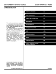
QUICK REFERENCE INDEX
GENERAL INFORMATION
SECTION
This service manual has been prepared
to provide SUBARU service personnel
with the necessary information and data
for the correct maintenance and repair
of SUBARU vehicles.
This manual includes the procedures
for maintenance, disassembling, reassembling, inspection and adjustment of
components and diagnostics for guidance of experienced mechanics.
Please peruse and utilize this manual
fully to ensure complete repair work for
satisfying our customers by keeping
their vehicle in optimum condition.
When replacement of parts during
repair work is needed, be sure to use
SUBARU genuine parts.
FOREWORD
FW
HOW TO USE THIS MANUALS
HU
SPECIFICATIONS
SPC
PRECAUTION
PC
NOTE
NT
IDENTIFICATION
ID
RECOMMENDED MATERIALS
RM
PRE-DELIVERY INSPECTION
PI
PERIODIC MAINTENANCE SERVICES
PM
All information, illustration and specifications contained in this manual are
based on the latest product information
available at the time of publication
approval.
FUJI HEAVY INDUSTRIES LTD.
G4400BE
FOREWORD
1.
FW
Page
Foreword ....................................................................................................2
Foreword
FOREWORD
1. Foreword
A: FOREWORD
These manuals are used when performing maintenance, repair or diagnosis of Subaru BRZ.
Applicable model:
2013 MY ZC*****
The manuals contain the latest information at the
time of publication. Changes in the specifications,
methods, etc. may be made without notice.
FW-2
HOW TO USE THIS MANUALS
1.
HU
Page
How to Use This Manuals ..........................................................................2
How to Use This Manuals
HOW TO USE THIS MANUALS
1. How to Use This Manuals
A: HOW TO USE THIS MANUALS
1. STRUCTURE
Each section consists of SCT that are broken down
into SC that are divided into sections for each component. The specification, maintenance and other
information for the components are included, and
the diagnostic information has also been added
where necessary.
2. CONTENTS
The first page has an index with tabs.
HU-2
How to Use This Manuals
HOW TO USE THIS MANUALS
3. COMPONENT
Illustrations are provided for each component. The information necessary for repair work (tightening torque,
grease up points, etc.) is described on these illustrations. Information is described using symbol.
To order parts, refer to parts catalogue.
Example:
(7)
(5)
T10
T5
(5)
T6
(8)
(20)
(1)
T1
T3
(4)
(2)
T8
T2
(3) (6)
T3
(21)
T2
T3
T2
(1)
T3
(2)
T4
(4)
(4)
(3)
(10)
(11)
(11)
(10)
(9)
(12) (22)
(23)
(16)
(14)
(9)
(6)
T3
(18)
T1
(13)
(15)
T2
(17)
(19)
T6
(4)
(3)
(7)
T4
(10)
(4)
(15)
T2
T11
(22)
T6
T5
(3)
(12)
(35)
T4
(8)
(10)
(23)
(14)
T2
T5
(27)
T2
(34)
T3
(26)
(24)
(25)
T7
(24)
(25)
(13)
(36)
(31)
(30)
T2
T5
(29)
(10)
(17)
(16)
(37)
(32)
(28)
(18)
T3
(33)
T4
T1
: Selective part
: Replacement part
T1
(21)
: Sealing point
: Should be lubricated with oil.
(20)
T9
: Should be lubricated with grease.
(19)
T1
,
T2
....
: Tightening torque
HU-00017
Courtesy of FT86CLUB.com
HU-3
How to Use This Manuals
HOW TO USE THIS MANUALS
4. DEFINITIONS OF “NOTE”, “CAUTION”, AND “WARNING”
• NOTE:
The supplementary explanation to facilitate the work is described.
• CAUTION:
The matter that must not be performed because failure to follow the description causes damage to the vehicle or parts, and the one to which attention should be particularly paid during the work are described.
• WARNING:
The matter that may seriously damage the worker or others and the one results in failures or accidents in
case of failure to follow the description are described.
5. SPECIFICATIONS
If necessary, specifications are also included.
6. INSPECTION
Inspections to be carried out before and after maintenance are included.
HU-4
How to Use This Manuals
HOW TO USE THIS MANUALS
7. MAINTENANCE
• Maintenance instructions for serviceable parts describe work area and detailed step with illustration. It also
describes the use of special tool, tightening torque, caution for each procedure.
• If many serviceable parts are included in one service procedure, appropriate reference is provided for each
parts.
Example:
15.Main Shaft
(A)
A: REMOVAL
(B)
1) Remove the manual transmission assembly
from vehicle. <Ref. to MT-33, REMOVAL, Manual
Transmission Assembly.>
(C)
11) Tighten the lock nuts to the specified torque using ST1 and ST2.
NOTE:
Secure the lock nuts in two places after tightening.
ST1 498937000
TRANSMISSION HOLDER
ST2 499987003
SOCKET WRENCH (35)
(E)
Tightening torque:
120 N m (12.2 kgf-m, 88.5 ft-lb)
(D)
(F)
(G)
(H)
ST2
ST1
HU-00041
(A)
(B)
(C)
Component
Process
Reference
(D)
(E)
(F)
Cautions
Tool number of special tool
Name of special tool
(G)
(H)
8. DIAGNOSIS
Tables showing a step-by-step process make it easy to conduct diagnosis.
HU-5
Tightening torque
Illustration
How to Use This Manuals
HOW TO USE THIS MANUALS
9. SI UNITS
Measurements in these manuals are according to the SI units. Metric and yard/pound measurements are
also included.
Example:
Tightening torque:
45 N·m (4.6 kgf-m, 33.2 ft-lb)
List of SI unit
Item
Force
Mass (Weight)
Capacity
Torque
Rotating speed
SI units
N (Newton)
kg, g
L, mL or cm3
N·m
rpm
Pressure
kPa (Kilopascal)
Power
Calorie
Fuel consumption rate
W
W·h
g/kW·h
Conventional unit
kgf
kg, g
L or cc
kgf-m, kgf-cm
rpm
kgf/cm2
mmHg
PS
cal
g/PS·h
Remarks
1 kgf = 9.807 N
1 cc = 1 cm3 = 1 mL
1 kgf-m = 9.807 N·m
1 kgf/cm2 = 98.07 kPa
1 mmHg = 0.1333 kPa
1 PS = 0.7355 kW
1 kcal = 1.163 W·h
1 g/PS·h = 1.3596 g/kW·h
The figure used in these manuals are described in the SI units and conventional units are described in (
HU-6
).
How to Use This Manuals
HOW TO USE THIS MANUALS
10.EXPLANATION OF TERMINOLOGY
List
2ndr
AAI
AAR
A/B
ABS
A/C
AC
ACC
A/F
ALT
APS
ASSY
AT
ATF
AUX
AVCS
AWD
BATT
BCM
BJ
CAN
CD
CD-R/RW
COMPL
CPC
CPU
DCCD
DOHC
DOJ
DTC
DVD
EBD
EBJ
ECM
EDJ
E/G
EGI
EGR
ELR
ETC
EX
F/B
FL
Ft
FWD
GPS
HI
HID
H/L
H/U
HVAC
I/F
IG
IN
INT
I/O
IR
ISC
LAN
LCD
LED
LH
LHD
LSD
M/B
MD
MID
MFI
MP-T
MT
NA
NC
NO
OBD
OP
PC
PCD
PCV
PID
Pr
P/S
PTJ
P/W
RAM
RH
RHD
ROM
rpm
Rr
SDI
SI
SOHC
SRS
SSM
ST
STD
SW
Secondary
Air Assist Injection
Angular Adjusted Roller
Airbag
Anti-lock Brake System
Air Conditioner
Angular Contact
Accessory
Air Fuel Ratio
Generator
Accessory Power Supply Socket
Assembly
Automatic Transmission
Automatic Transmission Fluid
Auxiliary Storage Unit (External storage)
Active Valve Control System
All Wheel Drive
Battery
Brake Control Module
Bell Joint
Controller Area Network
Compact Disc
CD Recordable/Rewritable
Complete
Canister Purge Control Solenoid Valve
Central Processing Unit
Driver’s Control Center Differential
Double Overhead Camshaft
Double Offset Joint
Diagnosis Trouble Code
Digital Versatile Disc or Digital Video Disc
Electronic Brake Distribution
High-efficiency Compact Ball Fixed Joint
Engine Control Module
High-efficiency Compact Double Offset
Joint
Engine
Electronic Gasoline Injection
Exhaust Gas Recirculation
Emergency Locking Retractor
Electronic Throttle Control
Exhaust
Fuse & Joint Box
Fusible Link
Front
Front Wheel Drive
Global Positioning System
High
High-Intensity Discharge
HU-7
Headlight
Hydraulic Unit
Heater, Ventilator and Air Conditioner
Interface
Ignition
Intake
Intermittent
Input / Output
Infrared Ray
Idle Speed Control
Local Area Network
Liquid Crystal Display
Light Emitting Diode
LH (Left Hand)
Left Hand Drive
Limited Slip Differential
Main Fuse & Relay Box
Mini Disc
Multi Information Display
Multi-Point Fuel Injection
Multi-Plate Transfer
Manual Transmission
Natural Aspiration
Normal Close (Relay)
Normal Open (Relay)
On-Board Diagnosis
Option Parts
Personal Computer
Pitch Circle Diameter
Positive Crankcase Ventilation
Parameter Identification
Primary
Power Steering
Pillow Tripod Joint
Power Window
Random Access Memory
RH (Right Hand)
Right Hand Drive
Read Only Memory
Revolution Per Minute
Rear
Subaru Diagnostic Interface
Subaru Intelligent
Single Overhead Camshaft
Supplemental Restraint System
Subaru Select Monitor
Special Tool
Standard
Switch
How to Use This Manuals
HOW TO USE THIS MANUALS
T/B
TCS
TCM
TGV
T/M
TPMS
UJ
UV
VDC
V.I.N.
ViS-C
VSV
VTD
W/H
Turbocharger
Traction Control System
Transmission Control Module
Tumble Generator Valve
Transmission
Tire Pressure Monitoring System
Universal Joint
Ultraviolet
Vehicle Dynamics Control
Vehicle Identification Number
Viscous Coupling
Vacuum Switching Valve
Variable Torque Distribution
Wiring Harness
Courtesy of FT86CLUB.com
HU-8
SPECIFICATIONS
1.
SPC
Page
BRZ ............................................................................................................2
BRZ
SPECIFICATIONS
1. BRZ
A: DIMENSION
Model
Overall length
Overall width
mm (in)
mm (in)
Overall height
mm (in)
Compartment
Length
Width
Height
mm (in)
mm (in)
mm (in)
mm (in)
mm (in)
mm (in)
mm (in)
Wheelbase
Front wheel
Rear wheel
Minimum road clearance
Tread
*1:
*2:
2.0 L non-turbo
4,235 (166.7)
1,775 (69.9)
1,430 (56.3)*1
1,425 (56.1)*2
1,615 (63.6)
1,490 (58.7)
1,060 (41.7)
2,570 (101.2)
1,520 (59.8)
1,540 (60.6)
125 (4.9)
U4 model
Canada model
B: ENGINE
Model
Engine type
Valve arrangement
Bore × stroke
Displacement
Compression ratio
Ignition order
Idle speed at Park or
Neutral position
mm (in)
cm3 (cu in)
MT
AT
rpm
rpm
HP (kW)/rpm
ft-lb (N·m)/rpm
Maximum output
Maximum torque
2.0 L non-turbo
Horizontally opposed, liquid cooled, 4-cylinder,
4-stroke gasoline engine
Overhead camshaft type
86.0 × 86.0 (3.39 × 3.39)
1,998 (121.92)
12.5
1—3—2—4
650 100
700 100
200 (149)/7,000
151 (205)/6,400 — 6,600
C: ELECTRICAL
Model
Ignition timing/Idle
speed
Spark plug
Generator
Battery
MT
AT
DENSO
BTDC/rpm
BTDC/rpm
Type and capacity (5HR)
Courtesy of FT86CLUB.com
SPC-2
2.0 L non-turbo
12° 10°/650
12° 10°/700
ZXE27HBR8
12 V — 130 A
MT/AT: 12 V — 48 AH (55D23R)
BRZ
SPECIFICATIONS
D: TRANSMISSION
1. MT
Model
Transmission
Clutch type
Gear ratio
Reduction gear (Rear) Final reduction
2.0 L non-turbo
6MT
DSPD
3.626
2.188
1.541
1.213
1.000
0.767
3.437
Hypoid
4.100
1st
2nd
3rd
4th
5th
6th
Rev.
Type of gear
Gear ratio
6MT: 6-forward speeds and 1-reverse with synchromesh
DSPD: Dry Single Plate Diaphragm
2. AT
Model
Transmission
Clutch type
Gear ratio
Reduction gear (Rear) Final reduction
2.0 L non-turbo
6AT
TCC
3.538
2.060
1.404
1.000
0.713
0.582
3.168
Hypoid
4.100
1st
2nd
3rd
4th
5th
6th
Rev.
Type of gear
Gear ratio
6AT: Electronically controlled fully-automatic, 6-forward speeds and 1-reverse
TCC: Torque Converter Clutch
E: STEERING
Model
Type
Turns, lock to lock
Minimum turning radius
m (ft)
2.0 L non-turbo
Rack & pinion type
Electric power steering
2.4
5.4 (17.7)
F: SUSPENSION
Front
Rear
Macpherson strut type independent suspension
Double-wishbone type independent suspension
Courtesy of FT86CLUB.com
SPC-3
BRZ
SPECIFICATIONS
G: BRAKE
Service brake system
Front
Rear
Parking brake
Dual circuit hydraulic with vacuum suspended power unit
Ventilated disc brake
Solid disc brake
Ventilated disc brake
Mechanical on rear brakes
H: TIRE
Rim size
Tire size
Type
I:
16 × 6.5J, 16 × 6.5JJ
17 × 7J
205/55R16
215/45R17
Tubeless, Steel belted radial
CAPACITY
Model
Transmission
Fuel tank
Engine oil
2.0 L non-turbo
MT
L (US gal, Imp gal)
When replacing engine oil and oil filter
Filling amount of engine oil
L (US qt, Imp qt) When replacing engine oil only
Total capacity
L (US qt, Imp qt)
(at overhaul)
Transmission oil
L (US qt, Imp qt)
ATF
L (US qt, Imp qt)
Rear differential gear oil
L (US qt, Imp qt)
Engine coolant
L (US qt, Imp qt)
Courtesy of FT86CLUB.com
SPC-4
AT
50 (13.2, 11.0)
5.4 (5.7, 4.8)
5.2 (5.5, 4.6)
6.3 (6.7, 5.5)
2.2
(2.3, 1.9)
—
7.5
(7.9, 6.6)
1.1 — 1.2 (1.2, 1.0 — 1.3, 1.1)
7.2
7.5
(7.6, 6.3)
(7.9, 6.6)
—
BRZ
SPECIFICATIONS
J: WEIGHT
2 door
R
Model
Transmission
MT
OP code
Total
Curb weight
(C.W.)
Front
Rear
Gross vehicle weight (G.V.W.)
Gross axle
weight
(G.A.W.)
Option
AT
C0
Front
Rear
A package
LSD
Leather package
Spare tire
HID headlight
Leather seat
17-inch summer tire
Manual A/C
Auto A/C
kg
(lb)
kg
(lb)
kg
(lb)
kg
(lb)
kg
(lb)
kg
(lb)
U4
C0
U4
NJ
NW
NJ
NW
NJ
NW
NJ
NW
1,253
(2,762)
691
(1,523)
562
(1,239)
1,670
(3,682)
876
(1,931)
943
(2,079)
1,255
(2,767)
691
(1,523)
564
(1,243)
1,670
(3,682)
876
(1,931)
943
(2,079)
1,253
(2,762)
691
(1,523)
562
(1,239)
1,670
(3,682)
876
(1,931)
943
(2,079)
1,255
(2,767)
691
(1,523)
564
(1,243)
1,670
(3,682)
876
(1,931)
943
(2,079)
1,274
(2,809)
710
(1,565)
564
(1,243)
1,700
(3,748)
876
(1,931)
943
(2,079)
1,276
(2,813)
710
(1,565)
566
(1,248)
1,700
(3,748)
876
(1,931)
943
(2,079)
1,274
(2,809)
710
(1,565)
564
(1,243)
1,700
(3,748)
876
(1,931)
943
(2,079)
1,276
(2,813)
710
(1,565)
566
(1,248)
1,700
(3,748)
876
(1,931)
943
(2,079)
—
—
—
—
—
—
—
—
—
—
—
—
—
—
—
—
—
—
—
—
Courtesy of FT86CLUB.com
SPC-5
BRZ
SPECIFICATIONS
2 door
S
Model
Transmission
MT
OP code
Total
Curb weight
(C.W.)
Front
Rear
Gross vehicle weight (G.V.W.)
Gross axle
weight
(G.A.W.)
Option
Front
Rear
A package
LSD
Leather package
Spare tire
HID headlight
Leather seat
17-inch summer tire
Manual A/C
Auto A/C
kg
(lb)
kg
(lb)
kg
(lb)
kg
(lb)
kg
(lb)
kg
(lb)
AT
C0
NG
U4
NG
C0
NG
U4
NG
1,259
(2,776)
693
(1,528)
566
(1,248)
1,670
(3,682)
876
(1,931)
943
(2,079)
1,259
(2,776)
693
(1,528)
566
(1,248)
1,670
(3,682)
876
(1,931)
943
(2,079)
1,280
(2,822)
712
(1,570)
568
(1,252)
1,700
(3,748)
876
(1,931)
943
(2,079)
1,280
(2,822)
712
(1,570)
568
(1,252)
1,700
(3,748)
876
(1,931)
943
(2,079)
—
—
—
—
Courtesy of FT86CLUB.com
SPC-6
PRECAUTION
1.
PC
Page
Precaution ..................................................................................................2
Precaution
PRECAUTION
1. Precaution
6. AIRBAG MODULE AND SEAT BELT
PRETENSIONER DISPOSAL
A: CAUTION
Please clearly understand and adhere to the following general precautions for environmental protection and to avoid minor or serious injury to the
person doing the work or people in the area.
To prevent bodily injury from unexpected airbag
deployment, do not dispose the airbag modules or
seat belt pretensioner in the same way as other
waste. Follow all government regulations concerning disposal of refuse.
1. VEHICLE STABILITY CONTROL (VSC)
7. AIRBAG MODULE
Handle the VSC as a total system. Do not disassemble or attempt to repair individual parts. Follow
the directions in this manual when performing
maintenance on the VSCCM&H/U. When parts other than those specified are disassembled, it is possible that the VSC system will not operate when
needed or cause it to operate incorrectly and result
in injury.
Adhere to the following when handing and storing
the airbag module to prevent bodily injury from unexpected deployment:
• Do not hold the harnesses or connectors to carry
the module.
• Do not face the bag in the direction that it opens
towards yourself or other people.
• Do not face the bag in the direction that it opens
towards the floor or walls.
2. BRAKE FLUID
If brake fluid gets in your eyes or on your skin, do
the following:
• Wash eyes and seek immediate medical attention.
• Wash your skin with soap and then rinse thoroughly with water.
3. RADIATOR FAN
The radiator fan may rotate without warning, even
when the engine is not ON. Do not place your hand,
cloth, tools or other items near the fan at any time.
4. ROAD TEST
Always conduct road tests in accordance with traffic rules and regulations to avoid bodily injury and
interrupting traffic.
5. AIRBAG
To prevent bodily injury from unexpected deployment of airbags and unnecessary maintenance, follow the instructions in this manual when performing
maintenance on the airbag components or nearby,
around front of the vehicle (radiator panel, front
wheel apron, front side frame, bumper, hood, front
fender), around side of the vehicle (doors, center
pillar, rear fender, side sill, rear wheel apron),
around rear of the vehicle (rear seat cushion, rear
floor, rear crossmember) and the airbag wiring harnesses or nearby.
To prevent unexpected deployment, turn the ignition switch to OFF and disconnect the ground cable
from battery, then wait at least 60 seconds before
starting work.
8. AIRBAG SPECIAL TOOL
To prevent unexpected deployment, only use special tools.
9. WINDOW
Always wear safety glasses when working around
any glass to prevent glass fragments from damaging your eyes.
10.WINDOW ADHESIVE
Always use the recommended or equivalent adhesive when attaching glass to prevent it from falling
off, resulting in accidents and injury.
11.OIL
When handling oil, adhere to the following to prevent unexpected accident.
• Prepare a container and cloth to prevent scattering of oil when performing work where oil can be
spilled. If the oil spills, wipe it off immediately to prevent from penetrating into floor or flowing out for
environmental protection.
• Follow all government and local regulations concerning disposal of refuse when disposing.
PC-2
Precaution
PRECAUTION
12.FUEL
When handling and storing fuel, adhere to the following to prevent from unexpected accident.
• Be careful with fire.
• Prepare a container and cloth to prevent scattering of fuels when performing work where fuels can
be spilled. If the oil spills, wipe it off immediately to
prevent from penetrating into floor or flowing out for
environmental protection.
• Follow all government and local regulations concerning disposal of refuse when disposing.
13.ENGINE COOLANT
When handling engine coolant, adhere to the following to prevent from unexpected accident.
• Never remove the radiator cap since engine
coolant may blow out when it is hot.
• Prepare a container and cloth to prevent scattering of engine coolant when performing work where
engine coolant can be spilled. If the oil spills, wipe it
off immediately to prevent from penetrating into
floor or flowing out for environmental protection.
• Follow all government and local regulations concerning disposal of refuse when disposing.
15.REMOVAL AND INSTALLATION OPERATION OF HOSES, ETC.
1. Before the removal and installation operation
of hoses, etc.
• If you keep using the damaged or deformed
hose, it results bleeds or leakage of the fat adheres
or disconnection of the hose. Be careful not to spill
fat adheres on exhaust pipes, etc. during maintenance to prevent emitting smoke or causing fires.
• Perform the operation with the hose removed. If
the operation is performed without removing the
hose, it may damage inner surface of the hose.
2. Removal and installation operation of hoses,
etc. during the inspection
• Follow the instructions below when removing hose.
• Do not use a pointed hose remover (hose
plucker) when using a general hose remover. It
may damage the pipe surface or the hose.
14.AIR CONDITIONER REFRIGERANT
In order to prevent from global warming, avoid releasing air conditioner refrigerant into the atmosphere. Using a refrigerant recovery system,
discharge and reuse it.
NG
N
G
OK
K
(1)
(1)
PC-00065
(1) Hose remover
• When draining hose using pliers, be sure to
cover the hose with cloth and rotate the hose
slightly to extract straight.
PC-3
Precaution
PRECAUTION
• If you keep using the hose, perform the inspection below and replace the hose with a new
part if faulty.
• Replace the hose with a new part if it rides
over the stay or the top of spool.
(1)
• Follow the instructions below during installation.
• Check carefully for assembling position.
• Never use lubricants.
• Insert the hose to the specified position (stopper or spool) securely. (The spool stopper is the
space from the top of the spool to the base.)
(2)
(1)
PC-00071
(1) Hose rides over the stay
PC-00074
(1)
(1)
PC-00070
PC-00077
(1) Hose rides over the top of spool
• Check if the surface and the inner surface of
the hose are damaged, cracked, bend, hardened, softened, swelled, peeled or deformed
due to the adherence or the entry of the foreign
matter by bending the hose. Replace with the
new part if faulty.
PC-4
Precaution
PRECAUTION
• For hose clips and hose clamps, perform the
inspection below and replace them with a new
part if faulty.
• Check for deformation, rust, damage or foreign matters.
• For hose clip, check if it works and has clamping force.
• For hose clamp, check if it can tighten screw,
not ovalized or the screw is not damaged.
• For hose pipes, perform the inspection below
and replace with a new part if faulty.
Check if the pipe is not damaged, rusted, peeled
(peeled plates included), covered with foreign
matter, bent, compressed or cracked.
• For the parts below, replaces with a new part
when the hose is removed or the installation
position is changed.
ATF cooler hose, fuel hose (delivery)
(A)
(B)
PC-00080
(1) Push against the spool. (Insert the hose and
prevent it from becoming wrinkled.)
(2) Tighten the hose outwards and apply force thoroughly.
(A) Correct position (Spool base)
(B) Correct position (Spool top)
• Check if the position, direction and hose layout of the hose clamp are correct. (Check if the
position, direction, length and the gap around
are correct, or if it is different from the condition
before the work)
• After the installation, check that the hose is installed securely and there is no leakage. (Check
if it is fixed securely with the clamp)
PC-5
Precaution
PRECAUTION
16.HANDLING PRECAUTIONS FOR SILICON-CONTAINING SPRAY
When a silicone contained in the lubricant, rust inhibitor or glazing agent adheres to the electrical contact of
the relay or switch, nonconducting silica dioxide (SiO2) film will be formed, which may lead to poor continuity.
Therefore, the following precautions must be observed when using the silicon-containing spray.
• Never spray directly to the electrical equipment.
• When using the spray close to the electrical equipment, always put the cover on it. Be sure to put the cover
on the electrical equipment especially when using the spray to the locations shown in the figure below and
their surrounding areas.
(1)
(3)
(5)
(5)
(2)
(4)
PC-00079
(1)
(2)
Audio, heater control switch
Shift/select lever switch, parking
switch
(3)
(4)
Combination switch
Stop light switch, brake switch,
clutch switch, clutch start switch
(5)
Power window switch
• If the residual silicon remains in the vicinity of the electrical equipment after the spray has been used, the
vaporized silicon stands around the electrical equipment and it may adhere to electrical contact. After using
the spray, be sure to wipe the silicon off with a cloth.
• Even when using the spray to the place away from the electrical equipment, the droplet of the spray may
be splashed to the periphery. Use as small amount of spray as possible, and take care not to splash the silicon to the periphery.
NOTE:
The “silicon” used in this section refers to “silicone”, that is, silicon polymer.
PC-6
NOTE
NT
1.
Page
Note ............................................................................................................2
Note
NOTE
1. Note
A: BASIC REPAIR HINT
This section describes basic points that the service operator must understand before performing the service
operation.
1. APPEARANCE
• Always wear clean work clothing.
• Wear a cap and protective shoes.
2. PROTECTION OF VEHICLE UNDER MAINTENANCE AND PREPARATION OF TOOLS/
EQUIPMENT
• Before work, cover the vehicle body. (Ex. grille cover, fender cover, seat cover and floor mat cover)
• Before performing the service operation, prepare tools, equipment, container box, grease and cloth etc.
(1)
(2)
(3)
(4)
(5)
(6)
NT-00445
(1)
(2)
Fender cover
Tools/equipment case
(3)
(4)
Tray
Oil
(5)
(6)
Container box
Cloth
3. SAFETY
4. SERVICE OPERATION
• Before work, set the wheel stoppers to secure
the vehicle.
• When performing work by multiple workers, call
to each other to make sure that service operation is
performed safely.
• Before starting engine, ventilate the room.
• When performing the service operation of hightemperature parts like muffler, rotating parts like
fan and other movable parts, be careful not to get
burned or injured.
• For the jack-up and lift up, set the tool to the
proper location to support the vehicle correctly. And
use the safety device properly when lifting up.
• By identifying the vehicle problems thoroughly
before work, service operation will be performed effectively.
• Before removing parts, confirm the installation
condition or the damage of the parts.
• To reinstall parts properly, leave a note of the
condition before work as necessary.
• For a part which needs positioning, take appropriate action such as putting alignment marks.
• For a removed part, clean it as necessary and
check for damage and defect before installation.
NT-2
Note
NOTE
5. REMOVED PART
• A removed part must be organized to avoid mixing up with similar parts. When same parts are used in multiple locations, such as pistons in engine, manage the parts by using labels with cylinder No. so that the parts
are not installed to the wrong location.
• Always replace nonreusable parts such as gasket and O-ring with new parts.
• After work, have a customer confirm the replaced part.
6. WHEN REMOVING BATTERY
• To prevent damaging the retainer & molding assembly, completely close the front door glass on driver's
and passenger's sides before removing the battery.
• When removing battery, power supply is cut off and the information stored in the computer memory is volatilized. Therefore, setting information of some device is initialized to the factory default. The device and
functions initialized by removing battery are as follows.
No.
1
2
Item
Clock
Temperature setting of fully automatic air conditioner (Setting made by customer)
3
Power window system
4
Steering lock system (Models with keyless access)
5
Electronic throttle system
6
Engine control system
7
Past trouble history (memory code)
Procedures for connecting the battery
Set to the clock to the current time.
Restore to the setting before removing battery.
Perform initialization of automatic full open/close of driver's
window (power window system).
If the engine does not start, initialize the steering lock system.
Turn the ignition switch to ON, and wait 10 seconds before
starting the engine.
With no electronic loads applied, allow the engine to idle
until it is completely warmed up (until the radiator fan is activated two times or more).
—
7. ADJUSTMENT SERVICE PROCEDURES PERFORMED BEFORE DELIVERY TO CUSTOMER
Perform the following procedures before delivering the vehicle to the customer according to maintenance
performed and parts replaced.
No.
Item
Check points
Adjustment procedures
Adjustment procedures also performed when replacing parts
1
Each device location
• Steering
• Room mirror
• Door mirror
• Seat
• Air conditioning vent grille
Are all devices in the
same positions as when
the vehicle was received
from the customer?
Adjust all devices to be in
the same positions as
when the vehicle was
received from the customer.
During device removal/installation
procedures
• Motor, instrument panel, steering column and similar parts
• Room mirror, roof trim and similar parts
• Door mirrors, door panels and
similar parts
• Seats, floor carpet, parking
brake lever and similar parts
• Vent grilles, instrument panel,
console box and similar parts
2
Position of all switches
• Wipers, lights (AUTO or
OFF)
• Illumination control
• Room light
• Seat heater and similar
parts
Are all switches in the
same positions as when
the vehicle was received
from the customer?
Return all switches to the
same positions as when
the vehicle was received
from the customer.
During switch removal/installation procedures
Antenna position
Is the antenna in the same
positions as when the
vehicle was received from
the customer?
Adjust antenna position.
During antenna removal/installation procedures and car wash
3
NT-3
Note
NOTE
B: NOTE
5. BACKUP/POWER SUPPLY FUSE
This is the information that can improve the efficiency of maintenance and assure the sound work.
The 30A fuse is moved from position (A) to (B) as
shown in the figure below to prevent battery consumption when vehicles are delivered. Remove the
fuse from (B) and install in (A) as shown in the figure below. Removing the fuse from (B) deactivates
control during shipping (delivery mode).
1. CAR WASH
• Perform procedures in a clean location and take
measures to protect from dust.
• Before disassembly, clean all parts except for
assembly parts with steam etc. When steam cleaning, use vinyl tape or similar material to plug up
parts such as the air breather, oil level gauge and
connectors so as to prevent steam from getting inside such parts.
• Use new white kerosene or similar liquid as the
cleaning solution.
• Never wash rubber parts, such as o-rings, gaskets and oil seals, using cleaning solution.
2. FASTENERS NOTICE
Tighten the bolts and nuts to the specified torque.
Do not apply paint, lubricant, rust retardant or other
substance to the surface around bolts, nuts, etc. It
may cause troubles with tightening to the specified
torque and result in looseness and other problems
of bolts and nuts.
3. STATIC ELECTRICITY DAMAGE
Do not touch the control modules, connectors, logic
boards and other such parts when there is a risk of
static electricity. Always use a static electricity prevention cord or touch grounded metal for the elimination of static electricity before conducting work.
4. BATTERY
When removing the battery terminal, always be
sure to turn the ignition switch to OFF and disconnect the battery ground terminal first.
For models equipped with the keyless access with
push button start system, turn off all power supply
(indicator of the push button ignition switch goes
off) before disconnecting the battery ground terminal.
(A)
(B)
NT-00457
6. IMMOBILIZER RELATED PART
Do not replace parts which have an immobilizer ID
(all ignition keys, combination meter (except for
Canada), body integrated unit, ECM and SCM (for
Canada), access key, keyless access CM, steering
lock CM and ID code box (for Canada) with parts
from other vehicles.
7. SERVICE PARTS
Use genuine parts for maximum performance and
maintenance when conducting repairs. Subaru/FHI
will not be responsible for poor performance resulting from the use of parts except for genuine parts.
8. PROTECTING VEHICLE UNDER MAINTENANCE
Make sure to attach the fender cover, seat covers,
etc. before work.
9. ENSURING SECURITY DURING WORK
When working in a group of two or more, perform
the work with calling each other to ensure mutual
safety.
NT-4
Note
NOTE
10.LIFT AND JACK
When using a lift or shop jack to raise a vehicle or
using rigid rack to support a vehicle, always follow
instructions concerning jack-up points and weight
limits to prevent the vehicle from falling, which
could result in injury. Be especially careful that the
vehicle is balanced before raising it. Be sure to set
the wheel stoppers when jacking-up only the front
or rear side of the vehicle.
CAUTION:
Select the lift attachment so that the side sill
does not contact the lift arm.
NOTE:
• When using a lift, follow its operation manual.
• When the side sill cover contacts the lift arm, use
a lift attachment.
• Do not work or leave unattended while the vehicle is supported with jack, support it with rigid
racks.
• Be sure to use the rigid racks with rubber attached to cradle to support the vehicle.
• When using a lift, use an attachment or something similar.
• When using a plate lift, use a rubber attachment.
Place the attachment to the specified position of
the vehicle, by adjusting front/rear and left/right
sides accordingly.
(A)
(C)
(B)
NT-00070
(A) 80 mm (3.1 in) or more
(B) 80 — 100 mm (3.15 — 3.94 in)
(C) 120 — 200 mm (4.72 — 7.87 in)
• Align the cushion rubber center part of plate lift
with the center part of rubber attachment.
• Do not use the plate lift whose attachment does
not reach the supporting locations.
NT-5
Note
NOTE
• Support locations
(1)
(1)
NT-00467
(1)
Jack-up point
• Pantograph jack
CAUTION:
When storing the jack holder after use, store with the jack handle mount of the jack facing the inside
of the trunk.
(1)
(1)
NT-00459
(1)
Jack-up point
Courtesy of FT86CLUB.com
NT-6
Note
NOTE
• Lift
NT-00271
CAUTION:
For models with side under skirt, use a spacer or an attachment to lift up the vehicle securely at jack
up point, without contact of side under skirt and lift.
• Rigid rack
(A)
NT-00242
(A)
Attachment
NT-7
Note
NOTE
• Plate lift
(1)
(1)
(2)
NT-00452
(1)
Jack-up point
(2)
Attachment
• Jack-up point (When using a garage jack)
(A)
(1)
(B)
(2)
NT-00447
(A)
(1)
Front
Frame
(B)
(2)
Rear
Rear differential
CAUTION:
If jacking up the front side of the vehicle, make sure that the jack is attached at the center of the jackup plate not at the sides.
NT-8
Note
NOTE
11.TIE-DOWNS
Tie-downs are used when transporting vehicles and when using the chassis dynamo. Attach tie-down only
to the specified locations on the vehicle.
• Tie-down location
(2)
(1)
NT-00453
(1)
Hook for tie-down
(2)
Tie-down hole
• Chain direction at tie-down condition
CAUTION:
• Pull the front and rear of the vehicle in the opposite direction, and pull the left and right of the vehicle in the same direction.
• Patterns except for the followings (recommended) are not allowed.
Recommended
Tie-down direction
NT-00214
NT-9
Note
NOTE
• Tie-down range
For ground transportation
20
20
˚
˚
20
Courtesy of FT86CLUB.com
20
˚
˚
20
˚
20˚
20
˚
20˚
20˚
20
˚
20
˚
20
20
˚
20˚
20˚
20˚
˚
CAUTION:
To tie down the vehicle from the vehicle interior, hook the hooks of the tie-down chain on the rear tiedown holes from the vehicle interior. When the vehicle is tied down from vehicle outside, hook the
hooks of tie-down chain on the rear tie-down hooks from vehicle outside.
(B)
(A)
45˚
˚
45˚
45
˚
45
:(C)
(A)
Front tie-down hook
NT-00462
(B)
Rear tie-down hole
NT-10
(C)
Chain pulling range at tie-down
condition
Note
NOTE
For sea transportation
CAUTION:
The eye bolts are exclusively used for towing and sea transportation tie-down, and do not use them
for ground and freight transportation.
(F)
70
43˚
(E)
˚
˚
70
70˚
43˚
70˚
(B)
(A)
(D)
˚
70
:(C)
NT-00463
(A)
Front tie-down hook
(C)
(B)
Eye bolt
(D)
Chain pulling range at tie-down
condition
400 mm (15.7 in)
NT-11
(E)
1,500 mm (59.1 in)
(F)
1,217 mm (47.9 in)
Note
NOTE
• Vehicle sinking volume at tie-down condition
CAUTION:
The vehicle sinking volume at tie-down condition should be less than 50 mm (1.97 in) and make sure
to fix the vehicle securely.
Check to see if the tensions of chains or belts at tie-down condition are appropriate in the following
procedures.
1) Before tie-down, measure the distance between the highest tire point and highest arch point at the center
of wheel.
2) After tie-down, measure the distance between the highest tire point and highest arch point at the center of
wheel.
3) If the distance (A) between the measured value of 1) and 2) above, is less than 50 mm (1.97 in), it is judged
as OK. If the distance is 50 mm (1.97 in) or more, it is judged as NG because the tension is too high.
(B)
(C)
(B)
(C)
(A)
(A)
NT-00456
(B)
Arch position before tie-down
(C)
Arch position after tie-down
• Notes for the use of tie-down hook
When the vehicle is tied down from vehicle inside, hook the hooks of tie-down chain from vehicle inside, and
when the vehicle is tied down from vehicle outside, hook the hooks of tie-down chain from vehicle outside.
For front tie-down hook, use S hook and J hook, and for rear tie-down hole, use S hook, J hook and T hook.
T hook can be used only for rear tie-down hole.
Courtesy of FT86CLUB.com
NT-12
Note
NOTE
12.TOWING
Avoid towing vehicles except when the vehicle cannot be driven. For AT models, use a loader instead of towing. When towing other vehicles, pay attention to the following to prevent hook or vehicle damage resulting
from excessive weight.
• Do not tow other vehicles with a front tie-down hook.
• Make sure the vehicle towing is heavier than the vehicle being towed.
• Front
Remove the hook cover, and install the towing hook (eye bolt).
(A)
(B)
NT-00448
(A)
Hook cover
(B)
Towing hook (eyebolt)
• Rear
Remove the hook cover, and install the towing hook (eye bolt).
(A)
(B)
NT-00449
(A)
Hook cover
(B)
Towing hook (eyebolt)
NT-13
Note
NOTE
• Precautions
Towing
Lifting up four wheels (On a trailer)
Precautions
Use car carrier truck when the chassis or drivetrain of a vehicle has been damaged in an accident.
NT-00023
Rope
• Check if both front and rear wheels are rotated normally.
• Driving conditions: Driving speed 30 km/h (19 MPH) or less
Allow driving distance 30 km (19 miles) or less
NT-00024
Raising the front wheels
NT-00025
Lifting up the front wheels
• Prohibited, due to damage on bumper, front grille, etc.
• Do not raise the vehicle with bumper.
NT-00026
Marked
: OK, Marked
: Prohibited, Marked
: Conditionally OK.
NT-14
MT
AT
Note
NOTE
CAUTION:
• Place the shift lever in “N” position during towing.
• Do not lift up the rear wheels to avoid unsteady rotation.
• Turn the ignition key to “ACC”, then check the steering wheel moves freely. (Models without the
keyless access with push button start system)
• Turn the ignition switch to “ACC” or “ON” position, and check that the steering wheel moves
freely. (Models equipped with the keyless access with push button start system)
• Release the parking brake to avoid tire dragging.
• Since the power steering does not work, be careful for the heavy steering effort. (When engine
is stopped)
• Since the servo brake does not work, be careful that the brake is not applied effectively. (When
engine is stopped)
• In case of the malfunction of internal transmission or drive system, lift up four wheels (on a trailer) for towing.
• Do not use towing hook (eye bolt) except when towing.
• Make sure to detach the towing hook (eye bolt) after towing. If the hook remains attached, airbag
may not operate properly when receiving a shock from front side.
13.CARRIER CAR
Before lowering the vehicle from the carrier car, perform the following operations.
CAUTION:
Always perform the following operations before lowering the vehicle from the carrier car. Otherwise,
the power unit will rotate reversely, which may cause the damage to the engine, vacuum pump, and
transmission.
1) Start the engine.
2) Set the transmission shift position into driving direction of the vehicle. (Do not set the transmission into R
range when driving forward. Do not set the transmission into 1 — 6 or D range when driving in reverse.)
CAUTION:
Be sure to perform 2) mentioned above even if the engine cannot be started in some reasons.
14.FRONT HOOD STAY
1) Always attach the stay to the normal position when performing works such as inspections and general
maintenance.
CAUTION:
At the inspection and general maintenance, do not detach the stay.
(1)
NT-00450
(1)
Normal attached position
NT-15
Note
NOTE
2) When a wider front hood opening is needed, set the stay to the fully open positions on both the hood and
engine compartment sides as shown in the figure.
(2)
(1)
(2)
(1)
NT-00451
(1)
Normal attached position
(2)
Installation position at full open
15.GENERAL SCAN TOOL
Using general scan tools will greatly improve the efficiency of repairing engine electronic controls. Subaru
Select Monitor can be used to diagnose the engine, vehicle dynamic control (VDC), air conditioner and other
electrically controlled parts.
NT-16
Note
NOTE
16.SPEEDOMETER TEST
2) When the brake dragging force is large.
• Check the dragging of brake pad or brake shoe.
1) Set the vehicle on speedometer tester.
CAUTION:
Fix the vehicle using a pulling metal (chain or
wire) to the front and rear towing hooks or tiedown hook to prevent the lateral runout of the
rear wheels and sudden jumping out of the vehicle.
Specifications:
Rear wheel total
Difference between
right and left
wheels
Grand total
Braking force
10% or more of load on front or rear
wheels
8% or less of load on front or rear
wheels
50% or more of vehicle weight at the
time of test
18.ON THE CAR WHEEL BALANCING
NT-00458
2) Conduct the speedometer test work.
CAUTION:
Do not operate the clutch quickly and do not accelerate or decelerate suddenly during work.
17.BRAKE TEST
1) Keep the front or rear wheels on the ground during measurement.
CAUTION:
• Carry out the procedures after measuring the
balance of each single tire.
• Set the vehicle so that the front and rear
wheels are the same height.
• Release the parking brake during measurement.
• Rotate each wheel by hands, and make sure it
rotates without dragging.
• Do not operate the clutch quickly and do not
accelerate or decelerate suddenly during work.
• When an error is indicated during engine
drive, do not use the motor drive together.
1) Set the rigid rack to the specified locations of
side sill, jack up the front or rear two wheels of nonmeasuring side and set the pickup stands to two
wheels of measuring side.
(A)
(C)
(A)
(B)
NT-00029
(A) Brake tester
(B) Position for measuring front wheel
(C) Position for measuring rear wheel
(B)
NT-00374
(A) Balancer body
(B) Pickup stand (left and right)
2) For drive wheel, drive the tires with engine for
measurement.
3) For non-drive wheel, drive the tires from the on
the car wheel balancer for measurement.
NT-17
Note
NOTE
NT-18
IDENTIFICATION
1.
ID
Page
Identification ...............................................................................................2
Identification
IDENTIFICATION
1. Identification
A: IDENTIFICATION
1. IDENTIFICATION NUMBER & LABEL LOCATIONS
The V.I.N. (Vehicle Identification Numbers) is used to classify the vehicle.
• POSITIONING OF THE LABEL FOR IDENTIFICATION
(2)
(5)
(4)
(3)
(6)
(1)
(1)
(2)
Vehicle identification number
(V.I.N.) (below the driver’s floor
carpet)
Emission control label
ID-00399
(3)
Tire inflation pressure label
(5)
Vehicle identification number
(V.I.N. plate)
(4)
MVSS label
(6)
Model number label
ID-2
Identification
IDENTIFICATION
• ENGINE
• REAR DIFFERENTIAL
(1)
(1)
(2)
ID-00384
ID-00398
(1) Engine serial number
(2) Engine type (casting) cylinder block upper side
(1) Identification label
• FMVSS LABEL, CMVSS LABEL
Example (FMVSS label)
• AUTOMATIC TRANSMISSION
AT
(1)
ID-00321
• MODEL NUMBER LABEL
ID-00402
(1) Transmission serial No. (label)
• MANUAL TRANSMISSION
(1)
ID-00322
ID-00403
(1) Identification label
ID-3
Identification
IDENTIFICATION
2. MEANING OF V.I.N.
The meaning of the V.I.N. is as follows:
]JF1ZCAB1XD160001[
The starting and ending brackets ( ] [ ) are stop marks.
Digits
1—3
4
5
6
7
JF1
Z
C
A
B
Code
Meaning
Manufacturer body area
Car line
Body type
Displacement
Grade
8
1
Restraint
9
10
11
X
D
1
Check digit
Model year
Transmission type
12 — 17
600001
Serial number
Details
JF1: Passenger car, FHI made
Z: BRZ
C: COUPE
A: 2.0 L non-turbo
B: R
C: S
1: Manual belts, dual airbag, side airbag for seat back, curtain airbag for roof
0—9&X
D: 2013MY
1: FR 6 speed MT
2: FR 6 speed AT
600001 —
3. MODEL NUMBER LABEL
The model number label indicates: the applied model, the option code, the trim code, the engine type, the
transmission type, and the exterior color code. This information is helpful when placing orders for parts.
ZC6AYB8
1
2
3
Digits
Z
C
6
Code
4
5
A
Y
Meaning
Series
Body type
Total engine displacement
Drive system
Model year
Destination
6
B
Grade
7
8
Transmission, fuel feed
system
Details
Z: BRZ
C: COUPE
6: 2.0 L FR
A: 2013MY
Y: U.S., Canada
B: R
E: S
7: 6AT
8: 6MT
The engine and transmission type are as follows.
• Engine
FA20DAWB9A
Digits
1 and 2
3 and 4
5
6
7
8
Code
FA
20
D
A
W
B
Meaning
Engine type symbol
Displacement class
Fuel feed system
Emission regulations
Intake/exhaust system
Mounted transmission
9 and 10
9A
Detailed specifications
Details
FA: 4 cylinder gasoline
20: 2.0 L
D: DOHC non-turbo
A: U.S. (Tier2/LEV)
W: Intake AVCS, exhaust AVCS
B: 6MT
U: 6AT
Used when ordering parts. For details, refer to the parts catalog.
Courtesy of FT86CLUB.com
ID-4
Identification
IDENTIFICATION
• Transmission
1. MT
81 (MT ID label)
Digits
1—2
Code
81
Meaning
MT model classification
Details
81: TL701VD90A
TL701VD90A
Digits
Code
1
2
3 and 4
T
L
70
5
6
1
V
7
8 — 10
D
90A
Meaning
Transmission
Transmission system
Distance between gear
center
Classification
Transmission specifications
Mounted engine
Detailed specifications
Details
T: Transmission
L: FR (MT)
70: Between main shaft and drive pinion
1: 6MT
V: Single range 6MT
D: 2.0 L DOHC
Used when ordering parts. For details, refer to the parts catalog.
2. AT
TX6A8GD90A
Digits
Code
1
2
3 and 4
5
6
T
X
6A
8
G
7
8 — 10
D
90A
Meaning
Transmission
Transmission system
Classification
Classification
Transmission specifications
Mounted engine
Detailed specifications
Details
T: Transmission
X: FR
6A: 6AT
8: Small type
G: With ATF cooler (with warmer feature)
D: 2.0 L non-turbo DOHC
Used when ordering parts. For details, refer to the parts catalog.
• Rear differential
Code
Y38
Reduction gear ratio
4.100
LSD
Torsen
• Option code
NJ
1-digit number
N
A package
LSD
Leather package
2-digit number
G
J
W
Spare tire
HID light
Leather seat
17-inch summer tire
Manual A/C
Auto A/C
Courtesy of FT86CLUB.com
ID-5
Identification
IDENTIFICATION
ID-6
RECOMMENDED MATERIALS
1.
RM
Page
Recommended Materials ...........................................................................2
Recommended Materials
RECOMMENDED MATERIALS
1. Recommended Materials
A: RECOMMENDED MATERIALS
1. GENERAL
To insure the best performance, always use the specified oil, gasoline, adhesive, sealant, etc. or a substitute
of equivalent quality.
2. FUEL
• Use unleaded gasoline to reduce air pollution, because using leaded gasoline will damage the catalytic
converter.
• Do not use the low quality gasoline, or improper fuel such as diesel fuel, fuel alcohol, or gasoline additive
because they will adversely affect on engine components.
• Always use gasoline that is equivalent to that prescribed in the owner’s manual or that of high octane value. There is the possibility of damaging or improper operation of the engine and fuel injection system if the
specifications are not observed. Use the prescribed gasoline type to maintain proper vehicle performance.
3. LUBRICANTS
Use the lubricants shown in the table below, or equivalent. See the table below to choose the correct SAE
viscosity.
Lubricant
Engine oil
Choose oil suitable for the standard
from the right.
Recommended materials
API standard
ILSAC standard
SN or SM grade “Resource conserving” or
GF-5 or GF-4
“Energy conserving”
PE
TR OLEUM
T I F IE
AM ER I CA
TUTE
ER
ST I
C
IN
N
FOR
GASOLINE
ENGINES
D
RM-00002
RM-00076
Those with the above API service labels
Manual transmission gear oil
Rear differential gear oil
MG gear oil special II or GL-3 standard
Differential gear oil LX or GL-5 standard
Courtesy of FT86CLUB.com
RM-2
Those with the above ILSAC certification
mark (Starburst mark)
—
—
Recommended Materials
RECOMMENDED MATERIALS
SAE viscosity No. and applicable temperature
Engine oil
(˚C)
–30
–20
–10
0
10
20
30
40
(˚F)
–22
–4
14
32
50
68
86
104
(1)
RM-00075
(1) 0W-20 (synthetic oil) Recommended
Manual transmission gear oil and rear differential gear oil
(˚C)
–30
–20
–10
0
10
20
30
40
(˚F)
–22
–4
14
32
50
68
86
104
(1)
RM-00075
(1) 75W-85, 75W-90
4. FLUID
Use the fluids specified in the table below. Do not mix two different kinds or makes of fluid.
CAUTION:
Always use the recommended ATF for the AT. Using other fluid will cause a malfunction.
Fluid
Automatic transmission fluid
Brake fluid and clutch fluid
Recommended materials
Auto Fluid WS
FMVSS No. 116 DOT3, or DOT4
Item number
0888602303
—
Courtesy of FT86CLUB.com
RM-3
Alternative
—
—
Recommended Materials
RECOMMENDED MATERIALS
5. ENGINE COOLANT
Use genuine engine coolant to protect the engine.
Engine coolant
Coolant
Water for dilution
Cooling system protective
agent
Recommended materials
SUBARU SUPER COOLANT
(Concentrated type)
SUBARU SUPER COOLANT
(Diluted type)
Distilled water
Cooling system conditioner
Item number
Alternative
—
—
K0670Y0001
—
Soft water or tap water
SOA345001
—
6. REFRIGERANT
Standard air conditioners on Subaru vehicles use HFC134a refrigerant. Do not mix it with other refrigerants.
Also, do not use any air compressor oil except for ND-OIL8.
Air Conditioner
Refrigerant
Compressor oil
Recommended materials
HFC134a
ND-OIL8
Item number
—
—
Alternative
—
—
7. GREASE
Use grease and supplementary lubricants shown in the table below.
Grease
Supplementary
lubricants
Application point
Oxygen sensor
Recommended materials
Item number
Alternative
Spray type lubricant
—
—
K0879Y0501
—
004404003
—
—
—
—
—
—
—
004404002
—
—
—
—
—
K0779GA102
—
K0777YA010
—
003602001
—
—
—
—
—
• MT main shaft (spline parts)
• Clutch release lever
• Clutch release bearing (inner cirNICHIMOLY N-130
cumference)
• Clutch operating cylinder
Clutch master cylinder push rod
SILICONE GREASE G-40M
• Shift lever pin
• Floor shift control shift lever
NIGTIGHT LYW
retainer
No. 2 grease
• Clutch pedal
• Brake pedal
Grease
• Gear shift lever (MT joint parts)
Perma Lube CGN-3
• Floor shift control shaft
Select lever
Multemp D
• Door latch
SILICONE GREASE G-30M
• Door striker
Steering gearbox
Multemp AC-P
(rack and pinion)
Steering gearbox
Toshiba Silicon TSM 650 or
(Boot and tie-rod installation parts)
Idemitsu Autorex A
Disc brake (lock pin, guide pin, pisBrake grease
ton boot)
(NIGLUBE RX-2)
Between front brake pad and shim
Molykote AS-880N
Molykote M7439
Brake pad clip
(Brake Grease 60G)
Rear axle EDJ
NKG814
Rear axle EBJ
NKG106
Courtesy of FT86CLUB.com
RM-4
Recommended Materials
RECOMMENDED MATERIALS
8. ADHESIVE
Use the adhesives shown in the table below, or equivalent.
Adhesive
Adhesive
Application point
Windshield glass, rear
quarter glass, rear window glass and body
Recommended materials
Dow Automotive’s
Adhesive: ESSEX U-400HV or equivalent
Glass primer: U-401 and U-402
Painted surface primer: U-413
Item number
Alternative
—
—
9. SEAL MATERIAL
Use the seal material shown in the table below, or equivalent.
Seal material
Seal material
Application point
• Bearing retainer FR
• MT transmission case
• MT extension housing sub-assembly
• Rear differential
• Oil pressure switch
• PCV valve
Service hole plug
Steering adjusting screw
•
•
•
•
•
•
•
•
•
•
•
•
Front sealing cover
Rear sealing cover
Engine oil pan
Separator cover
Camshaft cap
Cylinder block
Rocker cover
Chain cover
Oil pan upper
Cylinder head
Camshaft carrier
Camshaft bearing cap
Recommended materials
Item number
Alternative
Seal Packing 1281
—
—
THREE BOND 1324
004403042
—
THREE BOND 1105
THREE BOND 1141G or
THREE BOND 1102
004403010
DOW CORNING No. 7038
—
—
3M Butyl Rubber 8626
—
—
THREE BOND 1217G
K0877Y0100
—
RM-5
Recommended Materials
RECOMMENDED MATERIALS
RM-6
PRE-DELIVERY INSPECTION
1.
PI
Page
Pre-delivery Inspection ...............................................................................2
Pre-delivery Inspection
PRE-DELIVERY INSPECTION
1. Pre-delivery Inspection
A: GENERAL DESCRIPTION
The purposes of the pre-delivery inspection (PDI) are as follows.
• Remove the additional parts used for ensuring the vehicle quality during transportation and restore the vehicle to its normal condition.
• Check the vehicle before delivery is in normal condition.
• Check the vehicle or parts for any damage occurred during transportation or storage.
• Check the vehicle after repair is in normal condition.
• Make sure to provide a complete vehicle to customer.
For above reasons, all SOAs (dealerships) must carry out the PDIs before delivery of vehicle.
Refer to this manual unless otherwise specified.
B: PRE-DELIVERY INSPECTION (PDI) PROCEDURE
Perform the procedures indicated in the table below.
Static Checks Just after Vehicle Receipt
Step
1. Appearance
2. Tire
3. Fuse installation
4. Door lock/unlock and open/close operations
5. Trunk lid open/close operations
6. Operation check of trunk lid release lever
7. Fuel lid opener lever
8. Towing hook (eyebolt)
9. Accessory
10. Front hood lock release
11. Battery
12. Brake fluid
Check point
1. If the vehicle is covered with protective coating, visually check the vehicle
body for damage and dents. If the protective coating has been removed,
visually check the painted body surfaces in detail for damage or rust.
2. Visually check the glass and light lenses for any damage, cracks or excessive gaps between body sheet metal.
3. Visually check the plated parts for any damage.
4. Check the instrument panel, console and trim for stains or dirt.
1. Check the tires for damage, defective, and dents on wheels.
2. Check the tire air pressure.
If the vehicle is about to be delivered to customer, attach a DCC (back-up)
fuse.
1. Using the key, check the door can be locked or unlocked normally.
2. Open and close all doors to check that there are no problems.
3. Operate the power door lock switch to check that all doors are locked and
unlocked normally.
1. Using the key, check that the trunk lid can be locked or unlocked normally.
2. Operate the trunk opener button to check that the trunk opens normally.
3. Use the valet key to check that the lock cannot be released.
4. Open and close the trunk lid to check that there are no problems.
Operate the trunk lid release lever to check that the trunk lock is unlocked
normally.
Operate the fuel lid opener to check that the fuel filler lid can be unlocked
normally.
At factory shipment, the towing hook (eyebolt) is installed to the rear bumper.
Remove the towing hook (eyebolt), store it in the holder.
Check that the following accessories are equipped.
• Owner’s manual
• Warranty booklet
• Maintenance note
• Spare key
• Key No. plate
• Jack
• Tool set
• Spare tire
• Towing hook
Operate the front hood lock release lever to check that the front hood opens
normally.
Check the battery for any abnormal conditions such as rust or traces of battery fluid leaks.
Check the brake fluid amount.
PI-2
Pre-delivery Inspection
PRE-DELIVERY INSPECTION
Step
13. Engine oil
14. Transmission gear oil
15. Rear differential gear oil
16. Engine coolant
17. Clutch fluid
18. Window washer fluid
19. Front hood latch
20. Keyless entry system
21. Keyless access function
22. Security system
23. Seat
24. Seat belt
25. TPMS (U.S. model)
26. Grommet installation
27. Horn
28. Hazard lights
29. Map light
Check point
Check the engine oil amount.
Check for leakage of the transmission gear oil.
Check for leakage of gear oil from the rear differential.
Check the engine coolant level.
Check the clutch fluid amount.
Check the window washer fluid amount.
Check that the front hood is closed normally and locked securely.
Check that the keyless entry system operates normally.
Check that the keyless access function operates normally.
Check that the security system operates normally.
1. Check the seat surfaces for stains or dirt.
2. Check the seat installation conditions and functionality.
Check the seat belt installation conditions and functionality.
Check that the TPMS warning light operates normally. If it does not operate
normally, perform the diagnosis by referring to TPMS (Diagnosis).
Install the grommet contained in the glove box to the tie-down hole.
Check if the horn sounds.
Check that the hazard lights illuminate.
After installing the fuse, check that the map light illuminates/turns off normally.
Checks with the engine running
Step
30. Delivery mode connector
31. Immobilizer system
32. Starting condition
33. Exhaust system
34. Indicator and warning lights
35. Heater & ventilation
36. Air conditioner
37. Clock
38. Audio
39. Navigation
40. Accessory power supply socket
41. Lighting system
42. Vehicle stability control (VSC)
43. Illumination control
44. Window washer
45. Wiper
46. Power window
47. Rear defogger
48. Door mirror
49. Diagnostic trouble code (DTC) check
Check point
Install the delivery mode connector.
1. Check that the engine starts with all keys that are equipped on vehicle.
2. Check that the security indicator light flashes immediately after removing
the key.
Start the engine and check that the engine starts smoothly.
Check that the exhaust noise is normal and no leaks are found.
Check that all indicator lights and warning lights are operating correctly.
Check that the heater & ventilation system operates normally.
Check that the air conditioner operates normally.
Check that the clock operates normally.
Check the radio and AUX operate normally.
Check the navigation and AUX operate normally.
Check that the accessory power supply socket operates normally.
Check that the lighting system operates normally.
Check the VSC SPORT and VSC OFF switch functions for normal operation.
Check that the illumination control operates normally.
Check that the window washer system operates normally.
Check that the wiper system operates normally.
Check that the power window operates normally.
Check that the rear defogger operates normally.
Check that the remote control mirror and heated mirror operate normally.
Check that the diagnostic trouble code (DTC) is not detected.
PI-3
Pre-delivery Inspection
PRE-DELIVERY INSPECTION
Dynamic Test with the Vehicle Running
Step
50. Brake test
51. Parking brake
52. Shift control
53. Cruise control
Check point
Check the foot brake for normal operations.
Check the parking brake for normal operations.
Check that the shift patterns are correct.
Check that the cruise control system operates normally.
Checks after Dynamic Test
Step
54. Fluid leakage
55. Water leak test
56. Appearance 2
Check point
Check for fluid/oil leaks.
Spray the vehicle with water and check for water leaks.
1. Remove the protective coating (if equipped).
2. Check the body paints for damage and stain.
3. Check the plated parts for damage and rust.
1. APPEARANCE
3. FUSE INSTALLATION
• If the vehicle is covered with protective coating,
visually check the vehicle body for damage and
dents.
• When there is no protective coating, check the
body paints for damage or stains in detail and repair as necessary.
• Check the window glass, door glass, and lights
for any cracks or damage, and replace as necessary.
• Visually check the plated parts, such as the
grilles and door knobs, for damage or loss of gloss
and replace the parts as necessary.
• Check the instrument panel, console and trim for
stains or dirt.
The DCC (back-up) 30A fuse is moved from position (A) to (B) as shown in the figure below to prevent battery consumption when vehicles are
delivered. Remove the fuse from (B) and install in
(A) as shown in the figure below.
2. TIRE
• Check the tires for damage, defective, and dents
on wheels.
• Check the tire size, spare tire and tire air pressure described on the tire air pressure label (driver’s side).
(A)
(B)
NT-00457
PI-4
Pre-delivery Inspection
PRE-DELIVERY INSPECTION
4. LOCK/UNLOCK AND OPEN/CLOSE OPERATION CHECKS OF DOORS
4) Press the driver’s side power door lock switch to
unlock side. Check that all doors unlock.
1) Using the key, lock and unlock the door several
times to check for normal operation. Open and
close the door several times for smooth movement.
PI-00777
5) Check that the passenger’s power door lock
switch locks and unlocks normally in the same
manner.
PI-00604
2) Completely close the driver’s door, and then
check the smooth movement with operating door
lock knob from lock to unlock several times. Set the
door lock knob (A) to lock position. Then pull the inner remote (B) to ensure that doors will not open.
For other doors, place the door lock knob (A) to lock
position and then pull the inner remote (B) to ensure that doors will not open.
(A)
(B)
PI-00778
(A)
(A) Lock
(B) Unlock
6) Insert the key to ignition switch, and open the
driver’s side door. Press lock on power door lock.
Check that the door is not locked.
(B)
5. TRUNK LID OPEN/CLOSE OPERATIONS
PI-00688
1) Operate the trunk lock release lever to check
that the trunk lid opens.
2) Open and close the trunk lid several times for
smooth movement.
3) Press the trunk opener lock button in the trunk.
(A) Door lock knob
(B) Inner remote
3) Close all the doors, and then press the lock on
power door lock switch at driver’s side. Check that
all doors lock.
PI-00790
4) Check that the trunk lid will not open even when
the trunk opener button is pressed.
PI-00776
PI-5
Pre-delivery Inspection
PRE-DELIVERY INSPECTION
6. OPERATION CHECK OF TRUNK LID RELEASE HANDLE
8. TOWING HOOK (EYEBOLT)
NOTE:
At factory shipment, the towing hook (eyebolt) is installed to the rear bumper for securing the vehicle
during transportation. Follow the procedure below
to store the towing hook (eyebolt) to the holder in
the spare tire.
1) Remove the towing hook (eyebolt) from the rear
bumper.
CAUTION:
Do not check the trunk lid release handle when
in the trunk. If the trunk lid release handle is defective, you may be trapped in.
1) Use a flat tip screwdriver. Slide the screwdriver
blade from the slit aperture of the lock assembly fully to the end until you hear a click. This places the
latch in the locked position.
(A)
PI-00753
PI-00248
(A) Towing hook (eyebolt)
2) Make sure the latch is released by pulling the
yellow trunk lid release handle in the direction of arrow.
2) Store the towing hook (eyebolt) to the holder in
the trunk. (Clean any dirt that is present.)
(A)
(B)
PI-00693
7. FUEL LID OPENER LEVER
PI-00755
(A) Towing hook (eyebolt)
(B) Jack
Operate the fuel lid opener lever to check that the
fuel lid is unlocked normally. Check that the filler
cap is securely closed.
3) Install the supplied rear hook cover to rear
bumper.
PI-00754
Courtesy of FT86CLUB.com
PI-6
Pre-delivery Inspection
PRE-DELIVERY INSPECTION
9. ACCESSORY
10.FRONT HOOD LOCK RELEASE
Check that the following accessories are provided.
• Owner’s manual
• Warranty booklet
• Maintenance note
• Spare key
• Key No. plate
• Jack
• Tool set
• Spare tire
Operate the front hood release lever to check that
the front hood is unlocked normally.
(A)
PI-00780
Operate the lever (A) and check that the front hood
is opened normally.
(B)
PI-00755
(A)
(A) Towing hook (eyebolt)
(B) Jack
PI-00760
(A)
11.BATTERY
Check the battery terminals to make sure that there
are no rust or corrosions due to fluid leaks. Check
that the battery caps are securely tightened.
(A)
PI-00756
(A) Jack handle
(B)
(C)
(A)
PI-00012
(A) Cap
(B) Upper level
(C) Lower level
PI-00757
(A) Spare tire
PI-7
Pre-delivery Inspection
PRE-DELIVERY INSPECTION
12.BRAKE FLUID
6) After turning off the engine, wait five minutes or
more for the oil to return to the oil pan before checking the oil level.
Check the brake fluid amount. If the amount is insufficient, carry out a brake line test to identify
brake fluid leaks and check the brake operation. After that, refill the brake fluid tank with the specified
type of fluid.
NOTE:
To prevent overfilling of engine oil, do not add oil
above “F” mark when the engine is cold.
CAUTION:
If the brake fluid is spilt over exhaust pipe, wipe
it off with cloth to avoid emitting smoke or
causing a fire.
(A)
(B)
(C)
(A)
(B)
PI-00791
(D)
(A) MAX. level
(B) MIN. level
(F)
(E)
13.ENGINE OIL
1) Park the vehicle on a level surface.
2) Remove the oil level gauge and wipe away the
oil.
3) Reinsert the oil level gauge all the way. Be sure
that the oil level gauge is correctly inserted and
properly orientated.
4) Pull out the oil level gauge again, and check the
oil level. If the engine oil level is below “L” mark,
add oil to bring the level up to “F” mark.
5) Start the engine, and spread the oil in engine.
PI-00812
(A)
(B)
(C)
(D)
(E)
(F)
Oil level gauge
Oil filter
Oil filler cap
“F” mark
“L” mark
Approx. 1 L (1.1 US qt, 0.9 Imp qt)
14.TRANSMISSION GEAR OIL
Check for leakage of the transmission gear oil.
CAUTION:
If gear oil is spilt over the exhaust pipe, wipe it
off with a cloth to avoid emitting smoke or
causing a fire.
15.REAR DIFFERENTIAL GEAR OIL
Check for leakage of gear oil from the rear differential.
CAUTION:
If the rear differential gear oil is spilt over exhaust pipe, wipe it off with cloth to avoid emitting smoke or causing a fire.
Courtesy of FT86CLUB.com
PI-8
Pre-delivery Inspection
PRE-DELIVERY INSPECTION
16.ENGINE COOLANT
20.KEYLESS ENTRY SYSTEM
Check the coolant amount on the reservoir. If the
amount of engine coolant is insufficient, check that
no leaks are found. Then, add the necessary
amount of coolant with the specified concentration.
Check the keyless entry system operations as follows:
• Fully open all the door windows.
• Remove the key from ignition switch, and then
close all doors. (model without keyless access
function)
• Turn the ignition switch to OFF and close all
doors (model with keyless access function).
• Press the “LOCK” button momentarily on the
keyless transmitter. Check that all the doors become locked, the buzzer sounds once, and the
hazard lights flash once.
CAUTION:
If the coolant is spilt over exhaust pipe, wipe it
off with cloth to avoid emitting smoke or causing a fire.
17.CLUTCH FLUID
Check the clutch fluid amount. If the amount of fluid
is insufficient, check that no leaks are found. Then,
add the necessary amount of specified fluid.
CAUTION:
If any clutch fluid is spilt on the exhaust pipe,
wipe it off with a cloth to avoid emitting smoke
or causing a fire.
PI-00781
• Press the “UNLOCK” button momentarily on the
keyless transmitter. Check that the driver’s door is
unlocked, the buzzer sounds twice, and the hazard
lights flash twice.
(A)
(B)
PI-00792
(A) MAX. level
(B) MIN. level
18.WINDOW WASHER FLUID
Check the window washer fluid amount. If the
amount of washer fluid is insufficient, check that no
leaks are found. Then, add the necessary amount
of washer fluid.
PI-00782
• Within five seconds, briefly press the “UNLOCK”
button on the keyless transmitter. Check that the all
doors are unlocked, the buzzer sounds twice, and
the hazard lights flash twice.
• Check that the buzzer sounds once, when the
trunk lid unlock button is held down to unlock the
trunk lid.
PI-00815
19.FRONT HOOD LATCH
Close the front hood. Check that the front hood is
completely latched.
PI-00783
PI-9
Pre-delivery Inspection
PRE-DELIVERY INSPECTION
• Press the “PANIC” button of the keyless transmitter. Check that the panic mode (the horn keeps
sounding) is initiated. Also, check that this condition continues for 30 seconds or until when any of
the buttons on the keyless transmitter are pressed.
PI-00784
• Momentarily press the “LOCK” button on the
keyless transmitter with one door open. Check that
the buzzer sounds to warn that the door is not fully
closed.
• Driver’s side
PI-00776
• Passenger’s side
PI-00779
Alarm sound operational check
• Models with the keyless access function use the
buzzer and sounds the alarm when the door is
locked or unlocked. The alarm sound can be turned
OFF. To turn the alarm sound from ON to OFF,
close all doors, (with the key not inserted in the key
cylinder), hold down the “UNLOCK” side of the
power door lock switch and insert the key in the key
cylinder. Within 10 seconds, insert and take out the
key for 5 times or more, and within 10 seconds after
that, open and close the driver’s door. With the
door closed, the hazard light will flash 3 times, indicating that the alarm sound has been turned OFF.
To turn the alarm sound from OFF to ON, perform
this procedure again. The hazard light will flash 3
times, indicating that the alarm has been turned
ON.
21.KEYLESS ACCESS FUNCTION
CAUTION:
• When performing the check, check one access key at a time, separating individual keys.
• Do not leave any separated access keys in
the vehicle.
NOTE:
The following inspections show the initial settings.
When the settings are different from the initial settings, use Subaru Select Monitor to check the details of each setting for inspections.
• While carrying the access key, check that the
room light illuminates when you move close to the
front door handles of the vehicle whose doors are
all locked.
• While carrying the access key, check that the
driver’s door unlocks and the hazard lights flash by
grasping the driver’s side front door knob (touching
the touch sensor).
• While carrying the access key, check that all
doors are unlocked and the hazard lights flash by
grasping the front passenger’s door knob (touching
the touch sensor).
• While carrying the access key, check that all
doors are locked and the hazard lights flash when
touching the front door lock-touch sensor.
PI-10
Pre-delivery Inspection
PRE-DELIVERY INSPECTION
NOTE:
• The hazard lights flash twice and the buzzer
sounds twice when unlocking.
• The hazard lights flash once and the buzzer
sounds once when locking.
• With the access key in the vehicle, check that
warning buzzer sounds and locking does not occur
when you touch the door touch sensor.
CAUTION:
Remove the mechanical key from the access
key and hold the mechanical key.
• With the front door locked and the access key in
the trunk (with trunk closed), check that the warning
buzzer sounds and the trunk unlocks when you
press the trunk opener button.
22.SECURITY SYSTEM
• Model with keyless access function
(A)
PI-00785
(A) Lock-touch sensor
• While carrying the access key, check that the
trunk unlocks when you press the trunk opener button.
Check that the security system operates as indicated below.
1) Turn on the security system.
2) Fully open all the door windows.
3) Remove the key from ignition switch, and then
close all doors.
4) Press the access key “LOCK” button once.
(A)
PI-00813
PI-00771
(A) Trunk opener button
• Close all doors, and while carrying the access
key, check that all doors are locked automatically
30 seconds after grasping the front door knob
(touching the touch sensor) to unlock doors.
• Check the mechanical key attached to the access key can be used for locking/unlocking.
5) When all doors are locked, the security indicator
light illuminates to indicate that the alarm system is
in the monitoring prepared condition.
(1)
PI-00773
(1) Security indicator light
)A(
PI-00786
(A) Mechanical key
6) The security indicator light flashes once for two
seconds 30 seconds after the condition of step 5) is
reached, and the system enters the monitoring
condition.
PI-11
Pre-delivery Inspection
PRE-DELIVERY INSPECTION
7) Press the access key “UNLOCK” button once.
16) Momentarily press the “LOCK” button of the
power door lock switch with any one door open.
• Driver’s side
PI-00814
8) The driver’s door unlocks and the alarm system
is in the non-monitoring condition.
9) Check that the alarm does not sound when any
of the doors are opened.
10) Press the access key “LOCK” button once with
one door open.
PI-00776
• Passenger’s side
PI-00779
PI-00813
11) Check that the buzzer sounds to warn that the
door is not fully closed.
12) Close all doors.
13) Illuminates to indicate monitoring prepared
condition (indicator light illuminates).
14) The security indicator light flashes once for two
seconds 30 seconds after the condition of step 13)
is reached, and the system enters the monitoring
condition.
15) Press the “UNLOCK” button on the access key
once to turn the system into non-monitoring condition.
17) Close all doors.
18) When all doors are locked, the indicator light illuminates to indicate that the alarm system is in the
monitoring prepared condition.
19) The security indicator light flashes once for two
seconds 30 seconds after the condition of step 18)
is reached, and the system enters the monitoring
condition.
20) When the alarm system is in the monitoring
condition, use the inner lock knob or the key to unlock the door.
21) Check that the alarm condition occurs (horn
sounds continuously, hazard light flashes, security
indicator illuminates).
22) Check that the condition described in 21) continues for 60 seconds or more, or until the access
key “UNLOCK” button is pressed, or until the position switch is turned ON with the correct access
key.
23) When none of above is applicable, perform
troubleshooting for the security system.
24) Turn off the security system.
PI-00814
PI-12
Pre-delivery Inspection
PRE-DELIVERY INSPECTION
23.SEAT
25.TPMS (U.S. MODEL)
1) Check that each seat provides full functionality in
sliding and reclining. Check all available functions
of the rear seat such as the backrest tilt knob.
2) Check the passenger’s seat occupant detection
system.
(1) Empty the passenger’s seat and turn the ignition switch to ON.
(2) Check that the passenger airbag ON/OFF
indicator lights both turn on simultaneously for
approximately six seconds, and after turning off
for two seconds, only the OFF light illuminates.
1) Turn the ignition switch to ON, and check that
the TPMS warning light is in a normal operation
condition.
• Normal operation (IG ON (Light check))
ON
OFF
2s
IGN ON
PI-00376
2) If the TPMS warning light display does not operate normally, check and repair the system.
26.GROMMET INSTALLATION
Install the grommet contained in the glove box to
the tie-down hole.
PI-00787
3) Have an adult passenger sit in the passenger’s
seat, and check whether the ON light of the passenger side airbag ON/OFF indicator illuminates.
4) Have the passenger get out of the passenger’s
seat, and check whether the OFF light of the passenger side airbag ON/OFF indicator illuminates.
CAUTION:
Securely install the grommet to ensure that the
tie-down hole is blocked up by the grommet.
Dust or foul odors could pass into the side seal
through the tie-down hole and enter the interior
directly from the rear quarter.
24.SEAT BELT
1) Pull out the seat belt and then release it. Check
that the belt retracts smoothly.
2) Check seat belt warning function
(1) Turn the ignition switch to ON with the driver’s and passenger’s seat belt detached.
(2) Check the driver’s and passenger’s seat belt
warning light blink for approx. 6 seconds and
the buzzer sounds intermittently.
(3) Afterwards, check that the seat belt warning
lights illuminate. (If no passenger is on the passenger’s seat, the seat belt warning light on
passenger’s seat does not operate.)
(1)
PI-00801
(1) Grommet
27.HORN
Check if the horn sounds.
28.HAZARD LIGHT
Check that the hazard lights illuminate.
29.MAP LIGHT
After installing the fuse, check that the map light illuminates/turns off normally.
PI-13
Pre-delivery Inspection
PRE-DELIVERY INSPECTION
30.DELIVERY MODE CONNECTOR
Connect the delivery mode connector of the driver's side A pillar lower area. After connection,
check that the key interlock system functions.
NOTE:
To prevent the insufficient lubrication of the air conditioner, operate the air conditioner for five minutes
at idling.
37.CLOCK
Check that the clock operates normally.
(A)
38.AUDIO
1) Check if the AM/FM radio broadcasting can be
heard.
2) Check that all the radio functions work properly
and the noise level is normal.
3) Check the CD and AUX for normal operation.
4) Check that the AUX is installed into the console
without looseness.
PI-00795
(A) Delivery mode connector
39.NAVIGATION SYSTEM
31.IMMOBILIZER SYSTEM
1) Check that the engine starts with all keys that are
equipped on vehicle. Also, when starting the engine, check that the security indicator light goes off.
2) Check that the security indicator light flashes immediately after removing the key. (model without
keyless access function)
3) Check that the security indicator light flashes immediately after turning the ignition switch from ON
to ACC or OFF, or when the doors are opened/
closed with the ignition switch at ON or ACC. (model with keyless access function)
NOTE:
If malfunctions occur, refer to “IMMOBILIZER (DIAGNOSIS)”.
32.STARTING CONDITION
Start the engine and check that the engine starts
smoothly. If the battery voltage is low, recharge or
replace the battery. If any noises are observed, immediately stop the engine and check and repair the
abnormal components.
33.EXHAUST
Listen to the exhaust noise to see if no noises are
observed. Check that no leaks are found.
34.INDICATOR AND WARNING LIGHTS
Check that all indicator lights and warning lights are
operating correctly.
35.HEATER & VENTILATION
Operate the heater & ventilation system to check
for normal airflow outlet control, air inlet control, airflow capacity and heating performance.
36.AIR CONDITIONER
Operate the air conditioner. Check that the A/C
compressor operates normally and enough cooling
is provided.
1) Check all display functions for normal operation.
(Refer to the operation manual.)
2) Check that the navigation system operates normally.
3) Check the radio, CD player and AUX for normal
operation.
4) Check that the AUX is installed into the console
without looseness.
40.ACCESSORY POWER SUPPLY SOCKET
1) Check operation of the accessory power supply
socket in console box.
2) Check operation of the accessory power supply
socket in the glove box.
41.LIGHTING
1) Check the headlight operations. When pulling
out the key, check if the headlight illuminates by
turning the headlight switch from OFF to ON.
2) Check the stop light operation.
3) Check other lights for normal operations.
42.VSC
• With the engine running, operate the VSC
SPORT switch, and check that the “VSC SPORT”
and “VSC OFF” indicator lights illuminate and that
they turn off when the switch is operated again.
• With the engine running, press the VSC OFF
switch for a short period (approx. 1 sec. or less),
and check that the “TRC OFF” indicator light illuminates and that it turns off when the switch is operated again.
• With the engine running, press the VSC OFF
switch for a long period (approx. 3 sec. or more),
and check that the “TRC OFF” and “VSC OFF” indicator lights illuminate and that they turn off when
the switch is pressed again for a short period.
PI-14
Pre-delivery Inspection
PRE-DELIVERY INSPECTION
43.ILLUMINATION CONTROL
Check that the illumination control operates normally.
44.WINDOW WASHER
Check that the window washer system injects washer fluid to the specified area of the windshield shown in
the figure.
Front spray position:
(B)
(C)
(D)
(E)
(F)
(G)
(H)
(I)
)A(
(A)
(J)
(K)
PI-00794
(A)
(D)
(G)
(J)
Washer nozzle
247 mm (9.72 in)
250 mm (9.84 in)
300 mm (11.81 in)
(B)
(E)
(H)
(K)
660 mm (25.98 in)
232 mm (9.13 in)
253 mm (9.96 in)
250 mm (9.84 in)
PI-15
(C)
(F)
(I)
684 mm (26.93 in)
268 mm (10.55 in)
299 mm (11.77 in)
Pre-delivery Inspection
PRE-DELIVERY INSPECTION
45.WIPER
52.SHIFT CONTROL
Check the front and rear wipers for normal operations.
• AT
46.POWER WINDOW
CAUTION:
If battery has been removed, AUTO UP does not
operate properly because initialized. In this
case, perform the initial setting and check
AUTO UP operates properly.
NOTE:
Check the power window if the door glass of the
driver’s seat does not open/close automatically.
• Operate the power window switches one by one
to check that each of the power windows goes up
and down without noises.
• Check AUTO UP/AUTO DOWN operate properly
by operating the power window switch on driver's
and passenger's seat sides.
1) Turn the ignition switch to ON.
2) While brake pedal is not depressed, check if the
select lever does not move from “P” range.
3) While brake pedal is depressed, check if the select lever moves from “P” range.
4) Set the selector lever to each gear position and
check the shifting while driving the vehicle. Operate
the selector lever and paddle shift at manual mode
and check the shifting while driving the vehicle.
47.REAR DEFOGGER
Press the rear defogger switch and check that the
light inside the switch is activated for approx. 15
minutes and the rear defogger automatically turns
to OFF.
48.DOOR MIRROR
• Check that the remote control mirror operates
normally.
• Check that the heated mirror operates normally.
49.DIAGNOSTIC TROUBLE CODE (DTC)
CHECK
PI-00789
5) With the ignition switch at ON, operate the
SNOW/SPORT switch, and check that “SNOW”
and “SPORT” indicator lights in the meter illuminate/turn off accordingly.
6) Set the select lever to other than “P” range. (Other than models with keyless access function)
7) When the ignition switch is turned to OFF, check
if the ignition key switch cannot be removed. (Other
than models with keyless access function)
• MT
Read the diagnostic trouble code and check that
the diagnostic trouble code is not detected.
If any diagnostic trouble code is detected, clear all.
1) Read Diagnostic Trouble Code
NOTE:
For detailed operation procedures, refer to “PC application help for Subaru Select Monitor”.
2) Clear Memory Mode
NOTE:
For detailed operation procedures, refer to “PC application help for Subaru Select Monitor”.
50.BRAKE TEST
1) Check for smooth operation to each position.
2) Check that the lever cannot be moved to the reverse position unless the pull-ring is pulled up.
3) Check that the lever can be moved to the reverse position when the pull-ring is pulled up.
53.CRUISE CONTROL
Operate the cruise control system. Check that the
system is activated and deactivated correctly.
54.FLUID LEAKAGE
Check entire areas of the vehicle for any trace of
engine coolant/engine oil/transmission fluid leaks.
Check the foot brake for normal operations.
51.PARKING BRAKE
Check the parking brake for normal operations.
When pulling the parking brake lever with a force of
200 N (20 kgf, 45 lb), check that the lever stroke of
parking brake lever is 7 to 8 notches.
PI-16
Pre-delivery Inspection
PRE-DELIVERY INSPECTION
55.WATER LEAK TEST
Spray the vehicle with water using a hose and
check that no water enters the passenger compartment.
• Before performing the water leakage test, remove anything that may obstruct the operation or
which must be kept dry.
• Close all the windows and doors securely. Close
the front hood and trunk lid before starting the test.
• Connect a hose to a tap, and spray water on the
vehicle. The rate of water spray must be approx. 20
to 25 L (5.3 — 6.6 US gal, 4.4 — 5.5 Imp gal) per
minute.
When spraying water on areas adjacent to the floor
and wheel house, increase the pressure. When
spraying water on areas other than the floor and
wheel house, decrease the pressure. But the force
of water must be made strong occasionally by
pressing the end of the hose.
NOTE:
Be sure to keep the hose at least 10 cm (3.9 in)
away from vehicle.
Check the following areas.
• Front window and body framework mating portion
• Door mating portions
• Glass mating portions
• Rear quarter window mating portions
• Rear window and body framework mating portion
• Around roof drips
If any dampness in the compartments is discovered
after the water has been applied, carefully check all
the areas that may have possibly contributed to the
leak.
56.APPEARANCE 2
1) If protective coating (wrap guard) is applied, remove it.
NOTE:
• When removing the wrap guard, using steam will
make it easier to remove.
• Vehicle left for a extended periods or at low temperatures, spray the vehicle with water heated 50
— 60°C (122 — 140°F) to raise the surface temperature before peeling off the wrap guard. Do not use
the water heated to over 60°C (140°F).
• If the adhesive remains exist on the coated surface, soak a flannel rag, etc. with a small amount of
coating wax or solvent such as oil benzene and
IPA, put the soaked cloth on the remains lightly,
and then wipe them off with a flannel rag etc.
• Keep solvent from touching the resin or rubber
parts. Do not use coating wax or solvents while the
component surface temperature is hot due to hot
weather etc.
• If the coated surface is swollen out due to seams
or moisture, expose the vehicle to the sunlight for a
few hours or heat the seam and swollen portions
using a dryer etc.
• Dispose of the peeled wrap guard as burnable
industrial garbage.
2) Check the whole vehicle body for flaking paint,
damage by transportation, corrosion, dirt, cracks or
blisters.
NOTE:
• It is better to determine an inspection pattern in
order to avoid missing an area, since the total inspection area is wide.
• Do not repair the body paint unless absolutely
necessary. Also, if the vehicle is in need of repair to
remove scratches or corroded paint, the repair area
must be limited to the minimum. Re-painting and
spray painting must be avoided as much as possible.
3) Check each window glass for scratches carefully. Slight damage may be removed by polishing
with cerium oxide. (Fill a cup half with cerium oxide,
and add warm water to it. Then agitate the content
until it turns to wax. Apply this wax to a soft cloth,
and polish the glass with it.)
4) Check each portion of the vehicle body and underside components for the formation of rust. If rust
is discovered, remove it with sandpaper of #80 to
#180 and treat the surface with rust preventive. After this treatment is completed, flush the portion
thoroughly, and prepare the surface for repair
painting.
5) Check each portion of body and all of the exterior parts for deformation or distortion. Also, check
each light lens for cracks.
6) Peel the protective tape, vinyl wrapping and
identification seal attached to the following places.
CAUTION:
Be sure to always peel off the protective film of
the SUS plate. Failure to remove the film can result in rust depending on the situation.
• Seat
• Door trim
• Floor carpet
• Side sill
• Front hood lock release lever
• Door mirror
• Front fog light
• SUS plate
• QTR trim
PI-17
Pre-delivery Inspection
PRE-DELIVERY INSPECTION
PI-18
PERIODIC MAINTENANCE SERVICES
PM
1.
2.
3.
4.
5.
6.
7.
8.
9.
10.
11.
12.
13.
14.
15.
16.
17.
18.
19.
20.
21.
22.
23.
24.
25.
Page
General Description ...................................................................................2
Schedule ....................................................................................................3
Engine Oil ...................................................................................................5
Engine Oil Filter ..........................................................................................8
Spark Plug ..................................................................................................9
V-belt ........................................................................................................25
Fuel Line ..................................................................................................30
Fuel Filter .................................................................................................31
Air Cleaner Element .................................................................................55
Cooling System ........................................................................................57
Engine Coolant .........................................................................................58
Clutch System ..........................................................................................61
Transmission Gear Oil .............................................................................66
Automatic Transmission Fluid ..................................................................68
Differential Gear Oil ..................................................................................76
Brake Line ................................................................................................78
Brake Fluid ...............................................................................................82
Disc Brake Pad and Disc .........................................................................83
Parking Brake ...........................................................................................85
Suspension ..............................................................................................87
Wheel Bearing ..........................................................................................91
Axle Boots & Joints ..................................................................................93
Tire Check and Rotation ..........................................................................94
Steering System (Power Steering) ...........................................................95
A/C Filter ..................................................................................................98
General Description
PERIODIC MAINTENANCE SERVICES
1. General Description
A: GENERAL DESCRIPTION
Be sure to perform periodic maintenance in order to maintain vehicle performance and find problems before
they occur.
PM-2
Schedule
PERIODIC MAINTENANCE SERVICES
2. Schedule
A: MAINTENANCE SCHEDULE 1
1. U.S. MODELS
1
2
3
4
5
6
7
8
9
10
11
12
13
14
15
16
17
18
19
20
21
22
23
Replacement interval
[Number of months or km (miles), whichever occurs first]
Months
3 7.5 15 22.5 30 37.5 45 52.5 60 67.5 75 82.5 90 97.5 105 112.5 120 132
× 1,000 km
4.8 12 24 36 48 60 72 84 96 108 120 132 144 156 168 180 192 220 Remarks
× 1,000 miles
3 7.5 15 22.5 30 37.5 45 52.5 60 67.5 75 82.5 90 97.5 105 112.5 120 132
Engine oil
R R R
R
R
R
R
R
R
R
R
R
R
R
R
R R
Engine oil filter
R R R
R
R
R
R
R
R
R
R
R
R
R
R
R R
Spark plug
R
R
Drive belt(s)
I
I
I
I
Fuel line
I
I
I
I
Note (1)
Fuel filter
R
Note (1)
Air cleaner element
R
R
R
R
Note (2)
Cooling system
I
I
I
I
Engine coolant
Replace after the first 11 years or 220,000 km (137,500 miles), and every six years or
120,000 km (75,000 miles) thereafter
Clutch system
I
I
I
I
I
I
I
I
Transmission gear oil
Inspect every 24 months or 48,000 km (30,000 miles)
ATF
I
R
I
R
Rear differential gear
Inspect every 12 months or 15,000 km (24,000 miles)
oil
Replace every 48 months or 96,000 km (60,000 miles)
Brake line
I
I
I
I
I
I
I
I
Brake fluid
R
R
R
R
Disc brake pad and
I
I
I
I
I
I
I
I
disc
Parking brake
I
I
I
I
I
I
I
I
Suspension
I
I
I
I
I
I
I
I
Wheel bearing
(I)
(I)
Axle boots and joints
I
I
I
I
I
I
I
I
Tire rotation
P P
P
P
P
P
P
P
P
P
P
P
P
P
P
P
P Note (3)
Steering system
I
I
I
I
I
I
I
I
(Power steering)
A/C filter
Replace every 15 months or 15,000 km (24,000 miles)
Note (4)
Symbol
R: Replace
I: Inspection
P: Perform
(I): Inspections recommended for vehicle safety
NOTE:
1. This inspection is not necessary to observe exhaust gas regulations or is the responsibility of the manufacturer under the current
basic EPA regulations that must observed by law.
2. Replace the air cleaner element more frequently than the periodic replacement if the vehicle is being used in an excessively dusty
environment.
3. Replace the tires if the tread-wear indicator has cause a bar-shaped cut across the tread. The indicator will appear when the remaining amount of tread is less than 1.6 mm (0.063 in).
4. Replace the A/C filter more frequently than the periodic replacement if the vehicle is being used in an excessively dusty environment.
PM-3
Schedule
PERIODIC MAINTENANCE SERVICES
B: MAINTENANCE SCHEDULE 2
Item
Engine oil
Engine oil filter
Fuel line
Brake line
Brake fluid
Disc brake pad and
disc
Parking brake
Suspension
Axle boots and
joints
Steering system
(Power steering)
Maintenance
interval
Repeat short
distance driving
Every 3.75
months
6,000 km
3,750 miles
Every 3.75
months
6,000 km
3,750 miles
Every 7.5 months
Every 12,000 km
Every 7,500 miles
Every 7.5 months
Every 12,000 km
Every 7,500 miles
Every 15 months
Every 24,000 km
Every 15,000
miles
Every 7.5 months
Every 12,000 km
R
R
R
R
Every 7,500 miles
Every 7.5 months
Every 12,000 km
Every 7,500 miles
Every 7.5 months
Every 12,000 km
Every 7,500 miles
Every 7.5 months
Every 12,000 km
Every 7,500 miles
Every 7.5 months
Every 12,000 km
Every 7,500 miles
Repeat driving
on bumpy
muddy road
Driving in
extremely cold
weather
Area where salt High humidity or
or other corromountain area
sive substance
used, or coastal
area
I
I
I
I
R
I
I
I
I
I
I
I
I
I
I
I
I
I
I
I
I
R: Replace
I: Inspection
PM-4
Engine Oil
PERIODIC MAINTENANCE SERVICES
3. Engine Oil
A: INSPECTION
CAUTION:
If the engine oil is spilt over exhaust pipe or the under cover, wipe it off with cloth to avoid emitting
smoke or causing a fire.
1) Park the vehicle on a level surface.
2) Remove the oil level gauge and wipe away the oil.
3) Reinsert the oil level gauge all the way. Be sure that the oil level gauge is correctly inserted and properly
orientated.
4) Pull out the oil level gauge again, and check both sides of the oil level gauge. Use a lower side to determine the engine oil level. If the engine oil level is below “L” mark, check for oil leakage from engine and add
oil to bring the level up to “F” mark.
5) Start the engine to circulate the oil in engine.
6) After turning off the engine, wait five minutes or more for the oil to return to the oil pan before checking the
oil level.
NOTE:
• To prevent overfilling of engine oil, do not add oil above “F” mark when the engine is cold.
• As the oil level gauge is used for daily maintenance, “F” mark and “L” mark is set assuming that the engine
is cold.
(B)
(A)
(C)
(E)
(D)
PM-00734
(A)
(B)
(C)
(D)
(E)
Oil level gauge
Oil filler cap
“F” mark
“L” mark
Approx. 1.0 L (1.1 US qt, 0.9 Imp qt)
Courtesy of FT86CLUB.com
PM-5
Engine Oil
PERIODIC MAINTENANCE SERVICES
B: REPLACEMENT
CAUTION:
If the engine oil is spilt over exhaust pipe or the under cover, wipe it off with cloth to avoid emitting
smoke or causing a fire.
1) Open the oil filler cap for quick draining of engine oil.
2) Lift up the vehicle.
3) Drain engine oil by loosening the drain plug.
NOTE:
Prepare the container for draining of engine oil.
PM-00585
4) After draining the engine oil, tighten the engine oil drain plug.
NOTE:
Use a new drain plug gasket.
Tightening torque:
39.2 N·m (4.0 kgf-m, 28.9 ft-lb)
PM-00585
PM-6
Engine Oil
PERIODIC MAINTENANCE SERVICES
5) Lower the vehicle.
6) Select engine oil of adequate quality and viscosity and fill it through the oil filler duct to the “F” mark on the
oil level gauge. Make sure that the vehicle is parked on a level surface when checking oil level.
Recommended oil:
Refer to “RM” section. <Ref. to RM-2, LUBRICANTS, RECOMMENDED MATERIALS, Recommended Materials.>
Engine oil capacity:
Refer to the “SPC” section. <Ref. to SPC-4, CAPACITY, BRZ.>
7) Close the oil filler cap.
8) Start the engine to circulate the oil in engine.
9) After stopping the engine, recheck the oil level. If necessary, add engine oil up to the “F” mark on oil level
gauge.
(B)
(A)
(C)
(E)
(D)
PM-00734
(A)
(B)
(C)
(D)
(E)
Oil level gauge
Oil filler cap
“F” mark
“L” mark
Approx. 1.0 L (1.1 US qt, 0.9 Imp qt)
Courtesy of FT86CLUB.com
PM-7
Engine Oil Filter
PERIODIC MAINTENANCE SERVICES
4. Engine Oil Filter
A: REPLACEMENT
CAUTION:
If the engine oil is spilt over exhaust pipe or the under cover, wipe it off with cloth to avoid emitting
smoke or causing a fire.
1) Remove the oil filter using an oil filter wrench.
NOTE:
• Clean off water or dust from the oil element mating surface using air.
• Use an oil filter wrench with a size of 80 mm (3.15 in).
PM-00586
2) Clean the oil filter installing surface on the chain cover.
3) Obtain a new oil filter and apply a thin coat of engine oil to the seal rubber.
4) Install the oil filter turning it by hand, being careful not to damage the seal rubber of the oil filter.
5) Tighten more (approx. 3/4 turn) after the seal rubber contacts the chain cover. When using a torque
wrench, tighten to 14 N·m (1.4 kgf-m, 10.3 ft-lb).
CAUTION:
Do not tighten excessively, or oil may leak.
6) After installing, check the engine oil level and replenish it if necessary.
PM-8
Spark Plug
PERIODIC MAINTENANCE SERVICES
5. Spark Plug
A: REPLACEMENT
1. REMOVAL
1) Disconnect the ground cable from battery.
CAUTION:
Disconnect the ground cable from the battery with the driver’s and the passenger’s doors open (with
the glass lowered to a position where the door can be opened/closed with no problems). This is to
prevent molding damage that occurs when opening/closing a door with the glass fully closed and the
ground cable disconnected due to the power window index function that slightly opens/closes the
glass in conjunction with opening/closing doors.
2) Remove the air cleaner assembly w/hose.
(1) Disconnect the connector of the mass air flow and intake air temperature sensor, and remove the one
clip that holds the harness.
(2) Slide the hose clip and disconnect ventilation hose No. 1.
(3) Loosen the two hose clamps.
(4) Remove the three bolts to remove the air cleaner assembly w/hose.
PM-00589
3) Disconnect the hose assembly from the sound creator.
4) Remove the two bolts and remove the sound creator.
Courtesy of FT86CLUB.com
PM-9
Spark Plug
PERIODIC MAINTENANCE SERVICES
5) Disconnect the front oxygen (A/F) sensor connector (A) and rear oxygen sensor connector (B).
(B)
(A)
PM-00636
6) Remove the two bolts securing the harness of the front oxygen (A/F) sensor, and remove the two clips
from the stay.
PM-00637
7) Remove the two clips securing the rear oxygen (A/F) sensor harness.
8) Lift up the vehicle.
PM-10
Spark Plug
PERIODIC MAINTENANCE SERVICES
9) Remove the 12 bolts and seven clips to remove engine under cover No. 1.
PM-00638
10) Remove the seven bolts to remove engine under cover No. 2.
PM-00639
PM-11
Spark Plug
PERIODIC MAINTENANCE SERVICES
11) Remove the three clips to remove the front mat guard under RH.
PM-00640
12) Remove the two nuts and disconnect the joint pipe.
PM-00641
PM-12
Spark Plug
PERIODIC MAINTENANCE SERVICES
13) Remove the two nuts, two bolts and two compression springs to disconnect the exhaust center pipe assembly.
PM-00642
14) Remove the bolt to remove the exhaust pipe assembly FR.
PM-00643
PM-13
Spark Plug
PERIODIC MAINTENANCE SERVICES
15) Remove the two nuts and disconnect the joint pipe.
AT-00000
16) Remove the six nuts to remove the exhaust manifold sub-assembly.
PM-00645
Courtesy of FT86CLUB.com
PM-14
Spark Plug
PERIODIC MAINTENANCE SERVICES
17) Tie the joint pipe to the front crossmember using string.
CAUTION:
This procedure is necessary to prevent the joint pipe from falling off.
PM-00646
18) Remove the nuts which secure the engine mounting to the front crossmember.
PM-00647
19) Lower the vehicle.
PM-15
Spark Plug
PERIODIC MAINTENANCE SERVICES
20) Remove clip (A) securing the engine harness to the engine hanger, clip (B) securing the battery cable
and clip (C) securing the generator cable to the intake manifold protector RH, and clip (D) securing the generator cable to the fuse box.
(A)
(B)
(C)
(D)
PM-00674
21) Remove the bolt securing the harness stay from the intake manifold protector LH, and the two clips securing the battery cable from the intake manifold.
PM-00675
PM-16
Spark Plug
PERIODIC MAINTENANCE SERVICES
22) Install the ST1 and ST2 to the engine assembly.
Tightening torque:
43 N·m (4.4 kgf-m, 31.7 ft-lb)
ST1 12281-38150 ENGINE HANGER NO. 1
ST2 90119-14120 BOLT
ST1
ST2
PM-00652
PM-17
Spark Plug
PERIODIC MAINTENANCE SERVICES
23) Remove the clip securing the bulkhead harness to the vehicle.
• Left Hand
PM-00653
• Right Hand
PM-00654
PM-18
Spark Plug
PERIODIC MAINTENANCE SERVICES
24) Set the ST1 and ST2 to vehicle in order to support the engine.
ST1 99099AJ000 ENGINE HANGER
ST2 18679AA020 ADJUSTER
CAUTION:
• Set the ST on the vehicle being careful not to pinch the harness.
• Use a shackle with the load capacity of 250 kg (551 lb) or more.
FS-00325
ST1
ST2
ST2
PM-00676
25) Turn the handle on the top of the ST clockwise, and slowly lift the engine from the crossmember engine
mount hole until it reaches the position where the engine mount stud bolts can be removed.
CAUTION:
• Apply grease or other lubricant to the ST threading before turning the handle to prevent the ST
threading from being damaged.
• Lift the engine slowly being careful of parts clearance so that parts are not damaged by touching
each other.
• Lift the engine until the intake manifold (#4) and air conditioner suction hose are slightly contacting each other.
• Place soft cloth between the intake manifold (#4) and air conditioner suction hose to protect them
from damage.
26) Lift up the vehicle.
PM-19
Spark Plug
PERIODIC MAINTENANCE SERVICES
27) Install the ST between the engine mount and crossmember.
ST 18632AA020 STAND ASSY
ST
PM-00656
28) Lower the vehicle.
29) Rotate the handle on the top of the ST counterclockwise to slowly lower the engine.
30) Remove the ST (ENGINE HANGER) from the vehicle.
31) Remove the RH spark plugs.
(1) Move the lock lever in the direction of the arrow to release the three connector locks.
(2) Disconnect the four connectors from the fuel injector CM.
(B)
(B)
(C)
(B)
(A)
(B)
PM-00735
(A) Lock lever
(B) Connector with lock
(C) Unlock
Courtesy of FT86CLUB.com
PM-20
Spark Plug
PERIODIC MAINTENANCE SERVICES
(3) Remove the three bolts and the fuel injector CM.
PM-00658
(4) Disconnect the ignition coil connector and remove the ignition coil.
PM-00659
(5) Remove the spark plug with a spark plug socket.
PM-21
Spark Plug
PERIODIC MAINTENANCE SERVICES
32) Remove the LH spark plugs.
(1) Remove the bracket securing the fuel hose.
PM-00660
(2) Remove the two bolts and collision protector LH.
PM-00661
PM-22
Spark Plug
PERIODIC MAINTENANCE SERVICES
(3) Disconnect the ignition coil connector and remove the ignition coil.
PM-00662
(4) Remove the spark plug with a spark plug socket.
PM-23
Spark Plug
PERIODIC MAINTENANCE SERVICES
2. INSTALLATION
Install in the reverse order of removal.
CAUTION:
• Before installation, degrease the ignition coil installation parts and mounting bolts.
• After all installation, check adjustment of the AT shift lever because all engine mounting bolts are
removed in 18).
NOTE:
Use a new gasket.
Tightening torque (Spark plug):
17 N·m (1.7 kgf-m, 12.5 ft-lb)
Tightening torque (Ignition coil):
8.5 N·m (0.9 kgf-m, 6.3 ft-lb)
Tightening torque (Intake manifold protector LH):
19 N·m (1.9 kgf-m, 6.3 ft-lb)
Tightening torque (Intake manifold protector RH):
19 N·m (1.9 kgf-m, 6.3 ft-lb)
Tightening torque (Fuel injector CM):
6.4 N·m (0.7 kgf-m, 4.7 ft-lb)
Tightening torque (Engine mount):
45 N·m (4.6 kgf-m, 33.2 ft-lb)
Tightening torque (Sound creator):
6 N·m (0.6 kgf-m, 4.4 ft-lb)
Tightening torque (Sound creator clamp):
2 N·m (0.2 kgf-m, 1.5 ft-lb)
Tightening torque (Air intake boot clamp (except for air cleaner case)):
2 N·m (0.2 kgf-m, 1.5 ft-lb)
Tightening torque (Air intake boot clamp (air cleaner case)):
3 N·m (0.3 kgf-m, 2.2 ft-lb)
Tightening torque (Air cleaner case):
6 N·m (0.6 kgf-m, 4.4 ft-lb)
Tightening torque (Exhaust manifold sub-assembly):
30 N·m (3.1 kgf-m, 22.1 ft-lb)
Tightening torque (Exhaust pipe sub-assembly FR):
35 N·m (3.6 kgf-m, 25.8 ft-lb)
Tightening torque (Exhaust pipe assembly CTR):
18 N·m (1.8 kgf-m, 13.3 ft-lb)
Tightening torque (Exhaust pipe assembly FR):
42.5 N·m (4.3 kgf-m, 31.3 ft-lb)
Tightening torque (Bolts securing bracket of exhaust pipe assembly FR):
50 N·m (5.1 kgf-m, 36.9 ft-lb)
PM-24
V-belt
PERIODIC MAINTENANCE SERVICES
6. V-belt
A: INSPECTION
1) Check the V-belt for cracks, tear or wear.
2) Check the V-belt tensioner assembly and idler pulley for deformation, cracks or other damages.
3) Check that the V-belt ribs are securely placed on the rib grooves for each pulleys.
PM-00587
B: REPLACEMENT
NOTE:
When replacing a single part, perform the work with the engine assembly installed to body.
1) Removing air cleaner assembly w/hose
(1) Disconnect the connector of the mass air flow and intake air temperature sensor, and remove the one
clip that holds the harness.
(2) Slide the hose clip and disconnect ventilation hose No. 1.
(3) Loosen the two hose clamps.
(4) Remove the three bolts to remove the air cleaner assembly w/hose.
PM-00589
PM-25
V-belt
PERIODIC MAINTENANCE SERVICES
2) Removing belt cover No. 1
(1) Remove the two bolts and the belt cover No. 1.
PM-00590
3) Removing belt cover No. 2
(1) Release the clip and disconnect the wire harness.
(2) Remove the two bolts, belt cover No. 2, clip securing the A/C compressor connector from the V-belt
cover LH (models with A/C only), then remove the V-belt cover LH.
PM-00591
PM-26
V-belt
PERIODIC MAINTENANCE SERVICES
4) Removing the fan & generator V-belt
(1) Set the tool on the pulley set bolt of the belt tensioner, rotate the belt tensioner counterclockwise to
loosen the tension and remove the fan & generator V-belt.
CAUTION:
As the pulley set bolt uses a left-threaded screw, rotating clockwise loosens the pulley set bolt.
PM-00592
PM-27
V-belt
PERIODIC MAINTENANCE SERVICES
5) Install in the reverse order of removal.
CAUTION:
• Do not use the V-belt if there is any oil, grease or coolant on the belt.
• Be careful not to rub the V-belt end surface with bare hands; exposed core may cause injury.
• Wipe off any dust, oil and water on the groove of each pulley with cloth.
(E)
(F)
(G)
(H)
(D)
(A)
(I)
(C)
(B)
PM-00588
(A)
(B)
(C)
(D)
(E)
(F)
(G)
(H)
(I)
V-belt
Water pump pulley
Crank pulley
V-belt tensioner
Generator pulley
A/C compressor pulley
Idler pulley A
Idler pulley B
Idler pulley C
PM-28
V-belt
PERIODIC MAINTENANCE SERVICES
Tightening torque:
6.4 N·m (0.7 kgf-m, 4.7 ft-lb)
PM-00591
PM-00590
PM-29
Fuel Line
PERIODIC MAINTENANCE SERVICES
7. Fuel Line
A: INSPECTION
The fuel line is located mostly internally, so check pipes, areas near pipes, and engine compartment piping
for rust, hose damage, loose bands and fuel leakage. If faulty parts are found, repair or replace them.
PM-30
Fuel Filter
PERIODIC MAINTENANCE SERVICES
8. Fuel Filter
A: REPLACEMENT
WARNING:
Place “NO OPEN FLAMES” signs near the working area.
CAUTION:
• Perform the work with the engine coolant at a temperature of 60°C (140°F) or less.
• Before removing fuel system parts, be sure to take measures to prevent fuel from flowing out.
• Prevent fuel from spilling when removing the fuel line as fuel pressure remains in the fuel line even
after performing measures to prevent fuel from flowing out.
• If the fuel gauge indicates that two thirds or more of the fuel is remaining, be sure to drain fuel before starting work to avoid the fuel to spill.
• Be careful not to drop or apply any impact to the fuel pump during work. This may deteriorate its
performance.
• Do not disconnect the press-fit hose of the fuel suction tube assembly indicated in the figure.
PM-00708
NOTE:
The fuel filter is built in fuel pump assembly.
1) Remove the relay block cover UPR.
PM-31
Fuel Filter
PERIODIC MAINTENANCE SERVICES
2) Remove the fuel pump fuse from the engine room relay block.
(A)
PM-00680
(A) Fuel pump fuse
3) Start the engine.
4) After the engine stops naturally, turn the key to IG OFF.
5) Crank the engine again and check that the engine does not start.
NOTE:
Check/Delete diagnostic codes after performing procedures as some diagnostic code might have been detected.
6) Remove the fuel tank cap and release pressure from the fuel tank.
7) Disconnect the ground cable from battery.
8) Install the fuel pump fuse.
9) Install the relay block cover UPR.
PM-32
Fuel Filter
PERIODIC MAINTENANCE SERVICES
10) If the fuel gauge indicates that two thirds or more of the fuel is remaining, drain fuel according to the following procedures. (Method with Subaru Select Monitor)
NOTE:
• If the fuel pump cannot be driven, refer to the procedures for draining from the fuel tank to filler pipe hose.
• Be careful not to let the battery run-out.
(1) Use the ST to disconnect the fuel hoses on the port injection side and on the cylinder internal injector
side.
ST 42099AE000
CAUTION:
• Before performing the procedures, remove any foreign material such as mud adhering to the fuel
hose connection parts.
• Be careful not to spill fuel.
• Catch the fuel from fuel hoses using a container.
PM-00736
(2) Connect the ST to the fuel hose.
ST 18471AA000
(3) Connect the gasoline-proof hose to the ST and put the end of the hose in the container.
(4) Drive the fuel pump and drain the fuel using Subaru Select Monitor.
Courtesy of FT86CLUB.com
PM-33
Fuel Filter
PERIODIC MAINTENANCE SERVICES
11) If the fuel gauge indicates that two thirds or more of the fuel is remaining, drain fuel according to the following procedures. (Method for draining from fuel tank to filler pipe hose)
WARNING:
Vehicle components are extremely hot after driving. Be wary of receiving burns from heated parts.
CAUTION:
• Be careful not to spill fuel.
• Fuel may remain in the fuel filler pipe. Drain the fuel from the fuel filler pipe through the fill opening
using a gasoline-resistant pump and hose (10 mm (0.39 in) or less) before performing the procedures.
(1) Remove the two nuts and two bolts, and disconnect the exhaust tail pipe assembly.
PM-00716
(2) Remove the cushion rubber and the exhaust pipe assembly CTR.
PM-00717
(3) Remove the gasket.
PM-34
Fuel Filter
PERIODIC MAINTENANCE SERVICES
(4) Remove the four cushion rubbers and the exhaust tail pipe assembly.
PM-00718
(5) Loosen the hose clamp, and disconnect the fuel tank to filler pipe hose.
CAUTION:
• Before performing the procedures, remove any foreign material such as mud adhering to the connecting parts of the fuel tank to filler pipe hose.
• Be careful not to spill fuel.
(6) Set a steel container under the vehicle and use a gasoline-resistant hose (10 mm (0.39 in) or less) to
drain the fuel from the opening of the fuel tank to filler pipe hose.
CAUTION:
Be careful not to spill fuel.
NOTE:
Always be sure to use a steel container and ground the container as gasoline can easily become charged
with static electricity.
(7) Install the fuel tank to filler pipe hose using hose clamps.
Tightening torque:
2.0 N·m (0.2 kgf-m, 1.5 ft-lb)
12) Disconnect the ground cable from battery.
13) Remove the separator-type rear seat cushion assembly LH.
PM-35
Fuel Filter
PERIODIC MAINTENANCE SERVICES
14) Press in the grommet and remove the grommet from rear floor service hole cover No. 2.
PM-00683
15) Peel off the butyl tape and remove rear floor service hole cover No. 2.
16) Disconnect the fuel pump connector.
PM-00684
PM-36
Fuel Filter
PERIODIC MAINTENANCE SERVICES
17) Disconnect the fuel pump tube connector.
CAUTION:
Be careful not to spill fuel.
PM-00685
18) Remove the fuel pump tube from the fuel tank.
PM-00686
Courtesy of FT86CLUB.com
PM-37
Fuel Filter
PERIODIC MAINTENANCE SERVICES
19) Loosen the fuel pump gauge retainer using the ST.
ST 42099CA000 ST FUEL PUMP
CAUTION:
• Do not use any tool other than the ST.
• Be careful not to damage the tube with the ST.
• Before setting the ST, move the tube to a position outside the ST.
NOTE:
Securely set the ST notch onto the rib part of the fuel pump gauge retainer.
ST
PM-00687
20) While pressing the fuel suction tube assembly by hand, remove the fuel pump gauge retainer and seat
ring.
PM-38
Fuel Filter
PERIODIC MAINTENANCE SERVICES
21) Disconnect the fuel tube connector, and remove the fuel suction tube assembly from the fuel tank.
CAUTION:
• Do not pull with excessive force on the tube when disconnecting the fuel tube connector.
• Make sure not to bend the arm of the fuel sender gauge.
• Do not rotate the fuel suction tube assembly when in the fuel tank to prevent bending the arm of the
fuel sender gauge.
• Be careful not to spill fuel remaining in the fuel suction tube assembly outside the fuel tank and in
the vehicle.
PM-00688
22) Remove the gasket from the fuel tank.
23) Disconnect the fuel sender gauge connector and remove the harness from the clamp.
PM-00689
PM-39
Fuel Filter
PERIODIC MAINTENANCE SERVICES
24) Remove the harness from the clamp, press and lift up the tab, and remove the fuel sender gauge assembly.
CAUTION:
Make sure not to bend the arm of the fuel sender gauge assembly.
PM-00690
25) Disconnect the fuel pump connector.
PM-00600
PM-40
Fuel Filter
PERIODIC MAINTENANCE SERVICES
26) Press the fuel suction plate in the direction indicated in the figure, and remove the E ring using needle
nose pliers.
PM-00601
27) Release the tab using a flat tip screwdriver wrapped by protective tape and disconnect the jet pump nozzle.
PM-00602
PM-41
Fuel Filter
PERIODIC MAINTENANCE SERVICES
28) Release the three tabs using a flat tip screwdriver wrapped by protective tape and pull out the fuel suction
plate.
CAUTION:
Do not damage the fuel sub tank or fuel filter.
PM-00603
29) Release the tab using a flat tip screwdriver wrapped by protective tape and disconnect the jet pump.
PM-00604
PM-42
Fuel Filter
PERIODIC MAINTENANCE SERVICES
30) Remove the O-ring from the fuel sub tank.
PM-00605
31) Release the two tabs using a flat tip screwdriver wrapped by protective tape.
PM-00606
PM-43
Fuel Filter
PERIODIC MAINTENANCE SERVICES
32) Release the three tabs using a flat tip screwdriver wrapped by protective tape and pull out the fuel pump
keeping it completely straight.
PM-00607
33) Remove the O-ring (A), spacer (B) and connector cable (C) from the fuel pump.
(C)
(A)
(B)
PM-00608
Courtesy of FT86CLUB.com
PM-44
Fuel Filter
PERIODIC MAINTENANCE SERVICES
34) Remove the pressure regulator from the fuel filter assembly.
PM-00609
35) Remove the O-rings (A) and (B) and back-up ring (C) from the pressure regulator.
(A)
(B)
(C)
PM-00610
PM-45
Fuel Filter
PERIODIC MAINTENANCE SERVICES
36) Install new O-rings (A) and (B), and new back-up ring (C) to the pressure regulator.
(A)
(B)
(C)
PM-00610
37) Install the pressure regulator to the fuel filter assembly.
CAUTION:
Make sure that the O-ring is not cut or pinched when installing.
NOTE:
Apply gasoline to the pressure regulator.
PM-00609
PM-46
Fuel Filter
PERIODIC MAINTENANCE SERVICES
38) Install a new O-ring (A), spacer (B) and new connector cable (C) to the fuel pump.
NOTE:
Apply gasoline to the O-ring and spacer.
(C)
(A)
(B)
PM-00608
39) Install the fuel pump to the fuel filter assembly.
PM-00611
PM-47
Fuel Filter
PERIODIC MAINTENANCE SERVICES
40) Install a new O-ring to the fuel filter assembly.
CAUTION:
Make sure that the O-ring is not cut or pinched when installing.
NOTE:
Apply gasoline to the O-ring.
PM-00612
41) Install the jet pump to the fuel sub tank.
42) Engage the three tabs, and install the fuel filter to the fuel sub tank.
PM-00603
PM-48
Fuel Filter
PERIODIC MAINTENANCE SERVICES
43) Engage the tab, and install the jet pump nozzle to sub tank No. 1.
PM-00613
44) Install the E-ring.
PM-00614
PM-49
Fuel Filter
PERIODIC MAINTENANCE SERVICES
45) Connect the fuel pump harness connector and secure with the clip.
PM-00600
46) Engage the tab, and install the fuel sender gauge assembly No. 2 to the fuel delivery tube.
47) Connect the fuel sender gauge assembly No. 2 connector, and install the harness to the clamp.
48) Inspect the fuel level sensor.
(1) Check that the fuel sender gauge assembly is free of damage.
(2) Check the dimensions from the float positions of floats F (upper limit) and E (lower limit) to the fuel
tank seating surface.
mm (in)
Float position F (upper limit) to fuel tank seating surface
Float position E (lower limit) to fuel tank seating surface
121 — 129 (4.76 — 5.08)
14.7 — 22.7 (0.58 — 0.89)
(A)
(B)
(C)
PM-00709
(A) Float position F (upper limit)
(B) Float position E (lower limit)
(C) Fuel tank seating surface
Courtesy of FT86CLUB.com
PM-50
Fuel Filter
PERIODIC MAINTENANCE SERVICES
49) Install a new gasket to the fuel suction tube assembly (with pump & gauge).
(A)
PM-00710
(A) Gasket
PM-51
Fuel Filter
PERIODIC MAINTENANCE SERVICES
50) Connect the fuel tube connector.
CAUTION:
• Do not pull with excessive force on the tube when connecting the fuel tube connector.
• Make sure not to bend the arm of the fuel sender gauge.
51) Insert the fuel suction tube assembly (with pump & gauge) into the fuel tank, and install the fuel suction
tube assembly to which a new gasket was installed to the fuel tank.
CAUTION:
Check the entire circumference of the gasket and make sure that it is not curled or displaced when
installing the gasket to the fuel tank. Such installation defects will result in fuel leakage.
PM-00711
(A)
(B)
PM-00712
(A) OK
(B) NG
PM-52
Fuel Filter
PERIODIC MAINTENANCE SERVICES
52) Apply gasoline to the gasket.
CAUTION:
• When applying gasoline to the gasket, apply it to the area as shown in the figure.
• Be careful not to spill gasoline on the screw section of the fuel tank.
• Make sure the sealing portion is free from fuel or foreign matter.
(A)
(B)
PM-00713
(A) Areas of gasoline application
(B) Gasket
53) Set the fuel pump within the installation position range marks on the fuel tank.
(A)
PM-00714
(A) Installation position range mark
54) Install a new sheet ring and fuel pump gauge retainer, and temporarily tighten the fuel pump gauge retainer.
PM-53
Fuel Filter
PERIODIC MAINTENANCE SERVICES
55) Tighten the fuel pump gauge retainer using the ST.
CAUTION:
• Do not use any tool other than the ST.
• Be careful not to damage the tube with the ST.
• Before setting the ST, move the tube to a position outside the ST.
• Make sure that the position mark on the fuel pump is located within the installation position range
mark on the fuel tank as shown in the figure.
• After tightening to the specified torque, check the torque by retightening to the specified torque.
NOTE:
Securely set the ST notch onto the rib part of the fuel pump gauge retainer.
ST 42099CA000 ST FUEL PUMP
Tightening torque:
85 N·m (8.7 kgf-m, 62.7 ft-lb)
ST
PM-00715
56) Connect the fuel pump tube connector.
57) Install the fuel pump tube to the fuel tank.
58) Connect the fuel pump connector.
59) Connect the ground cable to battery.
60) Apply fuel pressure and check that there are no leaks in the fuel system using the Subaru Select Monitor.
61) Install rear floor service hole cover No. 2 using new butyl tape.
62) Install the separator-type rear seat cushion assembly LH.
B: INSPECTION
If the filter is clogged, or if the replacement interval has been reached, replace it.
PM-54
Air Cleaner Element
PERIODIC MAINTENANCE SERVICES
9. Air Cleaner Element
A: INSPECTION
1) Check that the air cleaner element has no deformation, cracks or other damages.
2) Check the air cleaner element for excessive dirt.
B: REPLACEMENT
CAUTION:
Do not place an excessive load on the air cleaner case with grasping with your hands in order to prevent damaging the plastic bracket.
1) Remove the two clips from the air cleaner case (front).
PM-00596
2) Lift up the air cleaner case (rear), and release the two tabs fit into the air cleaner case (front).
PM-00677
PM-55
Air Cleaner Element
PERIODIC MAINTENANCE SERVICES
3) Raise the air cleaner case (rear) at an angle as shown in the figure, and remove the air cleaner filter element.
PM-00597
4) Raise the air cleaner case (rear) at an angle, and install the air cleaner filter element.
5) Connect the two tabs of the air cleaner case (rear) to the air cleaner case (front).
6) Install the two clips.
CAUTION:
• Check that protrusions for left/right alignment on the air cleaner cases are not riding up.
• Make sure that the two tabs on the bottom of the air cleaner case are securely connected.
(A)
(A)
PM-00678
(A) Protrusions for alignment
Courtesy of FT86CLUB.com
PM-56
Cooling System
PERIODIC MAINTENANCE SERVICES
10.Cooling System
A: INSPECTION
1. RADIATOR
1) Check that the radiator does not have deformation, cracks or damage.
2) Check that the hose has no cracks, damage or loose part.
3) Check that there is no engine coolant leakage from the hose connection parts.
4) Remove the radiator cap, fill the radiator with engine coolant, and then install the radiator cap tester to the
filler neck of radiator.
PM-00621
2
5) Apply a pressure of 157 kPa (1.6 kgf/cm , 23 psi) to the radiator, and check the following items.
• Leakage from the radiator or its vicinity
• Leakage from the hose or its connections
CAUTION:
• Engine should be turned off.
• Wipe engine coolant from check points in advance.
• Be careful of engine coolant from spurting out when removing the radiator cap tester.
• Be careful not to deform the filler neck of radiator when installing and removing the radiator cap
tester.
PM-57
Engine Coolant
PERIODIC MAINTENANCE SERVICES
11.Engine Coolant
A: INSPECTION
1) Park the vehicle on a level surface.
2) Check that the reservoir tank fluid level is between the FULL and LOW lines when the engine is cool.
CAUTION:
• Do not substitute water for the coolant fluid.
• Refer to the “RM” section for the coolant to be used.
NOTE:
If the coolant level is low, check for leakage and add coolant until it reaches the FULL line.
(A)
(B)
PM-00679
(A) FULL
(B) LOW
3) Remove the radiator cap and check that the coolant is filled up to the radiator filler neck.
B: REPLACEMENT
CAUTION:
Do not remove the radiator cap sub-assembly while the engine and radiator are hot in order to prevent possible burns. There is a possibility of fluid or steam surging out due to pressurization.
1) Lift up the vehicle.
PM-58
Engine Coolant
PERIODIC MAINTENANCE SERVICES
2) Remove the service hole cover of the front bumper under cover.
PM-00622
3) Install a hose with an inner diameter of 8 mm (0.31 in) to the drain plug.
PM-00623
4) Loosen the radiator drain cock plug and drain the engine coolant into a container.
5) Remove the radiator cap.
6) After draining, tighten the drain plug, and install the service hole cover.
7) Lower the vehicle.
8) Pour engine coolant into the radiator up to the filler neck position.
Recommended engine coolant:
Refer to “RM” section. <Ref. to RM-2, LUBRICANTS, RECOMMENDED MATERIALS, Recommended Materials.>
Engine coolant level:
Refer to the “SPC” section. <Ref. to SPC-4, CAPACITY, BRZ.>
CAUTION:
The SUBARU Super Coolant contains anti-freeze and anti-rust agents, and is especially made for
Subaru engines with an aluminum cylinder block. Be sure to use SUBARU Super Coolant, since other
coolant may cause corrosion.
PM-59
Engine Coolant
PERIODIC MAINTENANCE SERVICES
9) Open the air bleeding plug on the heater hose side.
PM-00663
10) If the engine coolant level drops, add engine coolant into radiator up to the filler neck position.
11) Close the air bleeder valve when engine coolant comes out of the air bleeder plug on the heater hose
side.
12) Fill engine coolant into the reservoir tank up to “FULL” level.
13) Close the radiator cap and start the engine. Race 5 to 6 times at 3,000 rpm or less, then stop the engine.
(Complete this operation within 40 seconds.)
14) Wait for one minute after the engine stops, and open the radiator cap. If the engine coolant level drops,
open the air bleeding plug on the heater hose side, add engine coolant into the radiator up to the filler neck
position, and close the air bleeding plug.
15) Perform the procedures 13) and 14) again.
16) Attach the radiator cap and reservoir tank cap properly.
17) Start the engine and operate the heater at maximum hot position and the blower speed setting to “LO”.
18) Run the engine at 2,000 rpm or less until radiator fan starts and stops.
CAUTION:
Be careful with the engine coolant temperature to prevent overheating.
19) Stop the engine and wait until the engine coolant temperature lowers to 30°C (86°F) or less.
20) Open the radiator cap. If the engine coolant level drops, add engine coolant into the radiator up to the filler neck position and the reservoir tank to “FULL” level.
21) Attach the radiator cap correctly.
22) Set the heater setting to maximum hot position and the blower speed setting to “LO” and start the engine.
Perform racing at 3,000 rpm or less. If the flowing sound is heard from the heater core, repeat the procedures
from step 18).
PM-60
Clutch System
PERIODIC MAINTENANCE SERVICES
12.Clutch System
A: INSPECTION AND ADJUSTMENT
1. INSPECTION
Move the clutch pedal in the lateral direction with a force of approximately 10 N (1 kgf, 2 lbf) to check that the
clutch pedal deflection is within the service limit.
CAUTION:
If it exceeds the service limit, replace the clutch pedal assembly with a new part.
Deflection of the clutch pedal:
Service limit
4.0 mm (0.157 in) or less
(B)
(A)
PM-00719
(A) Clutch pedal
(B) Brake pedal
PM-61
Clutch System
PERIODIC MAINTENANCE SERVICES
2. ADJUSTMENT
1) If the full stroke of the clutch pedal is not within the specified value, loosen the lock nuts of the clutch switch
and adjust the full stroke of the clutch pedal with the clutch switch.
CAUTION:
When adjusting the full stroke of clutch pedal, do not turn the clutch switch.
NOTE:
If the clutch switch cannot adjust the full stroke of clutch pedal to the specified value, adjust it by turning the
master cylinder push rod.
Clutch pedal full stroke A:
110 — 115 mm (4.33 — 4.53 in)
Tightening torque:
T: 8 N·m (0.8 kgf-m, 5.9 ft-lb)
T
A
PM-00720
2) Loosen the push rod lock nuts of the master cylinder.
(A)
PM-00721
(A) Push rod lock nut
PM-62
Clutch System
PERIODIC MAINTENANCE SERVICES
3) Rotate the push rod to adjust.
(A)
(B)
PM-00722
(A) In the longer direction
(B) In the shorter direction
4) Make sure that the clutch pedal contacts the clutch pedal bracket stopper when the clutch pedal is at the
maximum stroke position.
5) Make sure that the clutch pedal contacts the clutch switch side when the pedal is released.
6) Turn the push rod to shorten until a clearance is gained on the clutch switch side.
(A)
(B)
PM-00723
(A) Clutch switch
(B) Stopper
7) Turn the push rod to lengthen until clutch pedal contacts the clutch switch.
PM-63
Clutch System
PERIODIC MAINTENANCE SERVICES
8) Turn further in the direction that will shorten the push rod by 270°.
(A)
(B)
PM-00722
(A) In the longer direction
(B) In the shorter direction
9) Check that the clevis pin moves smoothly by moving it in the left and right directions.
10) Tighten the push rod lock nut of the master cylinder.
Tightening torque:
T: 10 N·m (1.0 kgf-m, 7.4 ft-lb)
T
PM-00724
11) Depress and release the clutch pedal two or three times to ensure that the clutch pedal and release lever
operate smoothly. If the clutch pedal and release lever do not operate smoothly, bleed air from the clutch hydraulic system.
12) Measure the clutch pedal full stroke length again to ensure that it is within specifications. If it is not within
specifications, repeat adjustment procedures again from the beginning.
Clutch pedal full stroke:
110 — 115 mm (4.33 — 4.53 in)
PM-64
Clutch System
PERIODIC MAINTENANCE SERVICES
13) Push the release lever until the operating cylinder push rod retracts. Make sure that the clutch fluid level
in the reservoir tank increases. If the clutch fluid level increases, the hydraulic clutch is properly adjusted. If
the clutch fluid level does not increase or the push rod does not retract, replace the master cylinder with a
new part.
(A)
(B)
(C)
PM-00697
(A) Push rod
(B) Release lever
(C) Operating cylinder
14) Push the release lever until the operating cylinder push rod retracts. Check that the clutch fluid level in
the reservoir tank increases.
(A)
(C)
(B)
PM-00697
(A) Push rod
(B) Release lever
(C) Operating cylinder
15) If the clutch fluid level increases, hydraulic clutch play is correct.
16) If the clutch fluid level does not increase or push rod does not retract, readjust the clutch pedal.
17) Check the clutch fluid level in the reservoir tank.
PM-65
Transmission Gear Oil
PERIODIC MAINTENANCE SERVICES
13.Transmission Gear Oil
A: INSPECTION
Check for leakage of gear oil from the transmission.
B: REPLACEMENT
CAUTION:
• Immediately after running the vehicle or after idling for a long time, the transmission gear oil will
be hot. Be careful not to receive burns.
• Be careful not to spill the transmission gear oil on exhaust pipe to prevent it from emitting smoke
or causing fires. If transmission gear oil is spilled on the exhaust pipe, wipe it off completely.
1) Lift up the vehicle.
2) Remove engine under cover No. 1.
3) Remove engine under cover No. 2.
4) Remove the transmission filler plug and gasket.
5) Remove the transmission drain plug and gasket, and drain the oil.
(A)
(B)
PM-00626
(A) Filler plug
(B) Drain plug
6) Install the transmission drain plug using a new gasket.
Tightening torque:
37 N·m (3.8 kgf-m, 27.3 ft-lb)
7) Pour transmission gear oil to the bottom end of filler plug.
NOTE:
Carefully refill transmission gear oil while checking the level. Excessive or insufficient oil must be avoided.
Recommended gear oil
Refer to “RM” section. <Ref. to RM-2, LUBRICANTS, RECOMMENDED MATERIALS, Recommended Materials.>
Transmission gear oil capacity
Refer to the “SPC” section. <Ref. to SPC-4, CAPACITY, BRZ.>
8) Tighten the filler plug using a new gasket.
Tightening torque:
37 N·m (3.8 kgf-m, 27.3 ft-lb)
9) Check that there is no oil leakage.
Courtesy of FT86CLUB.com
PM-66
Transmission Gear Oil
PERIODIC MAINTENANCE SERVICES
10) Install engine under cover No. 2.
11) Install engine under cover No. 1.
PM-67
Automatic Transmission Fluid
PERIODIC MAINTENANCE SERVICES
14.Automatic Transmission Fluid
A: INSPECTION
Check for leakage of ATF from transmission.
B: REPLACEMENT
1) Lift up the vehicle and maintain in a horizontal position.[*1]
2) Remove engine under cover No. 1.
3) Remove engine under cover No. 2.
4) Remove the drain plug and gasket, and drain the fluid.[*2]
5) Temporarily tighten the drain plug using a new gasket.[*3]
NOTE:
Replace the gasket and perform final tightening according procedures [*16].
6) Remove the refill plug (A) and O-ring.[*4]
7) Remove the overflow plug (B) using a socket hexagon wrench.[*5]
(A)
(C)
(B)
PM-00627
(A) Refill plug
(B) Overflow plug
(C) Refill hole
PM-68
Automatic Transmission Fluid
PERIODIC MAINTENANCE SERVICES
8) Add fluid through the refill hole until the fluid flows out of the overflow tube.[*6]
CAUTION:
• Use auto-fluid WS.
• Slowly add the fluid. Adding the fluid rapidly can cause the fluid to hit internal parts and splash
around resulting in fluid flowing out of the refill hole.
PM-00628
9) Wait until the fluid stops flowing and is only dripping.[*7]
10) Temporarily tighten the overflow plug using a 5-mm (0.2 in) socket hexagon wrench and a new gasket.[*8]
11) Add fluid through the refill hole until reaching the specified amount when removing/installing the oil
pan.[*9]
NOTE:
If fluid flows out from the refill hole and you cannot fill the specified amount when adding fluid through the refill
hole, perform procedures [*10] to [*15] below in order to circulate fluid until it reaches the oil passages in the
transmission and inside the torque converter, then add the specified amount of fluid through the refill hole.
Filling amount (reference):
2.0 L (2.1 US qt, 1.8 Imp qt)
12) Temporarily tighten the refill plug using an O-ring.[*10]
13) Lower the vehicle.[*11]
14) Start the engine.[*12]
NOTE:
Start the engine with the air conditioning turned off.
15) Slowly move the shift lever from the P to M position, and shift again to the P position.[*13]
16) Idle the engine for 30 seconds to warm up the engine.[*14]
17) Turn the key to IG OFF.[*15]
18) Repeat procedures from [*1] to [*15].
19) Repeat procedures from [*1] to [*2].
20) Perform final tightening of the drain plug using a new gasket.
Tightening torque:
20 N·m (2.1 kgf-m, 7.4 ft-lb)
21) Repeat procedures from [*4] to [*11].
22) Adjust the fluid amount. <Ref. to PM-72, AUTOMATIC TRANSMISSION FLUID AMOUNT ADJUSTMENT, ADJUSTMENT, Automatic Transmission Fluid.>
23) Install engine under cover No. 2.
24) Install engine under cover No. 1.
25) Lower the vehicle.
26) Procedures finished.
PM-69
Automatic Transmission Fluid
PERIODIC MAINTENANCE SERVICES
C: ADJUSTMENT
Fluid refill and adjustment image:
Initial refill
Specified amount refill
Refill the oil pan with fluid to a
certain amount.
Refill with the specified amount
according to the operation.
Specified
amount
Refills to the
extent that the
fluid overflows.
Overflow plug
Overflow tube
Fluid temperature adjustment
While circulating the fluid with the engine start, shift to “oil temperature
detection mode” to obtain the proper temperature for fluid amount
adjustment.
Fluid amount adjustment
When the fluid does not overflow,
refill with an amount that forces
the fluid to overflow.
Overflow the fluid at the proper temperature for
fluid amount adjustment.
Open the plug to the
extent that the fluid flows
like a thread.
PM-00629
NOTE:
• Use auto-fluid WS for the filling fluid.
• Be sure to always park the vehicle on a level surface when adjusting the fluid amount.
• If it is necessary to replace the automatic transmission assembly, remove/install the oil pan and drain plug,
and fill with a large amount of fluid for replacement, perform the procedures from “Automatic transmission fluid filling” to “Automatic transmission fluid amount adjustment”.
• If a small amount of fluid filling is necessary for repairs such as replacing the extension housing rear oil
seal or oil bleeding, perform only the procedure “Automatic transmission fluid amount adjustment”.
PM-70
Automatic Transmission Fluid
PERIODIC MAINTENANCE SERVICES
1. AUTOMATIC TRANSMISSION FLUID FILLING
CAUTION:
• Perform procedures when the automatic transmission fluid is sufficiently cool.
• Always be sure to switch to oil amount adjustment mode when filling automatic transmission fluid.
• Slowly add the fluid. Adding the fluid rapidly can cause the fluid to hit internal parts and splash
around resulting in fluid flowing out of the refill hole.
1) Lift up the vehicle and maintain in a horizontal position.
2) Remove engine under cover No. 1.
3) Remove engine under cover No. 2.
4) Remove the refill plug and O-ring.
5) Remove the overflow plug using a socket hexagon wrench.
(A)
(C)
(B)
PM-00627
(A) Refill plug
(B) Overflow plug
(C) Refill hole
Courtesy of FT86CLUB.com
PM-71
Automatic Transmission Fluid
PERIODIC MAINTENANCE SERVICES
6) Add fluid through the refill hole until the fluid flows out of the overflow tube.
CAUTION:
Slowly add the fluid. Adding the fluid rapidly can cause the fluid to hit internal parts and splash
around resulting in fluid flowing out of the refill hole.
PM-00628
7) Temporarily tighten the overflow plug.
8) Add the specified amount of fluid through the refill hole and temporarily tighten the refill plug.
Filling amount (reference):
2.0 L (2.1 US qt, 1.8 Imp qt)
NOTE:
If fluid flows out from the refill hole and you cannot fill with the specified amount when adding fluid through
the refill hole, perform the following procedures to circulate fluid until it reaches the oil passages in the transmission and inside the torque converter.
(1) Temporarily tighten the refill plug.
(2) Start the engine.
(3) Slowly move the shift lever from the P to M position, and shift again to the P position.
(4) Idle the engine for approximately 30 sec.
(5) Turn the key to IG OFF.
2. AUTOMATIC TRANSMISSION FLUID AMOUNT ADJUSTMENT
CAUTION:
• Perform procedures when the automatic transmission fluid is sufficiently cool.
• Always be sure to adjust the automatic transmission fluid amount when at the proper temperature
for oil amount inspection.
1) When using Subaru Select Monitor
(1) Connect the Subaru Select Monitor to data link connector.
(2) Turn the ignition to ON. (engine OFF)
(3) Turn off all parts effecting an electrical load such as air conditioner, audio and lights.
(4) Select {Work Support} on the «Transmission Diagnosis» screen of the Subaru Select Monitor. Select
{ATF level adjustment mode} on the «Work Support» screen of the Subaru Select Monitor.
NOTE:
If the temperature is 42°C (107.6°F) or more, leave the vehicle in a cool location and restart procedures after
the ATF temperature has decreased.
(5) Increase the oil temperature by idling the engine while checking the ATF temperature from the Subaru
Select Monitor screen.
PM-72
Automatic Transmission Fluid
PERIODIC MAINTENANCE SERVICES
(6) Adjust the oil amount as soon as reaching the starting temperature for oil adjustment procedures
(42°C (109.4°F)).
CAUTION:
Always be sure to adjust the ATF (overflow plug tightening) when at the proper temperature.
Lower than proper temperature
Less than 43°C (109.4°F)
Proper temperature
43°C — 47°C
(109.4°F — 116.6°F)
Higher than proper temperature
48°C
(118.4°F) or more
2) When shorting TC terminal circuit
(1) Short the data link connectors No. 13 and No. 4.
PM-00630
(2) Start the engine.
(3) Turn off all parts effecting an electrical load such as air conditioner, audio and lights.
(4) Operate the select lever in P
R
N
D
M
D
N
R
P to circulate ATF in the transmission.
(5) Operate between N
D within 1.5 sec. for a continuous 6 sec. or more to switch to the oil amount
adjustment mode. When the vehicle enters into oil amount adjustment mode, the upshift/downshift permitted indicator lamps [ ]/[ ] in the combination meter light up simultaneously for 2 sec. and turn off
with no relation to the range position.
PM-00726
PM-73
Automatic Transmission Fluid
PERIODIC MAINTENANCE SERVICES
(6) After changing to oil pressure adjustment mode, switch to the “P” range.
(7) Remove the short of data link connectors No. 13 and No. 4.
(8) Check the status of the upshift/downshift permitted indicator lamps [ ]/[
].
CAUTION:
If only the [ ] indicator lamp is illuminated or both [ ] and [ ] are illuminated simultaneously, stop
performing procedures and leave the vehicle in a cool location. Start over and repeat procedures
from Step (1) after the ATF temperature decreases to a point where only the downshift permitted indicator lamp [ ] when shifting to oil amount adjustment mode.
(9) Adjust the oil as soon as the proper temperature for oil amount adjustment is reached.
CAUTION:
Always be sure to adjust the ATF when at the proper temperature.
Lower than proper temperature
Only the [
] indicator lamp is illuminated
[
Proper temperature
] and [ ] indicator lamps are illuminated simultaneously
Higher than proper temperature
Only the [
] indicator lamp is illuminated
3) Remove the overflow plug and check the oil amount when at the proper temperature for oil amount inspection.
• The oil amount is proper when fluid flows out of the overflow tube and then the flow of the fluid is thin.
• If fluid does not flow out of the overflow tube, fill through the refill hole until fluid flows out of the overflow
tube. The oil amount is proper when the flow of the fluid is thin.
PM-00628
4) Install the overflow plug using a new gasket.
CAUTION:
Tighten the overflow plug with the ATF temperature at (43°C — 47°C (109.4°F — 116.6°F) (indicator
lamps [ ] and [ ] are illuminated simultaneously).
Tightening torque:
20 N·m (2.1 kgf-m, 27.3 ft-lb)
5) Perform final tightening of the refill plug using a new O-ring.
Tightening torque:
39 N·m (4.0 kgf-m, 27.3 ft-lb)
6) Install engine under cover No. 2.
Tightening torque:
7.5 N·m (0.8 kgf-m, 5.5 ft-lb)
PM-74
Automatic Transmission Fluid
PERIODIC MAINTENANCE SERVICES
7) Install engine under cover No. 1.
Tightening torque:
M10: 7.5 N·m (0.8 kgf-m, 5.5 ft-lb)
M12: 30 N·m (3.1 kgf-m, 22.1 ft-lb)
8) Lower the vehicle.
9) Turn the ignition to OFF.
PM-75
Differential Gear Oil
PERIODIC MAINTENANCE SERVICES
15.Differential Gear Oil
A: INSPECTION
1. REAR DIFFERENTIAL
Check for leakage of gear oil from the rear differential.
B: REPLACEMENT
1. REAR DIFFERENTIAL
CAUTION:
• Gear oil is extremely hot just after driving. Be wary of receiving burns.
• Be careful not to spill the differential gear oil on exhaust pipe. If gear oil is spilled, wipe it off completely.
1) Lift up the vehicle.
2) Remove the filler plug and gasket using a 10-mm (0.39 in) socket hexagon wrench.
(A)
(B)
PM-00625
(A) Filler plug
(B) Drain plug
3) Remove the drain plug and gasket using a 10-mm (0.39 in) socket hexagon wrench.
4) Tighten the drain plug.
NOTE:
Use a new gasket.
Tightening torque:
49 N·m (5.0 kgf-m, 36.1 ft-lb)
5) Fill the differential carrier with gear oil to the bottom of filler plug.
NOTE:
Carefully refill gear oil while watching the level. Excessive or insufficient oil must be avoided.
Recommended gear oil:
Refer to “RM” section. <Ref. to RM-2, LUBRICANTS, RECOMMENDED MATERIALS, Recommended Materials.>
Oil capacity:
Refer to the “SPC” section. <Ref. to SPC-4, CAPACITY, BRZ.>
Courtesy of FT86CLUB.com
PM-76
Differential Gear Oil
PERIODIC MAINTENANCE SERVICES
6) Install the filler plug.
NOTE:
Use a new gasket.
Tightening torque:
49 N·m (5.0 kgf-m, 36.1 ft-lb)
PM-77
Brake Line
PERIODIC MAINTENANCE SERVICES
16.Brake Line
A: INSPECTION
1. BRAKE LINE
1) Check for scratches, swelling, corrosion, traces of fluid leakage on the brake hoses or pipe joints.
2) Make sure that brake pipes/hoses do not interfere with adjacent parts and there is no loose connector/
clamp during driving.
3) Check any trace of fluid leakage, scratches, etc. on master cylinder, wheel cylinder and hydraulic unit.
NOTE:
• When the brake fluid level in the reservoir tank is lower than specified limit, the brake warning light on the
combination meter will illuminate.
• Visually check the brake hose for damage. (Use a mirror where it is difficult to see.)
(B)
(C)
(A)
PM-00582
(A) Front brake hose
(B) Front brake pipe
(C) Clamp
Courtesy of FT86CLUB.com
PM-78
Brake Line
PERIODIC MAINTENANCE SERVICES
(A)
(C)
(B)
PM-00583
(A) Brake pipe
(B) Rear brake hose
(C) Clamp
2. SERVICE BRAKE
1) Move the brake pedal pads in a horizontal direction with a force of approx. 10 N (1 kgf, 2 lbf), and check
that the pedal deflection is in the range of specifications.
CAUTION:
If excessive deflection is noted, replace with a new bushing.
Deflection of brake pedal:
Wear limit: 5.0 mm (0.197 in) or less
(b)
(a)
BR-00959
(a)
Brake pedal (AT model)
(b)
Brake pedal (MT model)
Courtesy of FT86CLUB.com
PM-79
Brake Line
PERIODIC MAINTENANCE SERVICES
2) Check the position of the pedal pad.
Pedal height L:
AT: 150 mm (5.90 in)
MT: 145 mm (5.71 in)
Brake pedal free play A:
0.5 — 2 mm (0.020 — 0.079 in) [When pulling the brake pedal upward with a force of less than 10 N
(1 kgf, 2 lbf).]
(a)
(d)
(c)
(b)
A
L
BR-00960
(a)
(b)
Switch - stop light
Mat
(c)
Toe board
(d)
Brake booster operating rod
3) If it is not within the specification, loosen the lock nuts of vacuum booster operating rod, and rotate the rod
to adjust the pedal height L within the specification.
4) Tighten the operating lock nut.
Tightening torque:
22 N·m (2.24 kgf-m, 16.2 ft-lb)
NOTE:
Check the brake pedal height. When adjusting, also adjust the switch - stop light.
PM-80
Brake Line
PERIODIC MAINTENANCE SERVICES
3. BRAKE SERVO SYSTEM
1) With the engine off, depress the brake pedal several times applying the same pedal force. Check that the
travel distance should not change.
2) With the brake pedal depressed, start the engine. Check that the pedal moves slightly toward the floor.
3) With the brake pedal depressed, stop the engine and keep the pedal depressed for 30 seconds. Check
that the pedal height does not change.
4) A check valve is built into the vacuum hose. Remove the vacuum hose to inspect function of check valve.
(D)
(B)
(A)
(C)
PM-00665
(A)
(B)
(C)
(D)
Brake booster
Check valve
Engine side
Vacuum hose
5) Check the vacuum hose for cracks or other damage.
CAUTION:
When installing the vacuum hose on the engine and brake booster, do not use soapy water or lubricating oil on their connections.
6) Check that the vacuum hose is securely tightened.
PM-81
Brake Fluid
PERIODIC MAINTENANCE SERVICES
17.Brake Fluid
A: INSPECTION
1) Check that the amount of brake fluid is between the lines of “MIN” and “MAX” from a straight view or within
90° to the right and left forward.
If out of the specified range, refill with brake fluid or drain the fluid.
If the brake fluid level is close to “MIN”, check the brake pad for wear and refill with brake fluid.
2) Check the fluid for discoloration. If the fluid is extremely discolored, replace with the new fluid.
B: REPLACEMENT
CAUTION:
• Do not let brake fluid come into contact with the painted surface of the vehicle body. Wash away
with water immediately and wipe off if it is spilled by accident.
• Avoid mixing brake fluid of different brands to prevent fluid performance from degrading.
• Be careful not to allow dirt or dust to enter the reservoir tank.
NOTE:
• During the operation, keep the reservoir tank filled with brake fluid to prevent entry of air.
• Operate the brake pedal slowly.
• For convenience and safety, perform the work with 2 people.
1) Lift up the vehicle and set rigid racks at the specified locations, or keep the vehicle lifted.
2) Remove both the front and rear wheels.
3) Drain brake fluid from the reservoir tank.
4) Refill the reservoir tank with recommended brake fluid.
Recommended brake fluid:
SUBARU genuine brake fluid
Perform the same procedure as for bleeding the brake line, until new brake fluid comes out from vinyl tube.
PM-82
Disc Brake Pad and Disc
PERIODIC MAINTENANCE SERVICES
18.Disc Brake Pad and Disc
A: INSPECTION
1) Lift up the vehicle, and remove the wheels.
2) Visually check the pad thickness through inspection hole of disc brake assembly. Replace the pad if necessary.
CAUTION:
When replacing a pad, always replace the pads for both the left and right wheels at the same time.
Also replace the pad clips if they are twisted or worn.
(A)
PM-00698
(A) Inspection hole
(A)
(C)
(B)
PM-00699
(A) Pad thickness
(B) Back metal
(C) Lining
PM-83
Disc Brake Pad and Disc
PERIODIC MAINTENANCE SERVICES
• Front
Pad thickness
Standard
Wear limit
mm (in)
11 (0.43)
1.5 (0.059)
• Rear
Standard
Wear limit
Pad thickness
Ventilated
Solid
Ventilated
Solid
mm (in)
11 (0.43)
9 (0.35)
1.5 (0.059)
1.5 (0.059)
3) Check the disc rotor, and correct or replace if it is damaged or worn.
• Front
Disc rotor thickness
Standard
Wear limit
mm (in)
24 (0.94)
22 (0.87)
• Rear
Standard
Wear limit
Disc rotor thickness
Ventilated
Solid
Ventilated
Solid
mm (in)
18 (0.71)
10 (0.39)
16 (0.63)
8.5 (0.34)
4) Remove the caliper body.
5) Tighten the wheel nuts to secure disc rotor.
6) Set a dial gauge at a point of 10 mm (0.39 in) or less from outer periphery of the rotor, and then measure
the disc rotor runout.
Disc rotor runout limit:
Front:
0.050 mm (0.0020 in)
Rear:
0.050 mm (0.0020 in)
PM-00700
PM-84
Parking Brake
PERIODIC MAINTENANCE SERVICES
19.Parking Brake
A: INSPECTION
1) Measure the inner diameter of the rear disc rotor. If scoring or worn is found on the disc, replace the rear
disc rotor.
Disc rotor inner diameter:
Specification: 190 mm (7.48 in)
Service limit: 191 mm (7.52 in)
2) Measure the lining thickness. If it exceeds the limit, replace the parking brake shoe.
Lining thickness:
Specification: 3.5 mm (0.14 in)
Service limit: 1.5 mm (0.059 in)
NOTE:
Replace the right and left parking brake shoe as a set.
B: ADJUSTMENT
1. SHOE CLEARANCE
1) Return the lever assembly - hand brake completely.
2) Loosen the adjusting nut, and make the cable free.
3) Remove the adjusting hole cover (A) from the rear disc rotor.
4) Turn the adjuster assembly - rear brake using a flat tip screwdriver until the parking brake shoe is in close
contact with the rear disc rotor.
(d)
(e)
(a)
(b)
(c)
(A)
PB-00247
(a)
Adjuster ASSY - rear brake
(c)
Rear disc rotor
(b)
Flat tip screwdriver
(d)
Extend the adjuster ASSY - rear
brake
(e)
Shorten the adjuster ASSY - rear
brake
5) Loosen the adjuster assembly - rear brake by 10 notches.
CAUTION:
• Check there is no brake drag.
• Make sure that the adjuster assembly - rear brake is loosened by 10 notches. If it is not loosened
sufficiently, dragging may occur.
6) Install the adjusting hole cover to the rear disc rotor.
7) Adjust the parking lever stroke.
PM-85
Parking Brake
PERIODIC MAINTENANCE SERVICES
2. LEVER STROKE
1) Adjust the parking shoe clearance before adjusting lever stroke.
2) Release the claws, and then remove the boot - parking brake.
PM-00666
3) Pull the lever assembly - hand brake hard 3 to 5 times.
4) Turn the adjusting nut until the lever stroke is at the specified value.
Lever stroke:
7 to 8 notches when pulled with a force of 200 N (20.4 kgf, 45 lbf)
PM-00667
5) Check there is no brake drag.
6) Check that the brake warning light illuminates when the lever assembly - hand brake is operated.
NOTE:
The light must illuminate when the first notch is reached after pulling the lever.
7) Install the boot - parking brake.
PM-86
Suspension
PERIODIC MAINTENANCE SERVICES
20.Suspension
A: INSPECTION
1. FRONT SUSPENSION BALL JOINT
1) Lift up the vehicle until front wheels are off ground.
2) Grasp the bottom of tire and move it in and out in axial direction. If movement (B) is observed between the
brake disc cover (A) and end of front arm (D), ball joint (C) may be excessively worn.
(C)
(A)
(B)
(D)
PM-00732
3) Next, grasp the end of front arm (C) and move it up and down. If movement (A) between the housing (D)
and front arm (C) boss is observed, ball joint (B) may be excessively worn.
(D)
(B)
(A)
(C)
PM-00703
4) If the relative movement is observed in the preceding two steps, remove and inspect the front arm assembly. If the free play exceeds standard value, replace the front arm assembly.
PM-87
Suspension
PERIODIC MAINTENANCE SERVICES
5) Damage of dust boots
Visually inspect the ball joint dust boots. Replace if the front arm assembly is damaged.
NOTE:
When the front arm assembly is removed or replaced, check the toe-in of the front wheel. If it is not within the
specified value, adjust the toe-in.
(A)
PM-00704
(A) Dust boots
2. REAR SUSPENSION BALL JOINT
1) Lift up the vehicle until rear wheels are off ground.
2) Grasp the bottom of tire and move it in and out in axial direction.
3) If movement is observed between the brake disc cover (A) and end of front lateral link (B), ball joint may
be excessively worn.
(A)
(B)
PM-00548
4) Grasp the end of front lateral link (B) and move it up and down. If movement is observed between the
housing (C) and front lateral link (B) boss, ball joint may be excessively worn.
(C)
(B)
PM-00547
5) If the movement related to the previous two steps is observed, replace the front lateral link.
PM-88
Suspension
PERIODIC MAINTENANCE SERVICES
6) Damage of dust boots
Visually inspect the ball joint dust boots. Replace if front lateral link is damaged.
7) Check the upper arm ball joint and the pillow ball bushing of housing in the same manner.
(A)
PM-00705
(A) Upper arm ball joint
3. FRONT, REAR SUSPENSION BUSHING
Apply pressure with a tire lever or similar tool, and inspect the bushing for excessive wear or damage. If defective, replace the bushing.
• Front suspension bushing
PM-00706
Courtesy of FT86CLUB.com
PM-89
Suspension
PERIODIC MAINTENANCE SERVICES
• Rear suspension bushing
PM-00737
4. WHEEL ARCH HEIGHT
Check the wheel arch height.
5. WHEEL ALIGNMENT
Measure and adjust the front and rear wheel alignment at a time.
6. OIL LEAKAGE OF STRUT AND SHOCK ABSORBER
Visually inspect the front strut and rear shock absorber for oil leakage. Replace the front strut and rear shock
absorber if oil leaks excessively.
7. TIGHTNESS OF BOLTS AND NUTS
Check the bolts and nuts for looseness. Retighten the bolts and nuts to specified torque. If the self-locking
nuts and bolts are removed, replace them with new parts.
8. DAMAGE TO SUSPENSION PARTS
Check the following parts and the fastening portion of the vehicle body for deformation or excessive rusting
which impairs the suspension. Thoroughly remove the deposits of the lower spring seat of strut where dust
or mud are likely piled up. If necessary, replace the damaged parts with new parts. If minor rust formation,
pitting, etc. are noted, remove the rust and take rust prevention measure.
• Front suspension
• Front arm
• Crossmember
• Strut
• Rear suspension
• Sub frame
• Front lateral link
• Rear lateral link
• Upper arm
• Trailing link
• Shock absorber
• In the area where salt is sprayed to melt snow on a road in winter, check suspension parts for damage
caused by rust every 12 months after lapse of 60 months. Take rust prevention measures as required.
PM-90
Wheel Bearing
PERIODIC MAINTENANCE SERVICES
21.Wheel Bearing
A: INSPECTION
1. FRONT WHEEL BEARING
NOTE:
Inspect the condition of front wheel bearing grease.
1) Jack-up the front side of vehicle.
2) While holding the front wheel by hand, swing it in and out to check bearing free play.
3) Loosen the wheel nuts, and remove the front wheel.
4) If the bearing free play exists in step 2) above, attach a dial gauge to the hub and measure axial play in
axial direction.
Service limit:
Straight-ahead position within 0.05 mm (0.0020 in)
5) Remove the bolts and self-locking nuts, and extract the front arm from front crossmember.
6) Rotate the hub by hand and check for abnormal noise and binding.
If the hub is noisy or binds, replace the front axle.
PM-00701
2. REAR WHEEL BEARING
1) Jack-up the rear side of vehicle.
2) While holding the rear wheel by hand, swing it in and out to check bearing free play.
3) Loosen the wheel nuts, and remove the rear wheel.
4) If the bearing free play exists in step 2) above, attach a dial gauge to the hub and measure axial play in
axial direction.
Service limit:
Straight-ahead position within 0.05 mm (0.0020 in)
5) Remove the DOJ of rear drive shaft from rear differential.
PM-91
Wheel Bearing
PERIODIC MAINTENANCE SERVICES
6) While supporting rear drive shaft horizontally with one hand, turn the hub with the other hand to check for
noise or binding.
If the hub is noisy or binds, replace the rear axle.
PM-00701
PM-92
Axle Boots & Joints
PERIODIC MAINTENANCE SERVICES
22.Axle Boots & Joints
A: INSPECTION
1. REAR AXLE BOOTS
Inspect the rear axle boots (A) for deformation, damage or failure. If faulty, replace with new part.
(A)
PM-00593
2. PROPELLER SHAFT
Inspect the propeller shaft for damage or failure. If faulty, replace with new part.
Courtesy of FT86CLUB.com
PM-93
Tire Check and Rotation
PERIODIC MAINTENANCE SERVICES
23.Tire Check and Rotation
A: INSPECTION
1) When the tread has worn to less than 1.6 mm (0.063 in) or the tread wear indicator appears across the
tread, replace the tire. (Replace the right and left tire as a set.)
(A)
(B)
(C)
PM-00080
(A) New tread
(B) Damaged tread
(C) Tread wear indicator
2) If the tire appears to be worn unevenly, adjust the wheel alignment.
3) Next, make a tire rotation between front and rear as shown in the figure, make sure tires are worn evenly.
• When the direction of tire rotation is not specified
1
PM-00598
(1) Front
• When the direction of tire rotation is specified
1
WT-00115
(1) Front
PM-94
Steering System (Power Steering)
PERIODIC MAINTENANCE SERVICES
24.Steering System (Power Steering)
A: INSPECTION
1. STEERING WHEEL
1) Set the steering wheel in a straight-ahead position, and check the wheel spokes to make sure they are correctly set in their specified positions.
2) Lightly turn the steering wheel to the left and right to determine the point where front wheels start to move.
Measure the distance of the movement of steering wheel (periphery).
Steering wheel free play:
0 — 30 mm (0 — 1.8 in)
(1)
PM-00620
(1) Steering wheel free play:
Move the steering wheel vertically toward the shaft to check if there is play in the direction.
Play limit:
0.5 mm (0.020 in)
3) Drive the vehicle and check the following items.
(1) Steering force:
The effort required for steering should be smooth and even at all points, and should not vary.
(2) Pulled to one side:
Steering wheel should not be pulled to one side while driving on a level surface.
(3) Wheel runout:
Steering wheel should not show any sign of runout.
(4) Return status:
Steering wheel should return to its original position after it has been turned and then released.
2. STEERING SHAFT JOINT
If steering wheel play is excessive, disconnect the universal joint of steering shaft and then check the play
where the joints cross and yawing torque. Also, check the seal for damage or serrations for wear. If the joint
is loose, retighten the mounting bolts to the specified torque.
Tightening torque:
35 N·m (3.6 kgf-m, 25.8 ft-lb)
PM-95
Steering System (Power Steering)
PERIODIC MAINTENANCE SERVICES
3. GEARBOX
1) Set the steering wheel in the straight position, then rotate it 90° in both the left and right directions.
While steering wheel is being rotated, check the looseness of the gearbox.
Tightening torque:
60 N·m (6.1 kgf-m, 44.3 ft-lb)
(A)
(B)
(B)
(A)
PM-00668
(A) Boot
(B) Gearbox mounting bolt
2) Check the boot for damage, cracks or deterioration.
3) With the vehicle stopped on a level surface, quickly turn the steering wheel to the left and right.
While steering wheel is being rotated, check the gear backlash. If any noise is noticed, adjust the gear backlash.
4. TIE-ROD
1) Check the tie-rod and tie-rod end for deformation, cracks and other damage.
(B)
(A)
PM-00595
(A) Tie-rod end
(B) Tie-rod
PM-96
Steering System (Power Steering)
PERIODIC MAINTENANCE SERVICES
2) Confirm that the connections of knuckle ball joints for play, and then check for damage on dust boots and
free play of ball studs. If castle nut is loose, retighten it to the specified torque, then tighten further up to a
maximum of 60° until the cotter pin hole is aligned.
Tightening torque:
27 N·m (2.75 kgf-m, 19.9 ft-lb)
3) Check the tightening of tie-rod end lock nut. If it is loose, tighten it to the specified torque.
Tightening torque:
85 N·m (8.7 kgf-m, 62.7 ft-lb)
5. GEARBOX BOOTS
Inspect both sides of the gearbox boot as follows, and correct the defects if necessary.
1) The (A) and (B) positions of the gearbox boot are fitted in (A) and (C) grooves of gearbox and the rod.
2) Clips are fitted outside of positions (A) and (B) of boot.
3) Make sure that there is no cracks or holes in the boot.
NOTE:
Rotate (B) position of gearbox boot against the torsion produced by the adjustment of toe-in etc. Apply
grease to the groove (C).
(C)
(B)
(A)
PM-00702
6. MOUNTING BOLT & NUT
Inspect the fitting bolts and nuts for looseness, and retighten if necessary.
7. CHECK HARNESS
Check the harness of the electric power steering for cracks or damages.
Replace the electric steering column with a new part if necessary.
8. CHECK POWER STEERING CONTROL MODULE
Check for the electric power steering diagnostic trouble codes. If the diagnostic trouble code is detected, perform the diagnosis.
Replace the control module and steering column with new parts if necessary.
PM-97
A/C Filter
PERIODIC MAINTENANCE SERVICES
25.A/C Filter
A: REPLACEMENT
1) Open the glove box and remove the damper stay pin.
PM-00669
2) Press the glove box sidewall inwards and remove the upper grommet.
PM-00670
3) Remove the tab of the lower part of the glove box.
CAUTION:
• Always be sure to pull out the glove box horizontally. Pulling the glove box out upwardly can deform the hinges, resulting in looseness.
PM-00671
4) Remove the filter cover.
PM-00672
PM-98
A/C Filter
PERIODIC MAINTENANCE SERVICES
5) Remove the filter and install a new filter.
NOTE:
Install with “UP” mark facing upwards.
PM-00673
6) Install in the reverse order of removal.
PM-99
A/C Filter
PERIODIC MAINTENANCE SERVICES
PM-100