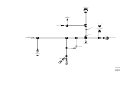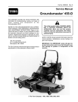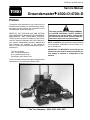
1
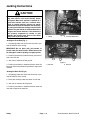
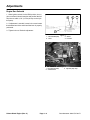
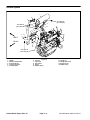
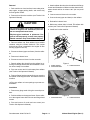
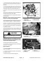
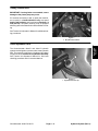
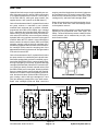
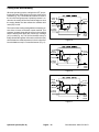
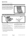
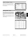
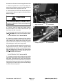
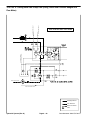
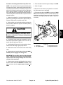
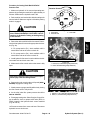
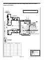
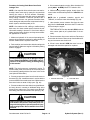
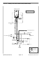
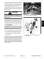
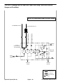
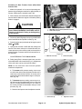
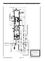
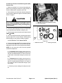
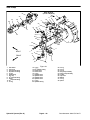
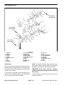
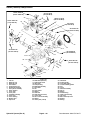
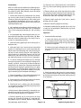
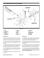
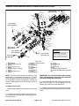
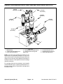
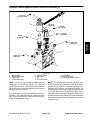
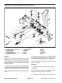
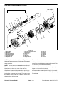
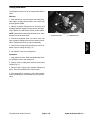
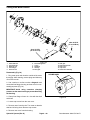
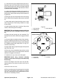
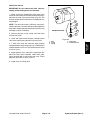
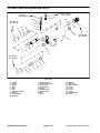
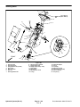
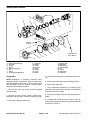
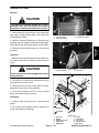
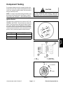
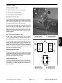
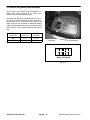
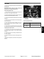
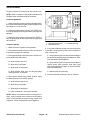
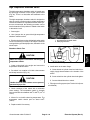
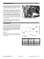
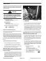
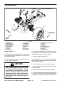
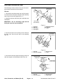
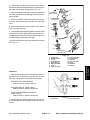
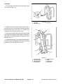
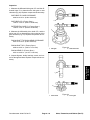
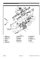
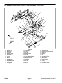
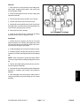
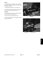
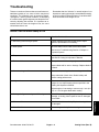
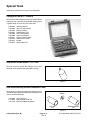
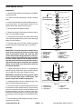
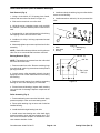
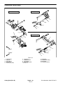
Procedure for Steering and Lift/Lower Gear Pump
Flow Test
Output from the steering and lift/lower gear pump section is equally divided by a proportional valve to provide
flow to the steering circuit and the lift circuit. To test gear
pump flow, testing of both circuits is required. Total gear
pump flow is the combined flow from the two circuits.
1. Make sure hydraulic oil is at normal operating temperature by operating the machine for approximately 10
minutes. Make sure the hydraulic tank is full.
7. If the total of the two flows is lower than 6.4 GPM or
a pressure of 1000 PSI could not be obtained, check for
restriction in pump intake line. If intake line is not restricted, remove gear pump and repair or replace as
necessary.
If the total of the two flows is 6.4 GPM but individual circuit flow is less than 3.2 GPM (e.g. steering circuit has
2 GPM and lift circuit has 4.4 GPM), suspect a problem
with the proportional valve in the gear pump.
2. Park machine on a level surface with the cutting units
lowered and off. Make sure engine is off and the parking
brake is engaged.
2
CAUTION
3
Figure 42
IMPORTANT: Make sure that the oil flow indicator
arrow on the flow gauge is showing that the oil will
flow from the pump, through the tester, and into the
hydraulic hose.
1. Gear pump
2. Lift circuit hose
3. With the engine off and cutting units lowered, install
tester in series between the last gear pump section and
one of the circuit hoses (Fig. 42). Make sure the tester
flow control valve is OPEN.
1
2
3
IMPORTANT: The pump is a positive displacement
type. If pump flow is completely restricted or
stopped, damage to the pump, tester, or other components could occur.
4
4. Start the engine and move throttle to full speed (2800
+ 50 RPM). DO NOT engage the cutting units.
5. While watching pressure gauges, slowly close flow
control valve until 1000 PSI is obtained on gauge. Verify
engine speed continues to be correct (2800 + 50 RPM).
3. Steering circuit hose
Figure 43
1. Gear pump backplate
2. Lift circuit
3. Steering circuit
4. Proportional valve
FLOW GAUGE READING TO BE: Flow approximately 3.2 GPM at 1000 PSI.
6. Stop engine. Remove tester and reinstall hydraulic
hose to gear pump. Complete steps 3 through 6 for other
circuit hose.
Groundsmaster 4500--D/4700--D
Page 4 -- 43
Hydraulic System (Rev. A)
Hydraulic
System
1
Prevent personal injury and/or damage to equipment. Read all WARNINGS, CAUTIONS, and Precautions for Hydraulic Testing at the beginning
of this section.