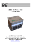
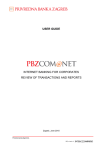
1
SERVICE MANUAL
FUELKARE
EEFS305A
SERIES-1
SERIES-1.5
SERIES-2
AEC GROUP
3600 WEST CARRIAGE DRIVE
SANTA ANA CA 92704
PH:877/906-1395
FAX:714/444-1395
1
TABLE OF CONTENTS
• IDENTIFY YOUR FUELKARE
4
• FUELKARE SERIES-1
1. CHAPTER-1: COMPONENT DESCRIPTION
• DISPLAY PANEL W/CIRCUIT BOARD ASSEMBLY
• LEVEL SENSOR
• PUMP ASSEMBLY
• MANIFOLD BLOCK ASSEMBLY
• FILTRATION
2. CHAPTER-2: PARTS & COMPONENTS
• MANIFOLD BLOCK ASSEMBLY
• PUMP ASSEMBLY
• DISPLAY PANEL W/ CIRCUIT BOARD ASSEMBLY
• TANK ASSEMBLY
• PARTS LIST ALPHABETIC
• PARTS LIST NUMERICAL
• FLOW DIAGRAMS
• COMPONENT POWER CHART
• WIRE DIAGRAMS
3. CHAPTER-3: THROUBLE SHOOTING
•
•
•
•
•
UNIT WILL NOT POWER UP
FAILS TO CALIBRATE AFTER POWER UP
DOES NOT FILL TANK
LOOSES PRESSURE DURING LEAK DOWN MODE
LOW PRESSURE DURING SERVICE MODE
5
5
5
6
6
7
8
9
10
11
12
13 – 19
20
21 – 23
24
24
24
25
26
4. CHAPTER-4: SERVICE PROCEDURES
•
•
•
REPLACING INTERNAL CHECK VALVE
REPLACING CIRCUIT BOARD
REPLACING PROCESSOR CHIP
27 – 30
31 – 33
35 – 37
• FUELKARE SERIES-1.5
1. CHAPTER-1: COMPONENT DESCRIPTION
•
•
•
•
•
DISPLAY PANEL W/ CIRCUIT BOARD ASSEMBLY
LEVEL SENSOR
PUMP ASSEMBLY
MANIFOLD BLOCK ASSEMBLY
FILTRATION
38
38
38
39
40
2. CHAPTER-2: PARTS & COMPONENTS
•
•
•
•
•
MANIFOLD BLOCK ASSEMBLY
PUMP ASSEMBLY
DISPLAY PANEL W/ CIRCUIT BOARD ASSEMBLY
TANK ASSEMBLY
PARTS LIST ALPHABETIC
2
41
42
43
44
45
TABLE OF CONTENTS
•
•
•
•
PARTS LIST NUMERICAL
FLOW DIAGRAMS
COMPONENT POWER CHART
WIRE DIAGRAMS
46
47 – 52
53
54 – 56
3. CHAPTER-3: THROUBLE SHOOTING
•
•
•
•
•
•
UNIT WILL NOT POWER UP
FAILS TO CALIBRATE AFTER POWER UP
DOES NOT FILL TANK
LOOSES PRESSURE DURING LEAK DOWN MODE
LOW PRESSURE DURING SERVICE MODE
HIGH PRESSURE DURING SERVICE MODE
57
57
57
58
59
59
4. CHAPTER-4: SERVICE PROCEDURES
•
•
•
REPLACING INTERNAL CHECK VALVE
REPLACING CIRCUIT BOARD
REPLACING PROCESSOR CHIP
60 - 63
64 – 66
67 – 70
• FUELKARE SERIES-2
1. CHAPTER-1; COMPONENT DESCRIPTION
• DISPLAY PANEL W/ CIRCUIT BOARD ASSEMBLY
• LEVEL SENSOR
• PUMP ASSEMBLY
• MANIFOLD BLOCK ASSEMBLY
• FILTRATION
2. CHAPTER-2: PARTS & COMPONENTS
• MANIFOLD BLOCK ASSEMBLY
• PUMP ASSEMBLY
• DISPLAY PANEL W/CIRCUIT BOARD ASSEMBLY
• TANK ASSEMBLY
• PARTS LIST ALPHABETICAL
• PARTS LIST NUMERICAL
• FLOW DIAGRAMS
• COMPONENT POWER CHART
• WIRE DIAGRAMS
3. CHAPTER-3: THROUBLE SHOOTING
• UNIT WILL NOT POWER UP
• FAILS TO CALIBRATE AFTER POWER UP
• DOES NOT FILL TANK
• LOOSES PRESSURE DURING LEAK DOWN MODE
• LOW PRESSURE DURING SERVICE MODE
• HIGH PRESSURE DURING SERVICE MODE
4. CHAPTER-4: SERVICE PROCEDURES
• REPLACING CIRCUIT BOARD FROM TOP
• REPLACING CIRCUIT BOARD FROM REAR
3
71
71
71
72
73
74
75
76
77
78
79
80 – 85
86
87 – 89
90
90
90
91
92
92
93 - 94
95 - 96
IDENTIFY YOUR FUELKARE
There are 3 versions of FUELKARE machines.
SERIES-1 : Single spin-on filter located under hose hanger.
SERIES-1.5: Has 2 filters, the spin-on filter located under hose hanger and the inline filter is
located towards bottom.
SERIES-2 Also has 2 filters but spin-on filter is located towards bottom and inline filter
below hose hanger.
CHAPTER 1
COMPONENT DESCRIPTION:
3030-01-01-0 DISPLAY PANEL W/CIRCUIT BOARD
ASSEMBLY
This assembly consists of 2 components.
1) 5135-00-01-2 Display mounting panel
w/overlay assy
2) 3030-01-00-0 Circuit board receives 12 vdc
through wire loom J1 upper 4 pins and powers
pump through J1 lower 4 pins. J2 wire loom
channels output signals to solenoids and audio
signal. J3 wire loom receives input signals from
pressure transducer and max level switch.
3113-58-50-8 LEVEL SENSOR ½”NPTM X 6”LEADS
Normally open reed switch with magnetic float
that closes the switch in presence of fluid, located
near the top of the tank and used to prevent tank
overfill.
Note: Install with red dot at 2 o-clock.
2246-22-11-0 PUMP ASSEMBLY(FUELKARE-1 / 1.5)
12 vdc gear pump with +/- 1 gpm flow rate
175 psi max pressure (magnetic clutch)
Fuelkare series-1
5
COMPONENT DESCRIPTION:
2141-98-12-4 MANIFOLD BLOCK ASSEMBLY
(FUELKARE-1) BLACK
A) 2136-30-20-3 RETURN VALVE, Normally
closed cartridge valve, open during 2 line service,
Soak(closed 250 millisecond when pulsing),
leak down test and to fill tank.
C) 3109-54-31-2
D) 2136-10-20-3
E) 2354-21-10-6
F) 2135-30-20-3
G) 2140-39-20-1
B) 2140-00-20-1 INTERNAL CHECK VALVE
open during diagnostic mode to return fuel to
vehicle gas tank.
PRESSURE TRANSDUCER, Measures pressure 0 – 175 psi.
BY-PASS VALVE, 1/32 orifice opens during purge to remove unwanted air from
internal lines and passages, and to perform 1 line service allowing return of
excess volume/pressure of cleaning solution mixture back to fuelkare tank.
FITTING ¼”MPT X 90 X 5/16” TUBE
PRESSURE VALVE, Normally open cartridge valve closes to perform dead head
test.
EXTERNAL CHECK VALVE, Prevents fuel to return to pump.
FILTRATION, 3 /Micron spin-on filter
Fuelkare series-1
6
CHAPTER 2
PARTS & COMPONENTS
MANIFOLD BLOCK ASSEMBLY
FUELKARE-1
2141-98-12-4
No.
A
B
C
D
E
F
G
PART NUMBER
2136-30-20-3
2140-00-20-1
3109-54-31-2
2136-10-20-3
2354-21-10-6
2135-30-20-3
2140-39-20-1
Fuelkare series-1
DESCRIPTION
RETURN SOLENOID VALVE ASSY (FUELKARE ALL)
CHECK VALVE INTERNAL 5 PSI (FUELKARE-1) S/S
PRESSURE TRANSDUCER ¼”MPT ASSEMBLY
BY-PASS VALVE 1/32” ORIFICE (FUELKARE-1)
FITTING ¼”MPT X 90 X 5/16”HOSE(NYLON)
PRESSURE SOLENOID VALVE ASSY (FUELKARE ALL)
CHECK VALVE EXTERNAL ¼”FPT X ¼”MPT(S/S)VITON
7
QTY.
1
1
1
1
2
1
1
CHAPTER 2
PARTS & COMPONENTS
PUMP ASSEMBLY
FUELKARE SERIES 1 AND 1.5
2246-22-11-0
No.
1
2
PART NUMBER
2247-22-10-0
2352-21-10-6
Fuelkare series-1
DESCRIPTION
PUMP, EXTERNAL GEAR 1/8”FPT X 12VDC(FUEL)
FITTING, 1/8”MPT X 90 X 5/16”HOSE(NYLON)
8
QTY.
1
2
CHAPTER 2
PARTS & COMPONENTS
DISPLAY PANEL W/CIRCUIT BOARD ASSEMBLY
3030-01-01-0
No.
1
2
3
4
PART NUMBER
5135-00-01-2
3030-01-00-0
1614-12-46-4
1011-99-00-8
Fuelkare series-1
DESCRIPTION
DISPLAY MOUNTING PANEL W/OVERLAY(FUELKARE)
CIRCUIT BOARD (FUELKARE)
STAND-OFF .250”OD X .172”ID X .461”LONG(ALUMINUM)
NUT 6-32 HEX (ZINC)
9
QTY
1
1
13
13
CHAPTER 2
PARTS & COMPONENTS
TANK, 1 GALLON ASSEMBLY (FUELKARE-1 & 1.5)
2262-44-11-1
No.
1
2
3
4
5
6
PART NUMBER
2262-44-10-1
3113-58-50-5
2354-21-10-6
2352-21-10-6
2293-00-90-1
2291-78-11-4
Fuelkare series-1
DESCRIPTION
TANK 1 GALLON (FUELKARE)
SENSOR LEVEL ½”MPT X 6” LEADS
FITTING, ¼”MPT X 90 X 5/16”HOSE (NYLON)
FITTING, 1/8”MPT X 90 X 5/16”HOSE (NYLON)
TANK TUBE .38” X 9.700” LONG (S/S)
CAP 1 ¾”ID TANK FUEL
10
QTY
1
1
1
1
1
1
CHAPTER 2
PARTS & COMPONENTS
ALPHABETICAL PART LIST
PART
NUMBER
3160-68-12-1
5120-11-00-2
3030-00-00-0
3030-01-00-0
3075-12-22-7
1615-03-16-8
3030-01-01-0
2354-20-10-6
2352-21-10-6
0901-54-90-2
0901-54-90-1
0904-53-10-1
2227-36-32-3
3142-10-03-1
3113-58-50-5
1029-95-00-8
3142-10-02-1
3142-10-01-1
3109-54-31-2
2246-22-11-0
2023-12-10-2
2023-13-10-2
1029-04-58-3
1017-10-56-8
2291-78-11-4
2262-44-11-1
2122-39-40-8
2136-10-20-3
2144-94-10-0
2135-30-20-3
2136-30-20-3
1631-09-61-2
1635-44-40-4
Fuelkare series-1
DESCRIPTION
AUDIO SIGNAL, 3-28VDC
AXLE (FUELKARE ALL)
CHIP, VER:7.58(FUELKARE-1)
CIRCUIT BOARD (FUELKARE ALL)
CORD/CLAMP ASSEMBLY 12VDC X 12' (RED/BLACK)
COTTERPIN, 1/8"OD X 1 1/4" LONG
DISPLAY & BOARD ASSEMBLY (FUELKARE ALL)
FITTING, 1/4"MPT X 90 X 5/16"HOSE (NYLON)
FITTING, 1/8"MPT X 90 X 5/16"HOSE (NYLON)
HOSE, 1/4"MPT X 90 X 10' PRESSURE ASSEMBLY(RED)HYTRON
HOSE, 1/4"MPT X 90 X 10' RETURN ASSEMBLY(BLACK)HYTRON
HOSE, 10' VACUUM(BLACK) RUBBER
HOUSING, FILTER ASSEMBLY (FUELKARE-1 , 1.5)
INPUT HARNESS "J3" (FUELKARE ALL)
LEVEL SENSOR 1/2"MPT X 6"LEADS
NUT, 1/4"-20 NYLOC HEX (ZINC)
OUTPUT HARNESS "J2" (FUELKARE ALL)
POWER HARNESS "J1"(FUELKARE ALL)
PRESSURE TRANSDUCER 1/4"MPT ASSEMBLY (NICKEL)
PUMP ASSEMBLY (FUELKARE-1 , 1.5) 12VDC
QUICK DISC, BODY S/23 X 1/4"FPT(VITON)NICKEL
QUICK DISC, BODY S/23 X 1/4"MPT(VITON)NICKEL
SCREW, 1/4"-20 X 3/8" BHCS ALLEN (BLACK)
SCREW, 10-32 X 3/8" PANHEAD PHILLIPS
TANK, CAP, 1 3/4"ID (FUELKARE ALL)
TANK, FUEL 1 GALLON ASSEMBLY (FUELKARE-1 , 1.5)
VALVE, BALL 1/4"MPT X 1/4"FPT WITH T-HANDLE (NICKEL)
VALVE, BY-PASS 1/32"ORIFICE (FUELKARE-1, 1.5)
VALVE, COIL 12VDC/14WATT FITS PARKER 08 SERIES
VALVE, PRESSURE ASSEMBLY(FUELKARE ALL)VITON
VALVE, RETURN ASSEMBLY (FUELKARE ALL)VITON
WHEEL, 9"OD X 3/4"WD X 1/2"BORE
WHEEL, CASTER 4"OD X 1 1/4"WD WITH BRAKE
11
CHAPTER 2
PARTS & COMPONENTS
NUMERICAL PART LIST
PART
NUMBER
0901-54-90-1
0901-54-90-2
0904-53-10-1
1017-10-56-8
1029-04-58-3
1029-95-00-8
1615-03-16-8
1631-09-61-2
1635-44-40-4
2023-12-10-2
2023-13-10-2
2122-39-40-8
2135-30-20-3
2136-10-20-3
2136-30-20-3
2144-94-10-0
2227-36-32-3
2246-22-11-0
2262-44-11-1
2291-78-11-4
2352-21-10-6
2354-20-10-6
3030-00-00-0
3030-01-00-0
3030-01-01-0
3075-12-22-7
3109-54-31-2
3113-58-50-5
3142-10-01-1
3142-10-02-1
3142-10-03-1
3160-68-12-1
5120-11-00-2
Fuelkare series-1
DESCRIPTION
HOSE, 1/4"MPT X 90 X 10' RETURN ASSEMBLY(BLACK)HYTRON
HOSE, 1/4"MPT X 90 X 10' PRESSURE ASSEMBLY(RED)HYTRON
HOSE, 10' VACUUM(BLACK) RUBBER
SCREW, 10-32 X 3/8" PANHEAD PHILLIPS
SCREW, 1/4"-20 X 3/8" BHCS ALLEN (BLACK)
NUT, 1/4"-20 NYLOC HEX (ZINC)
COTTERPIN, 1/8"OD X 1 1/4" LONG
WHEEL, 9"OD X 3/4"WD X 1/2"BORE
WHEEL, CASTER 4"OD X 1 1/4"WD WITH BRAKE
QUICK DISC, BODY S/23 X 1/4"FPT(VITON)NICKEL
QUICK DISC, BODY S/23 X 1/4"MPT(VITON)NICKEL
VALVE, BALL 1/4"MPT X 1/4"FPT WITH T-HANDLE (NICKEL)
VALVE, PRESSURE ASSEMBLY(FUELKARE ALL)VITON
VALVE, BY-PASS 1/32"ORIFICE (FUELKARE-1, 1.5)
VALVE, RETURN ASSEMBLY (FUELKARE ALL)VITON
VALVE, COIL 12VDC/14WATT FITS PARKER 08 SERIES
HOUSING, FILTER ASSEMBLY (FUELKARE-1 , 1.5)
PUMP ASSEMBLY (FUELKARE-1 , 1.5) 12VDC
TANK, FUEL 1 GALLON ASSEMBLY (FUELKARE-1 , 1.5)
TANK, CAP, 1 3/4"ID (FUELKARE ALL)
FITTING, 1/8"MPT X 90 X 5/16"HOSE (NYLON)
FITTING, 1/4"MPT X 90 X 5/16"HOSE (NYLON)
CHIP, VER:7.58(FUELKARE-1)
CIRCUIT BOARD (FUELKARE ALL)
DISPLAY & BOARD ASSEMBLY (FUELKARE ALL)
CORD/CLAMP ASSEMBLY 12VDC X 12' (RED/BLACK)
PRESSURE TRANSDUCER 1/4"MPT ASSEMBLY (NICKEL)
LEVEL SENSOR 1/2"MPT X 6"LEADS
POWER HARNESS "J1"(FUELKARE ALL)
OUTPUT HARNESS "J2" (FUELKARE ALL)
INPUT HARNESS "J3" (FUELKARE ALL)
AUDIO SIGNAL, 3-28VDC
AXLE (FUELKARE ALL)
12
FLOW DIAGRAM
Tank
Filter
OUT
Pum p
IN
Ext.
check
valve
U
W
Pressure
solenoid
Bypass
solenoid
L
L
Int.
check
valve
U
Return
solenoid
L
To return line
of vehicle
Pressure line (Red)
From fuel rail
outlet side (regulator)
Return line (Black)
DIAGNOSTIC MODE
ENGINE RUNNING NO KEYS “PRESSED”
2 LINE SERVICE
Fuelkare series-1
13
FLOW DIAGRAM
Tank
Filter
OUT
Pump
IN
Ext.
check
valve
Pressure
solenoid
U
W
Bypass
solenoid
L
L
Int.
check
valve
U
Return
solenoid
L
Pressure line (Red)
From outlet side
of fuel rail
Return line (Black)
DIAGNOSTIC MODE
ENGINE RUNNING NO KEYS “PRESSED”
1 LINE SERVICE
Fuelkare series-1
14
FLOW DIAGRAM
Tank
Filter
OUT
Pum p
IN
Ext.
check
valve
U
W
Pressure
solenoid
Bypass
solenoid
L
L
Int.
check
valve
U
Return
solenoid
L
Pressure line (Red)
From outlet side
of fuel rail
Return line (Black)
DIAGNOSTIC/FILL MODE
ENGINE RUNNING FILL TANK “PRESSED”
Fuelkare series-1
15
FLOW DIAGRAM
Tank
Filter
OUT
Pump
IN
Ext.
check
valve
Pressure
solenoid
U
W
Bypass
solenoid
L
L
Int.
check
valve
U
Return
solenoid
L
Pressure line (Red)
From outlet side
of fuel rail
Return line (Black)
DIAGNOSTIC MODE
ENGINE RUNNING
DEADHEAD KEY “PRESSED”
Fuelkare series-1
16
FLOW DIAGRAM
Tank
Filter
OUT
Pump
IN
Ext.
check
valve
U
W
Pressure
solenoid
Bypass
solenoid
L
L
Int.
check
valve
To inlet side
of fuel rail
U
Return
solenoid
L
Pressure line (Red)
To vehicle's
fuel pump
From return side
of fuel rail (regulator)
Return line (Black)
DIAGNOSTIC MODE
LEAKDOWN TEST
Fuelkare series-1
17
FLOW DIAGRAM
Tank
Filter
OUT
Pum p
IN
Ext.
check
valve
W
W
Pressure
solenoid
Bypass
solenoid
L
L
Int.
check
valve
W
Return
solenoid
L
To inlet
side of fuel rail
Pressure line (Red)
From outlet side
of fuel rail
(regulator)
Return line (Black)
2 LINE SERVICE
Fuelkare series-1
18
FLOW DIAGRAM
Tank
Filter
OUT
Pum p
IN
Ext.
check
valve
U
W
Pressure
solenoid
Bypass
solenoid
L
L
Int.
check
valve
U
Return
solenoid
L
To fuel
rail
Pressure line (Red)
N/A
Return line (Black)
1 LINE SERVICE
Fuelkare series-1
19
CHAPTER 2
PARTS & COMPONENTS
COMPONENT POWER CHART
FILL TANK
FLOW RATE CHECK
DEADHEAD
PRESSURE CHECK
LEAKDOWN
PURGE
LEAKDOWN
TEST
2 LINE
SERVICE
1 LINE
SERVICE
Fuelkare series-1
RETURN
SOLENOID
VALVE
PRESSURE
SOLENOID
VALVE
BY-PASS
SOLENOID
VALVE
PUMP
ON
OFF
OFF
ON
ON
OFF
OFF
ON
OFF
OFF
OFF
OFF
OFF
OFF
ON
OFF
OFF
ON
OFF
OFF
ON
ON
ON
ON
20
WIRE DIAGRAMS
Fuelkare series-1
21
WIRE DIAGRAMS
Fuelkare series-1
22
WIRE DIAGRAMS
Fuelkare series-1
23
CHAPTER 3
THROUBLE SHOOTING
UNIT WILL NOT POWER UP
1. Verify that power leads are securely connected to a 12VDC power source(car battery)
2. Verify proper connection. Black lead to ground and red lead to positive. Make sure connections
are clean.
3. Check for battery power at ‘J1’ connector pins 1, 2 and 3, 4 red and black wires.
-If no battery power is detected at ‘J1’ connector, check internal connection between power
cord and ‘J1’ wire loom, repair or replace as needed.
FAILS TO CALIBRATE AFTER POWER-UP
1. If Fuelkare black and red hoses where connected before power-up, remove hoses from fuel
system and connect 2 open end adapters to red and black hose.
- If still no calibration, using shop air apply short bursts of pressure to red hose this should
reset transducer.
- If still no calibration check connection to ‘J3’ wire loom
- If connection is correct, replace pressure transducer.
DOES NOT FILL TANK
1. First time use will take up to 60 seconds (on a properly functioning vehicle’s fuel supply system)
to prime filter and lines.
2. Verify that hoses and adapters are properly connected to vehicle fuel system.
3. If properly connected to fuel system, check return solenoid assembly for 12vdc.
-If 12VDC is not present, check ‘J2’ wire loom repair or replace as needed.
-If 12VDC is present remove return solenoid assembly and apply power to see if plunger retracts.
-If not push center of plunger several times with Phillips screw driver and clean with compressed
air, re-power solenoid valve assembly and check plunger movement.
-If plunger moves freely, reinstall and repeat fill tank mode.
-If plunger does not move freely replace solenoid assembly.
Fuelkare series-1
24
CHAPTER 3
THROUBLE SHOOTING
LOOSES PRESSURE DURING LEAKDOWN MODE
1. Remove Fuelkare red and black hoses from vehicle and press leak down test key, pressure should
ramp up to +/- 100 p.s.i. once achieved, the pressure displayed will alternately show baseline
and current pressure. Normal acceptable decay is 10% @ 100 p.s.i. over one minute. If holding
pressure problem with vehicle.
- If not holding pressure, perform the following.
2. Press and release the STOP key to relieve pressure.
3. Install open end adapters to red and black hoses.
4. Remove Fuelkare tank cap and insert red hose with adapter in new fluid tank.
5. Using shop air and an appropriate blow gun, blow air into adapter now attached to black hose.
Continue blowing until red hose is empty.
6. Using shop air, apply short bursts of pressure to red hose to reseat internal check valve.
7. Remove adapters from black and red hoses; connect black and red hoses together with male loop
adapter p/n: 6016-02-01-1; press and release leak down test key to restore cleaning solution to
the now cleared pathway through the machine and hoses. When pumps stops remove loop from
black and red hoses.
8. Retest leak down mode.
-If not holding pressure,
9. Remove rear panel
10. Press leak down key, monitor clear tube between manifold and pump and monitor clear tube
between manifold and tank for fluid flow
-If fluid flows from manifold to pump
11. Unscrew white nylon nut from clear tube on output side of pump
12. Install adapter on red hose and insert hose in new fluid tank
13. Using shop air blow into clear tube until red hose is empty.
14. Take red hose with adapter and apply short bursts of air to reseat external check valve
15. Reattach clear tube to pump and press leak down test key fluid will circulate through red hose
repeat if needed to remove air from system.
16. Remove adapter from red hose.
17. Retest leak down mode
-If fluid flows from manifold to tank
18. Remove internal check valve, inspect for debris and condition of O-rings
or replace if needed.
Fuelkare series-1
25
CHAPTER 3
THROUBLE SHOOTING
LOW PRESSURE DURING SERVICE MODE
1.
2.
3.
4.
5.
6.
7.
8.
Check filter replacement history (+/- 50 services per filter).
Remove hoses from vehicle.
Install open end adapters to red and black hose.
Insert red hose to new fluid tank.
Using shop air, pressurize black hose until red hose is empty.
Using shop air, apply short bursts of pressure to red hose to reseat internal check valve.
Reconnect red and black hoses to vehicle.
Resume service.
Fuelkare series-1
26
CHAPTER 4
SERVICE PROCEDURES
REPLACING INTERNAL CHECK VALVE
1. Remove the Phillips Head pan screws from the center back panel;
2. Remove the two (2) 5/32” Allen Head screws in filter cavity; a 4mm Allen Socket will also fit
these 2 screw heads
3. Remove the nickel plated hex head bolt threaded into the top of the black anodized Manifold
Block (7/8” across the flats);
Fuelkare series-1
27
CHAPTER 4
SERVICE PROCEDURES
REPLACING INTERNAL CHECK VALVE
Fuelkare series-1
28
CHAPTER 4
SERVICE PROCEDURES
REPLACING INTERNAL CHECK VALVE
4. Take a pick tool and work the check valve from the manifold block (it is held in with an "Oring" interference fit) by inserting the tip of the tool, alternately, in the offsetting holes in the top
of the check valve.
Fuelkare series-1
29
CHAPTER 4
SERVICE PROCEDURES
REPLACING INTERNAL CHECK VALVE
Insure there are no contaminants in the manifold block; insert the new check valve in the
manifold block. The correct orientation is with the “holes up” as described in the removal
process. Firmly seat to bottom of block and replace the retainer bolt.
This process takes maybe ten minutes and can also be tested by powering up the unit; hooking
the red and black hoses together with the 6016-02-01-1 extension (double male) adapter;
Press + and - buttons simultaneously (Version 7.56 software only) for three seconds to bypass
diagnostics;
Press "Two Line" button; press "Start Soak" button and watch the air disappear from the plastic
hoses inside the machine. Your pressure display will indicate 16 p.s.i. (or thereabout, depending
on battery voltage and the resulting pump speed), which is enough pressure to continue the
simulation without crimping hoses.
Press the "Set Time" button until you round the clock back to 0 minutes, shortly after which the
process will time out and stop. Paying attention to the lines inside the machine, you will note that
no air reappears and the lines do not "drain down".
Remove the extension adapter from the red and black hoses with a shop towel handy to catch the
solution that escapes from the adapter.
Replace the back cover and retaining screws to complete the process.
Fuelkare series-1
30
CHAPTER 4
SERVICE PROCEDURES
REPLACING CIRCUIT BOARD
1. Remove rear center panel, 9 Phillips screws.
2. Remove 2 Allen head ¼”-20 screws using 5/32” Allen wrench.
Fuelkare series-1
31
CHAPTER 4
SERVICE PROCEDURES
REPLACING CIRCUIT BOARD
3. Remove the 4 nyloc nuts securing the front control board assembly using long extension with 3/8”
Socket.
4. Disconnect wire connectors from board, if not marked J1, J2, J3 please mark before removal.
Fuelkare series-1
32
CHAPTER 4
SERVICE PROCEDURES
REPLACING CIRCUIT BOARD
5. Place board assembly on top of unit and remove screws or nuts to separate circuit board from display
panel
6. Replace circuit board
7. Reassemble and test.
Fuelkare series-1
33
CHAPTER 4
SERVICE PROCEDURES
REPLACING PROCESSOR CHIP
1. Remove rear center panel, 9 Phillips screws.
2. Remove 2 Allen head ¼”-20 screws using 5/32” Allen wrench.
Fuelkare series-1
34
CHAPTER 4
SERVICE PROCEDURES
REPLACING PROCESSOR CHIP
3. Remove the 4 nyloc nuts securing the front control board assembly using long extension with 3/8”
Socket.
4. Disconnect wire connectors from board, if not marked J1, J2, J3 please mark before removal.
Fuelkare series-1
35
CHAPTER 4
SERVICE PROCEDURES
REPLACING PROCESSOR CHIP
5. Place board assembly on top of unit and remove screws or nuts to separate circuit board from display
panel
6. Remove processor chip from board using chip puller or tool that came with new chip.
Fuelkare series-1
36
CHAPTER 4
SERVICE PROCEDURES
REPLACING PROCESSOR CHIP
7. Pay close attention: Find the flat corner of the new processor chip and flat corner of socket.
8. Insert new processor chip into socket.
9. Reassemble board to display panel, connect wires to board and test before closing up machine
Fuelkare series-1
37
CHAPTER 1
COMPONENT DESCRIPTION:
3030-01-01-0 DISPLAY PANEL W/CIRCUIT BOARD
ASSEMBLY
This assembly consists of 2 components.
1) 5135-00-01-2 Display mounting panel w/overlay
assy
2) 3030-01-00-0 Circuit board receives 12 vdc
through wire loom J1 upper 4 pins and powers
pump through J1 lower 4 pins. J2 wire loom
channels output signals to solenoids and audio
signal. J3 wire loom receives input signals from
pressure transducer and max level switch.
3113-58-50-8 LEVEL SENSOR ½”NPTM X 6”LEADS
Normally open reed switch with magnetic float
that closes the switch in presence of fluid, located
near the top of the tank and used to prevent tank
overfill.
Note: Install with red dot at 2 o-clock.
2246-22-11-0 PUMP ASSEMBLY(FUELKARE-1 / 1.5)
12 vdc gear pump with +/- 1 gpm flow rate
175 psi max pressure (magnetic clutch)
Fuelkare series-1.5
38
CHAPTER 1
COMPONENT DESCRIPTION:
2141-98-13-4 MANIFOLD BLOCK ASSEMBLY (FUELKARE-1.5) BLACK
A) 2136-30-20-3 RETURN VALVE, Normally closed cartridge valve, open during 2 line
service, leakdown test and to fill tank.
B) 2140-00-20-1 INTERNAL CHECK VALVE open during diagnostic mode to return fuel
to vehicle gas tank.
C) 3109-54-31-2 PRESSURE TRANSDUCER, Measures and monitors pressure 0 – 175 psi.
D) 2136-10-20-3 BY-PASS VALVE, 1/32 orifice opens during purge and to perform 1 line service.
E) 2354-21-10-6 FITTING ¼”MPT X 90 X 5/16” TUBE
F) 2135-30-20-3 PRESSURE VALVE, Normally open cartridge valve closes to perform dead head
test.
G) 2140-39-20-1 EXTERNAL CHECK VALVE, Prevents fuel to return to pump.
H) 2354-31-14-1 FITTING, POLY ¼”MPT X 90 X 3/8” HOSE
Fuelkare series-1.5
39
CHAPTER 1
COMPONENT DESCRIPTION:
FILTRATION
A) EEFS308A5
B) 0600-01-00-0
Fuelkare series-1.5
3 Micron spin-on filter kit (2 pieces)
This filters all fluid returning from vehicle
Inline fuel filter 3/8”barb x 3/8”barb
This filters all fluid leaving the fuelkares tank.
40
CHAPTER 2
PARTS & COMPONENTS
MANIFOLD BLOCK ASSEMBLY
FUELKARE-1.5
2141-98-13-4
No PARTNUMBER
.
A 2136-30-20-3
B
2140-00-20-1
C 3109-54-31-2
D 2136-10-20-3
E
2354-21-10-6
F
2135-30-20-3
G 2140-39-20-1
H 2354-31-14-1
Fuelkare series-1.5
DESCRIPTION
QTY
RETURN VALVE ASSY (FUELKARE ALL)
CHECK VALVE INTERNAL 5 PSI (FUELKARE-1)S/S
PRESSURE DRANSDUCER ¼”MPT ASSEMBLY
BY-PASS VALVE 1/32” ORIFICE (FUELKARE-1)
FITTING ¼”MPT X 90 X 5/16” HOSE (NYLON)
PRESSURE VALVE ASSY (FUELKARE ALL)
CHECK VALVE EXTERNAL ¼”MPT X ¼”FPT(S/S)VITON
FITTING POLY ¼”MPT X 90 X 3/8” HOSE
41
1
1
1
1
2
1
1
1
CHAPTER 2
PARTS & COMPONENTS
PUMP ASSEMBLY
FUELKARE SERIES 1 AND 1.5
2246-22-11-0
No.
1
2
PART NUMBER
2247-22-10-0
2352-21-10-6
Fuelkare series-1.5
DESCRIPTION
PUMP, EXTERNAL GEAR 1/8”FPT X 12VDC(FUEL)
FITTING, 1/8”MPT X 90 X 5/16”HOSE(NYLON)
42
QTY.
1
2
CHAPTER 2
PARTS & COMPONENTS
DISPLAY PANEL W/CIRCUIT BOARD ASSEMBLY
3030-01-01-0
No.
1
2
3
4
PART NUMBER
5135-00-01-2
3030-01-00-0
1614-12-46-4
1011-99-00-8
Fuelkare series-1.5
DESCRIPTION
DISPLAY MOUNTING PANEL W/OVERLAY(FUELKARE)
CIRCUIT BOARD (FUELKARE)
STAND-OFF .250”OD X .172”ID X .461”LONG(ALUMINUM)
NUT 6-32 HEX (ZINC)
43
QTY
1
1
13
13
CHAPTER 2
PARTS & COMPONENTS
TANK, 1 GALLON ASSEMBLY (FUELKARE-1 & 1.5)
2262-44-11-1
No.
1
2
3
4
5
6
PART NUMBER
2262-44-10-1
3113-58-50-5
2354-21-10-6
2352-21-10-6
2293-00-90-1
2291-78-11-4
Fuelkare series-1.5
DESCRIPTION
TANK 1 GALLON (FUELKARE)
SENSOR LEVEL ½”MPT X 6” LEADS
FITTING, ¼”MPT X 90 X 5/16”HOSE (NYLON)
FITTING, 1/8”MPT X 90 X 5/16”HOSE (NYLON)
TANK TUBE .38” X 9.700” LONG (S/S)
CAP 1 ¾”ID TANK FUEL
44
QTY
1
1
1
1
1
1
CHAPTER 2
PARTS & COMPONENTS
ALPHABETICAL PART LIST
PART
NUMBER
3160-68-12-1
5120-11-00-2
3030-00-00-0
3030-01-00-0
3075-12-22-7
1615-03-16-8
3030-01-01-0
2354-20-10-6
2352-21-10-6
0901-54-90-2
0901-54-90-1
0904-53-10-1
2227-36-32-3
3142-10-03-1
3113-58-50-5
1029-95-00-8
3142-10-02-1
3142-10-01-1
3109-54-31-2
2246-22-11-0
2023-12-10-2
2023-13-10-2
1029-04-58-3
1017-10-56-8
2291-78-11-4
2262-44-11-1
2122-39-40-8
2136-10-20-3
2144-94-10-0
2135-30-20-3
2136-30-20-3
1631-09-61-2
1635-44-40-4
Fuelkare series-1.5
DESCRIPTION
AUDIO SIGNAL, 3-28VDC
AXLE (FUELKARE ALL)
CHIP, VER:7.58(FUELKARE-1)
CIRCUIT BOARD (FUELKARE ALL)
CORD/CLAMP ASSEMBLY 12VDC X 12' (RED/BLACK)
COTTERPIN, 1/8"OD X 1 1/4" LONG
DISPLAY & BOARD ASSEMBLY (FUELKARE ALL)
FITTING, 1/4"MPT X 90 X 5/16"HOSE (NYLON)
FITTING, 1/8"MPT X 90 X 5/16"HOSE (NYLON)
HOSE, 1/4"MPT X 90 X 10' PRESSURE ASSEMBLY(RED)HYTRON
HOSE, 1/4"MPT X 90 X 10' RETURN ASSEMBLY(BLACK)HYTRON
HOSE, 10' VACUUM(BLACK) RUBBER
HOUSING, FILTER ASSEMBLY (FUELKARE-1 , 1.5)
INPUT HARNESS "J3" (FUELKARE ALL)
LEVEL SENSOR 1/2"MPT X 6"LEADS
NUT, 1/4"-20 NYLOC HEX (ZINC)
OUTPUT HARNESS "J2" (FUELKARE ALL)
POWER HARNESS "J1"(FUELKARE ALL)
PRESSURE TRANSDUCER 1/4"MPT ASSEMBLY (NICKEL)
PUMP ASSEMBLY (FUELKARE-1 , 1.5) 12VDC
QUICK DISC, BODY S/23 X 1/4"FPT(VITON)NICKEL
QUICK DISC, BODY S/23 X 1/4"MPT(VITON)NICKEL
SCREW, 1/4"-20 X 3/8" BHCS ALLEN (BLACK)
SCREW, 10-32 X 3/8" PANHEAD PHILLIPS
TANK, CAP, 1 3/4"ID (FUELKARE ALL)
TANK, FUEL 1 GALLON ASSEMBLY (FUELKARE-1 , 1.5)
VALVE, BALL 1/4"MPT X 1/4"FPT WITH T-HANDLE (NICKEL)
VALVE, BY-PASS 1/32"ORIFICE (FUELKARE-1, 1.5)
VALVE, COIL 12VDC/14WATT FITS PARKER 08 SERIES
VALVE, PRESSURE ASSEMBLY(FUELKARE ALL)VITON
VALVE, RETURN ASSEMBLY (FUELKARE ALL)VITON
WHEEL, 9"OD X 3/4"WD X 1/2"BORE
WHEEL, CASTER 4"OD X 1 1/4"WD WITH BRAKE
45
CHAPTER 2
PARTS & COMPONENTS
NUMERICAL PART LIST
PART
NUMBER
0901-54-90-1
0901-54-90-2
0904-53-10-1
1017-10-56-8
1029-04-58-3
1029-95-00-8
1615-03-16-8
1631-09-61-2
1635-44-40-4
2023-12-10-2
2023-13-10-2
2122-39-40-8
2135-30-20-3
2136-10-20-3
2136-30-20-3
2144-94-10-0
2227-36-32-3
2246-22-11-0
2262-44-11-1
2291-78-11-4
2352-21-10-6
2354-20-10-6
3030-00-00-0
3030-01-00-0
3030-01-01-0
3075-12-22-7
3109-54-31-2
3113-58-50-5
3142-10-01-1
3142-10-02-1
3142-10-03-1
3160-68-12-1
5120-11-00-2
Fuelkare series-1.5
DESCRIPTION
HOSE, 1/4"MPT X 90 X 10' RETURN ASSEMBLY(BLACK)HYTRON
HOSE, 1/4"MPT X 90 X 10' PRESSURE ASSEMBLY(RED)HYTRON
HOSE, 10' VACUUM(BLACK) RUBBER
SCREW, 10-32 X 3/8" PANHEAD PHILLIPS
SCREW, 1/4"-20 X 3/8" BHCS ALLEN (BLACK)
NUT, 1/4"-20 NYLOC HEX (ZINC)
COTTERPIN, 1/8"OD X 1 1/4" LONG
WHEEL, 9"OD X 3/4"WD X 1/2"BORE
WHEEL, CASTER 4"OD X 1 1/4"WD WITH BRAKE
QUICK DISC, BODY S/23 X 1/4"FPT(VITON)NICKEL
QUICK DISC, BODY S/23 X 1/4"MPT(VITON)NICKEL
VALVE, BALL 1/4"MPT X 1/4"FPT WITH T-HANDLE (NICKEL)
VALVE, PRESSURE ASSEMBLY(FUELKARE ALL)VITON
VALVE, BY-PASS 1/32"ORIFICE (FUELKARE-1, 1.5)
VALVE, RETURN ASSEMBLY (FUELKARE ALL)VITON
VALVE, COIL 12VDC/14WATT FITS PARKER 08 SERIES
HOUSING, FILTER ASSEMBLY (FUELKARE-1 , 1.5)
PUMP ASSEMBLY (FUELKARE-1 , 1.5) 12VDC
TANK, FUEL 1 GALLON ASSEMBLY (FUELKARE-1 , 1.5)
TANK, CAP, 1 3/4"ID (FUELKARE ALL)
FITTING, 1/8"MPT X 90 X 5/16"HOSE (NYLON)
FITTING, 1/4"MPT X 90 X 5/16"HOSE (NYLON)
CHIP, VER:7.58(FUELKARE-1)
CIRCUIT BOARD (FUELKARE ALL)
DISPLAY & BOARD ASSEMBLY (FUELKARE ALL)
CORD/CLAMP ASSEMBLY 12VDC X 12' (RED/BLACK)
PRESSURE TRANSDUCER 1/4"MPT ASSEMBLY (NICKEL)
LEVEL SENSOR 1/2"MPT X 6"LEADS
POWER HARNESS "J1"(FUELKARE ALL)
OUTPUT HARNESS "J2" (FUELKARE ALL)
INPUT HARNESS "J3" (FUELKARE ALL)
AUDIO SIGNAL, 3-28VDC
AXLE (FUELKARE ALL)
46
FLOW DIAGRAM
Filter
Tank
OUT
Pum p
IN
Bulkhead
Inline filter
Bulkhead
Ext.
check
valve
U
Pressure
solenoid
Bypass
solenoid
L
Int.
check
valve
U
Return
solenoid
L
Bulkhead
Pressure
To
Line
return line
of vehicle (tank)
Return
From out side
of fuel rail (regulator)
Line
DIAGNOSTIC MODE
ENGINE RUNNING NO KEYS “PRESSED”
Fuelkare series-1.5
47
Bulkhead
FLOW DIAGRAM
Filter
Tank
OUT
Pum p
IN
Bulkhead
Inline filter
Bulkhead
Ext.
check
valve
Pressure
solenoid
U
Bypass
solenoid
L
Int.
check
valve
U
Return
solenoid
L
Bulkhead
Pressure
Line
Return
From
Line
outlet side
of fuel rail (regulator)
DIAGNOSTIC/FILL MODE
ENGINE RUNNING FILL TANK “PRESSED”
Fuelkare series-1.5
48
Bulkhead
FLOW DIAGRAM
Filter
Tank
OUT
Pum p
IN
Bulkhead
Inline filter
Bulkhead
Ext.
check
valve
Pressure
solenoid
U
Bypass
solenoid
L
Int.
check
valve
U
Return
solenoid
L
Bulkhead
Pressure
Line
Return
Line
DIAGNOSTIC MODE
ENGINE RUNNING
DEADHEAD KEY “PRESSED”
Fuelkare series-1.5
49
Bulkhead
FLOW DIAGRAM
Filter
Tank
OUT
Pum p
IN
Bulkhead
Inline filter
Bulkhead
Ext.
check
valve
U
Pressure
solenoid
Bypass
solenoid
L
Int.
check
valve
To inlet side
of fuel rail
U
Return
solenoid
L
Bulkhead
Pressure
Line
Return
From
Line
return side
of fuel rail (regulator)
DIAGNOSTIC M ODE
LEAKDOWN TEST
To vehicles
fuel pump
DIAGNOSTIC MODE
LEAKDOWN TEST
Fuelkare series-1.5
50
Bulkhead
FLOW DIAGRAM
Filter
Tank
OUT
Pum p
IN
Bulkhead
Inline filter
Bulkhead
Ext.
check
valve
U
Pressure
solenoid
Bypass
solenoid
L
Int.
check
valve
U
Return
solenoid
L
To
inlet side
of fuel rail
Bulkhead
Pressure
Line
Return
From
outlet side
of fuel rail
2 LINE SERVICE
Fuelkare series-1.5
51
Line
Bulkhead
FLOW DIAGRAM
Filter
Tank
OUT
Pum p
IN
Bulkhead
Inline filter
Bulkhead
Ext.
check
valve
U
Pressure
solenoid
Bypass
solenoid
L
Int.
check
valve
U
Return
solenoid
L
To
fuel rail
Bulkhead
Pressure
Line
Return
Line
1 LINE SERVICE
Fuelkare series-1.5
52
Bulkhead
CHAPTER 2
PARTS & COMPONENTS
COMPONENT POWER CHART
FILL TANK
FLOW RATE CHECK
DEADHEAD
PRESSURE CHECK
LEAKDOWN
PURGE
LEAKDOWN
TEST
2 LINE
SERVICE
1 LINE
SERVICE
Fuelkare series-1.5
RETURN
SOLENOID
PRESSURE
SOLENOID
BY-PASS
SOLENOID
PUMP
ON
OFF
OFF
ON
ON
OFF
OFF
ON
OFF
OFF
OFF
OFF
OFF
OFF
ON
OFF
OFF
ON
OFF
OFF
ON
ON
ON
ON
53
WIRE DIAGRAMS
Fuelkare series-1.5
54
WIRE DIAGRAMS
Fuelkare series-1.5
55
WIRE DIAGRAMS
Fuelkare series-1.5
56
2/1/2006
CHAPTER 3
THROUBLE SHOOTING
UNIT WILL NOT POWER UP
1. Verify that power leads are securely connected to a 12VDC power source(car battery)
2. Verify proper connection. Black lead to ground and red lead to positive. Make sure connections
are clean.
3. Check for battery power at ‘J1’ connector pins 1, 2 and 3, 4 red and black wires.
-If no battery power is detected at ‘J1’ connector, check internal connection between power
cord and ‘J1’ wire loom, repair or replace as needed.
FAILS TO CALIBRATE AFTER POWER-UP
1. If Fuelkare black and red hoses where connected before power-up, remove hoses from fuel
system and connect 2 open end adapters to red and black hose.
- If still no calibration, using shop air apply short bursts of pressure to red hose this should
reset transducer.
- If still no calibration check connection to ‘J3’ wire loom
- If connection is correct, replace pressure transducer.
DOES NOT FILL TANK
1. First time use will take up to 60 seconds (on a properly functioning vehicle’s fuel supply system)
to prime filter and lines.
2. Verify that hoses and adapters are properly connected to vehicle fuel system.
3. If properly connected to fuel system check return solenoid assembly for 12vdc.
-If 12VDC is not present, check ‘J2’ wire loom repair or replace as needed.
-If 12VDC is present remove return solenoid assembly and apply power to see if plunger retracts.
-If not push center of plunger several times with Phillips screw driver and clean with compressed
air, re-power solenoid assembly and check plunger movement.
-If plunger moves freely, reinstall and repeat fill tank mode.
-If plunger does not move freely replace solenoid assembly.
Fuelkare series-1.5
57
2/1/2006
CHAPTER 3
THROUBLE SHOOTING
LOOSES PRESSURE DURING LEAKDOWN MODE
1. Remove Fuelkare red and black hoses from vehicle and press leak down test key, pressure should
ramp up to +/- 100 p.s.i. once archieved, the pressure displayed will alternately show baseline
and current pressure. Normal acceptable decay is 10% @ 100. psi over 1 minute. If holding
pressure problem with vehicle.
- If not holding pressure, perform the following.
2. Press and release the STOP key to relieve pressure.
3. Install open end adapters to red hose.
4. Remove fuelkare tank cap and insert red hose with adapter in new fluid tank.
5. Remove spin-on filter
6. Using shop air and an appropriate blow gun, blow air into center port of spin-on filter housing
until red hose is empty.
7. Using shop air, apply short bursts of pressure to red hose to reseat internal check valve.
8. Remove adapter from red hose and reinstall spin-on filter.
9. Loop black and red hoses using male loop p/n:6016-02-01-1; press and release leak down key to
restore cleaning solution to the now cleared pathway through the machine and hoses. When
pump stops remove loop from black and red hoses.
10. Re test leak down mode
-If not holding pressure,
11. Remove rear panel
12. Press leak down key, monitor clear tube between manifold and pump and monitor clear tube
between manifold and tank for fluid flow
-If fluid flows from manifold to pump
13 Unscrew white nylon nut from clear tube on output side of pump
14. Install adapter on red hose and insert hose in new fluid tank
15. Using shop air blow into clear tube until red hose is empty.
16. Take red hose with adapter and apply short bursts of air to reseat external check valve
17. Reattach clear tube to pump and press leak down fluid will circulate through red hose repeat if
needed to remove air from system.
18. Remove adapter from red hose.
19. Retest leak down mode
-If fluid flows from manifold to tank
20. Remove internal check valve, inspect for debris and condition of O-rings
or replace if needed.
Fuelkare series-1.5
58
2/1/2006
CHAPTER 3
THROUBLE SHOOTING
LOW PRESSURE DURING SERVICE MODE
1.
2.
3.
4.
5.
6.
Check inline filter replacement history (+/- 50 services per filter).
Remove hoses from vehicle.
Install open end adapters to red hose.
Insert red hose to new fluid tank.
Repower Fuelkare.
Once diagnostic / fill cycle led is flashing Press and hold + and – keys until 2 line and 1 line
service led start flashing.
7. Press 2 line key
8. Press start soak key and monitor flow through red hose
9. If flow is low or stops with pump still running replace inline filter.
NOTE: Whene replacing inline filter it is recommended to clean line from filter to tank.
Remove cap from tank and apply shop air to line, check tank for debris and clean if
needed.
HIGH PRESSURE DURING SERVICE
1.
2.
3.
4.
Check for kinked hoses.
Check if red hose is properly connected to adapter.
Change ultra fine spin-on filter.
Resume service.
Fuelkare series-1.5
59
CHAPTER 4
SERVICE PROCEDURES
REPLACING INTERNAL CHECK VALVE
1. Remove the Phillips Head pan screws from the center back panel;
2. Remove the two (2) 5/32” Allen Head screws in filter cavity; a 4mm Allen Socket will also fit
these 2 screw heads
3. Remove the nickel plated hex head bolt threaded into the top of the black anodized Manifold
Block (7/8” across the flats);
Fuelkare series 1.5
60
CHAPTER 4
SERVICE PROCEDURES
REPLACING INTERNAL CHECK VALVE
Fuelkare series 1.5
61
CHAPTER 4
SERVICE PROCEDURES
REPLACING INTERNAL CHECK VALVE
4. Take a pick tool and work the check valve from the manifold block (it is held in with an "Oring" interference fit) by inserting the tip of the tool, alternately, in the offsetting holes in the top
of the check valve.
Fuelkare series 1.5
62
CHAPTER 4
SERVICE PROCEDURES
REPLACING INTERNAL CHECK VALVE
Insure there are no contaminants in the manifold block; insert the new check valve in the
manifold block. The correct orientation is with the “holes up” as described in the removal
process. Firmly seat to bottom of block and replace the retainer bolt.
This process takes maybe ten minutes and can also be tested by powering up the unit; hooking
the red and black hoses together with the 6016-02-01-1 extension (double male) adapter;
Press + and - buttons simultaneously (Version 7.56 software only) for three seconds to bypass
diagnostics;
Press "Two Line" button; press "Start Soak" button and watch the air disappear from the plastic
hoses inside the machine. Your pressure display will indicate 16 p.s.i. (or thereabout, depending
on battery voltage and the resulting pump speed), which is enough pressure to continue the
simulation without crimping hoses.
Press the "Set Time" button until you round the clock back to 0 minutes, shortly after which the
process will time out and stop. Paying attention to the lines inside the machine, you will note that
no air reappears and the lines do not "drain down".
Remove the extension adapter from the red and black hoses with a shop towel handy to catch the
solution that escapes from the adapter.
Fuelkare series 1.5
63
Replace the back cover and retaining screws to complete the process.
CHAPTER 4
SERVICE PROCEDURES
REPLACING CIRCUIT BOARD
1. Remove rear center panel, 9 Phillips screws.
2. Remove 2 Allen head ¼”-20 screws using 5/32” Allen wrench.
Fuelkare series 1.5
64
CHAPTER 4
SERVICE PROCEDURES
REPLACING CIRCUIT BOARD
3. Remove the 4 nyloc nuts securing the front control board assembly using long extension with 3/8”
Socket.
4. Disconnect wire connectors from board, if not marked J1, J2, J3 please mark before removal.
Fuelkare series 1.5
65
CHAPTER 4
SERVICE PROCEDURES
REPLACING CIRCUIT BOARD
5. Place board assembly on top of unit and remove screws or nuts to separate circuit board from display
panel
6. Replace circuit board
Fuelkare series 1.5
66
7. Reassemble and test.
CHAPTER 4
SERVICE PROCEDURES
REPLACING PROCESSOR CHIP
1. Remove rear center panel, 9 Phillips screws.
2. Remove 2 Allen head ¼”-20 screws using 5/32” Allen wrench.
Fuelkare series 1.5
67
CHAPTER 4
SERVICE PROCEDURES
REPLACING PROCESSOR CHIP
3. Remove the 4 nyloc nuts securing the front control board assembly using long extension with 3/8”
Socket.
Fuelkare series 1.5
68
4. Disconnect wire connectors from board, if not marked J1, J2, J3 please mark before removal.
CHAPTER 4
SERVICE PROCEDURES
REPLACING PROCESSOR CHIP
Fuelkare series 1.5
69
5. Place board assembly on top of unit and remove screws or nuts to separate circuit board from display
panel
6. Remove processor chip from board using chip puller or tool that came with new chip.
CHAPTER 4
SERVICE PROCEDURES
REPLACING PROCESSOR CHIP
7. Pay close attention: Find the flat corner of the new processor chip and flat corner of socket.
Fuelkare series 1.5
70
8. Insert new processor chip into socket.
9. Reassemble board to display panel, connect wires to board and test before closing up machine
Fuelkare series 1.5
71
CHAPTER 1
COMPONENT DESCRIPTION:
3030-01-01-0 DISPLAY PANEL W/CIRCUIT BOARD
ASSEMBLY
This assembly consists of 2 components.
1) 5135-00-01-2 Display mounting panel w/overlay
assy
2) 3030-01-00-0 Circuit board receives 12 vdc
through wire loom J1 upper 4 pins and powers
pump through J1 lower 4 pins. J2 wire loom
channels output signals to solenoids and audio
signal. J3 wire loom receives input signals from
pressure transducer and max level switch.
3113-58-50-8 LEVEL SENSOR ½”NPTM X 6”LEADS
Normally open reed switch with magnetic float
that closes the switch in presence of fluid, located
near the top of the tank and used to prevent tank
overfill.
Note: Install with red dot at 2 o-clock.
2246-22-11-0 PUMP ASSEMBLY(FUELKARE-1 / 1.5)
12 vdc gear pump with +/- 1 gpm flow rate
175 psi max pressure (magnetic clutch)
Fuelkare series-2
71
CHAPTER 1
COMPONENT DESCRIPTION:
2141-98-13-4 MANIFOLD BLOCK ASSEMBLY (FUELKARE-2) RED
A) 2136-30-20-3 RETURN VALVE, Normally closed cartridge valve, open during 2 line
service, leakdown test and to fill tank.
B) 2140-01-20-5 INTERNAL CHECK VALVE open during diagnostic mode to return fuel
to vehicle gas tank.
C) 3109-54-31-2 PRESSURE TRANSDUCER, Measures and monitors pressure 0 – 175 psi.
D) 2136-00-21-4 BY-PASS VALVE, 1/32 orifice opens during purge and to perform 1 line service.
E) 2354-21-10-6 FITTING ¼”MPT X 90 X 5/16” TUBE
F) 2135-30-20-3 PRESSURE VALVE, Normally open cartridge valve closes to perform dead head
test.
G) 2140-39-20-1 EXTERNAL CHECK VALVE, Prevents fuel to return to pump.
Fuelkare series-2
72
CHAPTER 1
COMPONENT DESCRIPTION:
FILTRATION
A) EEFS308A5
B) 0600-01-00-0
Fuelkare series-2
3 Micron spin-on filter kit (2 pieces)
This filters all fluid returning from vehicle
Inline fuel filter 3/8”barb x 3/8”barb
This filters all fluid leaving the fuelkares tank.
73
CHAPTER 2
PARTS & COMPONENTS
MANIFOLD BLOCK ASSEMBLY
FUELKARE-2
2141-98-22-0
No PARTNUMBER
.
A 2136-30-20-3
B
2140-01-20-5
C 3109-54-31-2
D 2136-00-21-4
E
2354-21-10-6
F
2135-30-20-3
G 2140-39-20-1
Fuelkare series-2
DESCRIPTION
QTY
RETURN VALVE ASSY (FUELKARE ALL)
CHECK VALVE INTERNAL 5 PSI (FUELKARE-1)S/S
PRESSURE DRANSDUCER ¼”MPT ASSEMBLY
BY-PASS VALVE 1/32” ORIFICE (FUELKARE-1)
FITTING ¼”MPT X 90 X 5/16” HOSE (NYLON)
PRESSURE VALVE ASSY (FUELKARE ALL)
CHECK VALVE EXTERNAL ¼”MPT X ¼”FPT(S/S)VITON
74
1
1
1
1
2
1
1
CHAPTER 2
PARTS & COMPONENTS
PUMP ASSEMBLY
FUELKARE SERIES 2
2246-22-12-0
No.
1
2
3
PARTNUMBER
2247-22-10-0
2352-21-10-6
2352-41-14-8
Fuelkare series-2
DESCRIPTION
PUMP,EXTERNAL GEAR 1/8”FPT X 12VDC(FUEL)
FITTING, 1/8”MPT X 90 X 5/16 HOSE(NYLON)
FITTING, 1/8”MPT X 90 X 3/8” BARB (NICKEL)
75
QTY
1
1
1
CHAPTER 2
PARTS & COMPONENTS
DISPLAY PANEL W/CIRCUIT BOARD ASSEMBLY
3030-01-01-0
No.
1
2
3
4
PART NUMBER
5135-00-01-2
3030-01-00-0
1614-12-46-4
1011-99-00-8
Fuelkare series-2
DESCRIPTION
DISPLAY MOUNTING PANEL W/OVERLAY(FUELKARE)
CIRCUIT BOARD (FUELKARE)
STAND-OFF .250”OD X .172”ID X .461”LONG(ALUMINUM)
NUT 6-32 HEX (ZINC)
76
QTY
1
1
13
13
CHAPTER 2
PARTS & COMPONENTS
TANK, 1 GALLON ASSEMBLY (FUELKARE-2)
2262-44-12-1
No.
1
2
3
4
5
6
PART NUMBER
2262-44-10-1
3113-58-50-5
2354-21-10-6
2352-41-14-8
2293-00-90-1
2291-78-11-4
Fuelkare series-2
DESCRIPTION
TANK 1 GALLON (FUELKARE)
SENSOR LEVEL ½”MPT X 6” LEADS
FITTING, ¼”MPT X 90 X 5/16”HOSE (NYLON)
FITTING, 1/8”MPT X 90 X 3/8”BARB (NICKEL)
TANK TUBE .38” X 9.700” LONG (S/S)
CAP 1 ¾”ID TANK FUEL
77
QTY
1
1
1
1
1
1
CHAPTER 2
PARTS & COMPONENTS
ALPHABETICAL PART LIST
PART
NUMBER
3160-68-12-1
5120-11-00-2
3030-00-01-0
3030-01-00-0
3075-12-22-7
1615-03-16-8
3030-01-01-0
2354-20-10-6
2352-41-14-8
0901-54-90-2
0901-54-90-1
0904-53-10-1
3142-10-03-1
3113-58-50-5
1029-95-00-8
3142-10-02-1
3142-10-01-1
3109-54-31-2
2246-22-12-0
2023-12-10-2
2023-13-10-2
1029-04-58-3
1017-10-56-8
2291-78-11-4
2262-44-12-1
2122-39-40-8
2136-00-21-4
2144-94-10-0
2135-30-20-3
2136-30-20-3
1631-09-61-2
1635-44-40-4
Fuelkare series-2
DESCRIPTION
AUDIO SIGNAL, 3-28VDC
AXLE (FUELKARE ALL)
CHIP, VER:7.59(FUELKARE-2)
CIRCUIT BOARD (FUELKARE ALL)
CORD/CLAMP ASSEMBLY 12VDC X 12' (RED/BLACK)
COTTERPIN, 1/8"OD X 1 1/4" LONG
DISPLAY & BOARD ASSEMBLY (FUELKARE ALL)
FITTING, 1/4"MPT X 90 X 5/16"HOSE (NYLON)
FITTING, 1/8"MPT X 90 X 3/8” BARB (NICKEL)
HOSE, 1/4"MPT X 90 X 10' PRESSURE ASSEMBLY(RED)HYTRON
HOSE, 1/4"MPT X 90 X 10' RETURN ASSEMBLY(BLACK)HYTRON
HOSE, 10' VACUUM(BLACK) RUBBER
INPUT HARNESS "J3" (FUELKARE ALL)
LEVEL SENSOR 1/2"MPT X 6"LEADS
NUT, 1/4"-20 NYLOC HEX (ZINC)
OUTPUT HARNESS "J2" (FUELKARE ALL)
POWER HARNESS "J1"(FUELKARE ALL)
PRESSURE TRANSDUCER 1/4"MPT ASSEMBLY (NICKEL)
PUMP ASSEMBLY (FUELKARE-2) 12VDC
QUICK DISC, BODY S/23 X 1/4"FPT(VITON)NICKEL
QUICK DISC, BODY S/23 X 1/4"MPT(VITON)NICKEL
SCREW, 1/4"-20 X 3/8" BHCS ALLEN (BLACK)
SCREW, 10-32 X 3/8" PANHEAD PHILLIPS
TANK, CAP, 1 3/4"ID (FUELKARE ALL)
TANK, FUEL 1 GALLON ASSEMBLY (FUELKARE-2)
VALVE, BALL 1/4"MPT X 1/4"FPT WITH T-HANDLE (NICKEL)
VALVE, BY-PASS 1/32"ORIFICE (FUELKARE-2)
VALVE, COIL 12VDC/14WATT FITS PARKER 08 SERIES
VALVE, PRESSURE ASSEMBLY(FUELKARE ALL)VITON
VALVE, RETURN ASSEMBLY (FUELKARE ALL)VITON
WHEEL, 9"OD X 3/4"WD X 1/2"BORE
WHEEL, CASTER 4"OD X 1 1/4"WD WITH BRAKE
78
CHAPTER 2
PARTS & COMPONENTS
NUMERICAL PART LIST
PART
NUMBER
0901-54-90-1
0901-54-90-2
0904-53-10-1
1017-10-56-8
1029-04-58-3
1029-95-00-8
1615-03-16-8
1631-09-61-2
1635-44-40-4
2023-12-10-2
2023-13-10-2
2122-39-40-8
2135-30-20-3
2136-00-21-4
2136-30-20-3
2144-94-10-0
2246-22-12-0
2262-44-12-1
2291-78-11-4
2352-41-14-8
2354-20-10-6
3030-00-01-0
3030-01-00-0
3030-01-01-0
3075-12-22-7
3109-54-31-2
3113-58-50-5
3142-10-01-1
3142-10-02-1
3142-10-03-1
3160-68-12-1
5120-11-00-2
Fuelkare series-2
DESCRIPTION
HOSE, 1/4"MPT X 90 X 10' RETURN ASSEMBLY(BLACK)HYTRON
HOSE, 1/4"MPT X 90 X 10' PRESSURE ASSEMBLY(RED)HYTRON
HOSE, 10' VACUUM(BLACK) RUBBER
SCREW, 10-32 X 3/8" PANHEAD PHILLIPS
SCREW, 1/4"-20 X 3/8" BHCS ALLEN (BLACK)
NUT, 1/4"-20 NYLOC HEX (ZINC)
COTTERPIN, 1/8"OD X 1 1/4" LONG
WHEEL, 9"OD X 3/4"WD X 1/2"BORE
WHEEL, CASTER 4"OD X 1 1/4"WD WITH BRAKE
QUICK DISC, BODY S/23 X 1/4"FPT(VITON)NICKEL
QUICK DISC, BODY S/23 X 1/4"MPT(VITON)NICKEL
VALVE, BALL 1/4"MPT X 1/4"FPT WITH T-HANDLE (NICKEL)
VALVE, PRESSURE ASSEMBLY(FUELKARE ALL)VITON
VALVE, BY-PASS 1/32"ORIFICE (FUELKARE-2)
VALVE, RETURN ASSEMBLY (FUELKARE ALL)VITON
VALVE, COIL 12VDC/14WATT FITS PARKER 08 SERIES
PUMP ASSEMBLY (FUELKARE-2) 12VDC
TANK, FUEL 1 GALLON ASSEMBLY (FUELKARE-2)
TANK, CAP, 1 3/4"ID (FUELKARE ALL)
FITTING, 1/8"MPT X 90 X 3/8” BARB (NICKEL)
FITTING, 1/4"MPT X 90 X 5/16"HOSE (NYLON)
CHIP, VER:7.59 (FUELKARE-2)
CIRCUIT BOARD (FUELKARE ALL)
DISPLAY & BOARD ASSEMBLY (FUELKARE ALL)
CORD/CLAMP ASSEMBLY 12VDC X 12' (RED/BLACK)
PRESSURE TRANSDUCER 1/4"MPT ASSEMBLY (NICKEL)
LEVEL SENSOR 1/2"MPT X 6"LEADS
POWER HARNESS "J1"(FUELKARE ALL)
OUTPUT HARNESS "J2" (FUELKARE ALL)
INPUT HARNESS "J3" (FUELKARE ALL)
AUDIO SIGNAL, 3-28VDC
AXLE (FUELKARE ALL)
79
FLOW DIAGRAM
Inline filter
Tank
OUT
Pum p
IN
Ext.
check
valve
U
Bypass
solenoid
Pressure
solenoid
L
Int.
check
valve
U
Return
solenoid
Filter
L
To return line
of vehicle tank
Pressure line (Red)
From fuel rail
outlet side (regulator)
Return line (Black)
DIAGNOSTIC MODE
ENGINE RUNNING NO KEYS “PRESSED”
Fuelkare series-2
80
FLOW DIAGRAM
Inline filter
Tank
OUT
Pum p
IN
Ext.
check
valve
U
Bypass
solenoid
Pressure
solenoid
L
Int.
check
valve
U
Return
solenoid
Filter
L
To return line
of vehicle tank
Pressure line (Red)
From outlet side
of fuel rail (regulator)
Return line (Black)
DIAGNOSTIC/FILL MODE
ENGINE RUNNING FILL TANK “PRESSED”
Fuelkare series-2
81
FLOW DIAGRAM
Inline filter
Tank
OUT
Pum p
IN
Ext.
check
valve
U
Bypass
solenoid
Pressure
solenoid
L
Int.
check
valve
U
Return
solenoid
Filter
L
Pressure line (Red)
From outside
of fuel rail (regulator)
Return line (Black)
DIAGNOSTIC MODE
ENGINE RUNNING
DEADHEAD KEY “PRESSED”
Fuelkare series-2
82
FLOW DIAGRAM
Inline filter
Tank
OUT
Pum p
IN
Ext.
check
valve
U
U
Bypass
solenoid
Pressure
solenoid
L
L
Int.
check
valve
To inlet side
of fuel rail
U
Return
solenoid
Filter
L
Pressure line (Red)
From return
of fuel rail (regulator)
Return line (Black)
To vehicles
fuel pum p
DIAGNOSTIC MODE
LEAKDOWN TEST
Fuelkare series-2
83
FLOW DIAGRAM
Inline filter
Tank
OUT
Pum p
IN
Ext.
check
valve
U
Bypass
solenoid
Pressure
solenoid
L
Int.
check
valve
U
Return
solenoid
Filter
L
To inlet side
of fuel rail
Pressure line (Red)
From outlet
side of fuel rail
(regulator)
Return line (Black)
2 LINE SERVICE
Fuelkare series-2
84
FLOW DIAGRAM
Inline filter
Tank
OUT
Pum p
IN
Ext.
check
valve
U
Bypass
solenoid
Pressure
solenoid
L
Int.
check
valve
U
Return
solenoid
Filter
L
To
fuel rail
Pressure line (Red)
Return line (Black)
1 LINE SERVICE
Fuelkare series-2
85
CHAPTER 2
PARTS & COMPONENTS
COMPONENT POWER CHART
FILL TANK
FLOW RATE CHECK
DEADHEAD
PRESSURE CHECK
LEAKDOWN
PURGE
LEAKDOWN
TEST
2 LINE
SERVICE
1 LINE
SERVICE
Fuelkare series-2
RETURN
SOLENOID
PRESSURE
SOLENOID
BY-PASS
SOLENOID
PUMP
ON
OFF
OFF
ON
ON
OFF
OFF
ON
OFF
OFF
OFF
OFF
OFF
OFF
ON
OFF
OFF
ON
OFF
OFF
ON
ON
ON
ON
86
WIRE DIAGRAMS
Fuelkare series-2
87
WIRE DIAGRAMS
Fuelkare series-2
88
Fuelkare series-2
89
CHAPTER 3
THROUBLE SHOOTING
UNIT WILL NOT POWER UP
1. Verify that power leads are securely connected to a 12VDC power source(car battery)
2. Verify proper connection. Black lead to ground and red lead to positive. Make sure connections
are clean.
3. Check for battery power at ‘J1’ connector pins 1, 2 and 3, 4 red and black wires.
-If no battery power is detected at ‘J1’ connector, check internal connection between power
cord and ‘J1’ wire loom, repair or replace as needed.
FAILS TO CALIBRATE AFTER POWER-UP
1. If hoses where connected before power-up, remove hoses from fuel system and connect 2 open
end adapters to red and black hose.
- If still no calibration, using shop air apply short bursts of pressure to red hose this should
reset transducer.
- If still no calibration check connection to ‘J3’ wire loom
- If connection is correct, replace pressure transducer.
DOES NOT FILL TANK
1. First time use will take up to 60 seconds to prime filter and lines.
2. Verify that hoses and adapters are properly connected to vehicle fuel system.
3. If properly connected to fuel system check return solenoid assembly for 12vdc.
-If 12VDC is not present, check ‘J2’ wire loom repair or replace as needed.
-If 12VDC is present remove return solenoid assembly and apply power to see if plunger retracts.
-If not push center of plunger several times with Phillips screw driver and clean with compressed
air, re-power solenoid assembly and check plunger movement.
-If plunger moves freely, reinstall and repeat fill tank mode.
-If plunger does not move freely replace solenoid assembly.
Fuelkare series-2
90
CHAPTER 3
THROUBLE SHOOTING
LOOSES PRESSURE DURING LEAKDOWN MODE
1. Remove Fuelkare black and red hoses from vehicle and press leak down test key, pressure should
ramp up to +/- 100 p.s.i. once archieved, the pressure displayed will alternately show baseline
and current pressure. Normal acceptable decay is 10 % @ 100 p.s.i. over one minute if holding
pressure problem with vehicle.
- If not holding pressure, perform the following.
2. Install open end adapter to red hose.
3. Remove Fuelkare tank cap and Insert red hose with adapter in new fluid tank.
4. Remove spin-on filter
5. Using shop air and appropriate blow gun, blow air into center port of spin-on filter housing until
red hose is empty.
6. Using shop air, apply short bursts of pressure to red hose to reseat internal check valve.
7. Remove adapter from red hose and re-install spin on filter, connect black and red hoses together
with male loop adapter p/n: 6016-02-01-1; press and release leak down test key to restore
cleaning solution to the now cleared pathway through the machine and hoses. When pump stops
remove loop from blck and red hoses.
8. Re test leak down mode.
-If not holding pressure,
9. Remove rear panel
10. Press leak down key, monitor clear tube between manifold and pump and monitor clear tube
between manifold and tank for fluid flow
-If fluid flows from manifold to pump
11. Unscrew white nylon nut from clear tube on output side of pump
12. Install adapter on red hose and insert hose in new fluid tank
13. Using shop air blow into clear tube until red hose is empty.
14. Take red hose with adapter and apply short bursts of air to reseat external check valve
15. Reattach clear tube to pump and press leak down fluid will circulate through red hose repeat if
needed to remove air from system.
16. Remove adapter from red hose.
17. Retest leak down mode
-If fluid flows from manifold to tank
18. Remove internal check valve, inspect for debris and condition of O-rings
or replace if needed.
Fuelkare series-2
91
CHAPTER 3
THROUBLE SHOOTING
LOW PRESSURE DURING SERVICE MODE
1.
2.
3.
4.
5.
6.
Check inline filter replacement history (+/- 50 services per filter).
Remove hoses from vehicle.
Install open end adapters to red hose.
Insert red hose to new fluid tank.
Repower Fuelkare.
Once diagnostic / fill cycle led is flashing Press and hold + and – keys until 2 line and 1 line
service led start flashing.
7. Press 2 line key
8. Press start soak key and monitor flow through red hose
9. If flow is low or stops with pump still running replace inline filter.
NOTE: Whene replacing inline filter it is recommended to clean line from filter to tank.
Remove cap from tank and apply shop air to line, check tank for debris and clean if
needed.
HIGH PRESSURE DURING SERVICE
1.
2.
3.
4.
Check for kinked hoses.
Check if red hose is properly connected to adapter.
Change ultra fine spin-on filter.
Resume service.
Fuelkare series-2
92
CHAPTER 4
SERVICE PROCEDURES
REPLACING CIRCUIT BOARD
FROM TOP
1. Remove top tray, two (2) Phillips screws.
2. Disconnect wire connectors from board, if not marked J1,J2,J3 please mark before removal
Fuelkare series 2
93
CHAPTER 4
SERVICE PROCEDURES
REPLACING CIRCUIT BOARD
FROM TOP
3. Remove the 4 nyloc nuts securing the control board assembly using 3/8” socket
4. Place board assembly on top of unit and remove screws or nuts to separate circuit board from display
panel.
5. Replace circuit board.
6. Reassemble and test.
Fuelkare series 2
94
CHAPTER 4
SERVICE PROCEDURES
REPLACING CIRCUIT BOARD
FROM REAR
1. Remove rear center panel, seven (7) Phillips screws.
2. Remove the 4 nyloc nuts securing the front control board assembly using long extension with 3/8”
Socket.
Fuelkare series 2
95
CHAPTER 4
SERVICE PROCEDURES
REPLACING CIRCUIT BOARD
FROM REAR
3. Disconnect wire connectors from board, if not marked J1, J2, J3 please mark before removal.
4. Place board assembly on top of unit and remove screws or nuts to separate circuit board from display
panel
5. Replace circuit board
6. Reassemble and test.
Fuelkare series 2
96