1
WORKSHOP MANUAL
F-SERIES
EMISSION AND ELECTRICAL
DIAGNOSIS
(WITH TECH 2)
6HH1 EVT
(Euro 1)
SECTION 6E
NOTICE
Before using this Workshop Manual to assist you in performing
vehicle service and maintenance operations, it is recommended
that you carefully read and thoroughly understand the
information contained in Section 0A under the headings
"GENERAL REPAIR INSTRUCTIONS" and "HOW TO USE THIS
MANUAL".
All material contained in this Manual is based on the latest
product information available at the time of publication.
All rights are reserved to make changes at any time without
prior notice.
Applicable Model : F-SERIES
6HH1 EVT (Euro 1)
This manual is applicable to 2000 year model and later vehicles.
THIS MANUAL INCLUDES THE FOLLOWING SECTIONS:
SECTION
CONTENTS
6E
EMISSION AND ELECTRICAL DIAGNOSIS
EMISSION AND ELECTRICAL DIAGNOSIS 6E-1
SECTION 6E
EMISSION AND ELECTRICAL DIAGNOSIS
CAUTION:
When fasteners are removed, always reinstall them at the same location from which they were removed. If a
fastener needs to be replaced, use the correct part number fastener for that application. If the correct part
number fastener is not available, a fastener of equal size and strength (or stronger) may be used. Fasteners
that are not reused, and those requiring thread locking compound, will be notified. The correct torque values
must be used when installing fasteners that require it. If the above conditions are not followed, parts or system
damage could result.
CONTENTS
PAGE
GENERAL DESCRIPTION..................................................................................................... 6E-3
NOTES FOR WORKING ON ELECTRICAL ITEMS ......................................................... 6E-3
SYMBOLS AND ABBREVIATIONS .................................................................................. 6E-9
ABBREVIATIONS ................................................................................................................ 6E-10
PARTS FOR ELECTRICAL CIRCUIT ............................................................................. 6E-11
EVT (Electronic Variable Timer) ................................................................................... 6E-12
Engine ECU Wiring Diagram......................................................................................... 6E-13
Component location ...................................................................................................... 6E-14
Engine............................................................................................................................. 6E-14
HARNESS LOCATION ........................................................................................................ 6E-15
Engine ECU Terminal Assignment ............................................................................... 6E-16
DIAGNOSTIC PROCEDURE........................................................................................... 6E-17
Detect DTC by Warning Lamp (W/L)............................................................................. 6E-18
Diagnosis Trouble Code (DTC) list............................................................................... 6E-21
CONNECTOR INSPECTING PROCEDURE........................................................................ 6E-23
Connector inspecting procedure ................................................................................. 6E-23
1. WHITE SMOKE (EXCESSIVE).............................................................................. 6E-24
2. LACK OF POWER................................................................................................. 6E-26
3. TACHOMETER ABNORMALITY........................................................................... 6E-28
4. W/L LAMP (DIAG LAMP) MALFUNCTION ........................................................... 6E-30
Tech 2 Overview and applicable model ........................................................................... 6E-33
Tech 2 Operation Manual................................................................................................... 6E-33
Diagnosis Strategy-Based Diagnostics............................................................................ 6E-33
6E-2 EMISSION AND ELECTRICAL DIAGNOSIS
PAGE
Reading Diagnostic Trouble Codes Using the Tech 2 Scan Tool .................................. 6E-33
Tech 2 Features .................................................................................................................. 6E-33
Overview ............................................................................................................................. 6E-35
Tech 2 .................................................................................................................................. 6E-35
Tech 2 adapter .................................................................................................................... 6E-36
Location of DLC.................................................................................................................. 6E-37
DLC connection .................................................................................................................. 6E-38
Flow Chart for Snapshot relay (Plotting Graph) .............................................................. 6E-42
Plotting Graph Flow Chart (Plotting graph after obtaining vehicle information).......... 6E-43
Troubleshooting .................................................................................................................. 6E44
System Diagnosis............................................................................................................... 6E-44
General Service Information.............................................................................................. 6E-46
Problems of serviceability ................................................................................................. 6E-46
Basic knowledge about the required tools ...................................................................... 6E-46
DTC 33 Memory (RAM) error............................................................................................. 6E-48
DTC 54 Excessive high engine revolution error ............................................................. 6E-49
DTC 10 Rack sensor.......................................................................................................... 6E-50
DTC 15 TDC sensor error.................................................................................................. 6E-53
DTC 14 Timing sensor error ............................................................................................. 6E-57
DTC 18 Timing Control Valve error .................................................................................. 6E-61
DTC 12 Timer Feed Back error ......................................................................................... 6E-64
DTC 23 Coolant temperature sensor error ...................................................................... 6E-67
EMISSION AND ELECTRICAL DIAGNOSIS 6E-3
GENERAL DESCRIPTION
The emission and electrical control system operates on
a twenty four volt power supply with negative ground
polarity. Each wire in the vehicle is of a specific size and
has an identifying colored insulation.
These colors are indicated in wiring diagrams and will
help in tracing circuits and making proper connections.
Wire size is determined by load capacity and circuit
length. Some wires are grouped together and taped.
Such a grouping of wires is called a harness.
The harness uses a split corrugated tube to protect the
wires from the elements. Each circuit consists
of the following:
• Power source The battery and the alternator.
• Wires To carry electrical current through the
circuit.
• Fuses To protect the circuit against current
overload.
• Relays To protect voltage drop between the
battery and the circuit parts and to protect the switch
points against burning.
• Switches To open and close the circuit.
• Load Any device, such as a light or a motor, which
converts the electrical current into useful work.
• Ground To allow the current to flow back to the
power source.
In this manual, such electrical device is classified by system. For major parts shown on the circuit based on the
circuit diagram for each system, inspection and removal and installation procedures are detailed.
NOTES FOR WORKING ON ELECTRICAL ITEMS
BATTERY CABLE
Disconnecting the Battery Cable
1) All switches should be in the "OFF" position.
2) Disconnect the battery ground cable.
3) Disconnect the battery positive cable
4) Disconnect the battery cable 3 .
CAUTION:
It is important that the battery ground cable be
disconnected first.
Disconnecting the battery positive cable first can result
in a short circuit.
Connecting the Battery Cable
Follow the disconnecting procedure in the reverse order.
CAUTION:
Clean the battery terminal and apply a light coat of
grease to prevent terminal corrosion.
6E-4 EMISSION AND ELECTRICAL DIAGNOSIS
Connecting Handling
Disconnecting The Connectors
Some connectors have a tang lock to hold the connectors
together during vehicle operation.
Some tang locks are released by pulling them towards you
1 .
Other tang locks are released by pressing them forward 2 .
Determine which type of tang lock is on the connector being
handled.
Firmly grasp both sides (male and female) of the connector.
Release the tang lock and carefully pull the two halves of
the connector apart.
Never pull on the wires to separate the connectors.
This will result in wire breakage.
Connecting the Connector
Firmly grasp both sides (male and female) of the connector.
Be sure that the connector pins and pin holes match. Be
sure that both sides of the connector are aligned with each
other. Firmly but carefully push the two sides of the
connector together until a distinct click is heard.
Connector Inspection
Use a circuit tester to check the connector for continuity.
Insert the test probes from the connector wire side.
EMISSION AND ELECTRICAL DIAGNOSIS 6E-5
Never insert the circuit tester test probes into the connector
open end to test the continuity. Broken or open connector
terminals will result.
Waterproof Connector Inspection
It is not possible to insert the test probes into the connector
wire side of a waterproof connector. Use one side of a
connector (1) with its wires cut to make the test. Connect
the test connector (2) to the connector to be tested.
Connect the test probes to the cut wires to check the
connector continuity.
Connector Pin Removal
Connector Housing Tang Lock Type
1) Insert a slender shaft into the connector housing open
end.
2) Push the tang lock up (in the direction of the arrow in the
illustration). Pull the wire with pin free from the wire side
of the connector.
Pin Tang Lock Type
1) Insert a slender shaft into the connector housing open
end.
2) Push the tang lock flat (toward the wire side of the
connector). Pull the wire with pin free from the wire side
of the connector.
Connector Pin Insertion
1) Check that the tang lock is fully up.
2) Insert the pin from the connector wire side.
Push the pin in until the tang lock closes firmly.
3) Gently pull on the wires to make sure that the connector
pin is firmly set in place.
6E-6 EMISSION AND ELECTRICAL DIAGNOSIS
Parts Handling
Be careful when handling electrical parts. They should not
be dropped or thrown, because short circuit or other
damage may result.
Cable Harness
When installing the parts, be careful not to pinch or wedge
the wiring harness.
All electrical connections must be kept clean and tight.
EMISSION AND ELECTRICAL DIAGNOSIS 6E-7
SPLICING WIRE
1. Open the Harness
If the harness is taped, remove the tape. To avoid wire
insulation damage, use a sewing "seam ripper" (available
from sewing supply stores) to cut open the harness.
If the harness has a block plastic conduit, simply pull out the
desired wire.
2. Cut the wire
Begin by cutting as little wire off the harness as possible.
You may need the extra length of wire later if you decide to
cut more wire off to change the location of a splice. You
may have to adjust splice locations to make certain that
each splice is at least 1-1/2in (40 mm) away from other
splices, harness branches, or connectors.
3. Strip the insulation
When replacing a wire, use a wire of the same size as the
original wire. Check the stripped wire for nicks or cut
strands. If the wire is damaged, repeat the procedure on a
new section of wire. The two stripped wire ends should be
equal in length.
Overlap bare wires
4. Crimp the Wires
Select the proper clip to secure the splice. To determine the
proper clip size for the wire being spliced, follow the
directions included with your clips. Select the correct anvil
on the crimper. (On most crimpers your choice is limited to
either a small or large anvil.) Overlap the two stripped wire
ends and hold them between your thumb and forefinger.
Then, center the splice clip under the stripped wires and
hold it in place.
• Open the crimping tool to its full width and rest one
handle on a firm flat surface.
• Center the back of the splice clip on the proper anvil and
close the crimping tool to the point where the back of the
splice clip touches the wings of the clip.
• Make sure that the clip and wires are still in the correct
position. Then, apply steady pressure until the crimping
tool closes.
Before crimping the ends of the clip, be sure that:
• The wires extend beyond the clip in each direction.
• No strands of wire are cut loose, and
• No insulation is caught under the clip.
Crimp the splice again, once on each end. Do not let the
crimping tool extend beyond the edge of the clip or you may
damage or nick the wires.
6E-8 EMISSION AND ELECTRICAL DIAGNOSIS
5. Solder
Apply 60/40 rosin core solder to the opening in the back of
the clip. Follow the manufacturer's instructions for the solder
equipment you are using.
6. Tape the Splice
Center and roll the splicing tape. The tape should cover the
entire splice. Roll on enough tape to duplicate the thickness
of the insulation on the existing wires. Do not flag the tape.
Flagged tape may not provide enough insulation, and the
flagged ends will tangle with the other wires in the harness.
If the wire does not belong in a conduit or other harness
covering, tape the wire again. Use a winding motion to
cover the first piece of tape.
EMISSION AND ELECTRICAL DIAGNOSIS 6E-9
SYMBOLS AND ABBREVIATIONS
Symbols
Fuse
Single filament light
Fusible link
Double filament light
Fusible link wire
Motor
Switch
Buzzer
Ground
Meter
Condenser
Consent
Resistor
Battery
Variable resistance
Connected portion
Coil
Diode
Zener diode
Crossed portion
Relay
NPN type transistor
Circuit breaker
PNP type transistor
6E-10 EMISSION AND ELECTRICAL DIAGNOSIS
ABBREVIATIONS
The following abbreviations may appear in this manual.
ABBREVIATION
A/C
ACC
ACT
ASSIT
MEANING
AIR CONDITIONER
ACCESSORY
ACTUATOR
ASSISTANT
BATT
BATTERY
CAS
CAS C/U
CAB AIR SUSPENSION
CAB AIR SUSPENSION
CONTROL UNIT
CONNECTOR
CONTROL UNIT
CONN
C/U
DC
D/CONN
DIAG
DMV
DTC
DIRECT CURRENT
DIAGNOSIS CONNECTOR
DIAGNOSIS
DIGITAL MULTI VOLTMETER
DIAGNOSTIC TROUBLE CODE
ECU
EEPROM
ELECTRICAL CONTROL UNIT
ELECTRICALLY ERASABLE
PROGRAMMABLE READ
ONLY MEMORY
ELECTRO MAGNETIC
INTERFERENCE
EXHAUST
EMI
EXH
FRT
EVT
GND
FRONT
ELECTRONIC VARIABLE
TIMER
GROUND (BODY EARTH)
IN
I/PUMP
INLET, INTAKE
INJECTION PUMP
LH
LHD
LEFT HAND (SIDE)
LEFT HAND DRIVE
MAG
MEM, -CLR
ME/CONN
MAGNETIC
MEMORY CLEAR
MEMORY ERASER
CONNECTOR
MAGNETIC VALVE
ABBREVIATION
N
Ne
OFF
ON
OPT
OSC
PIN
P/L
PRESS
PS
P/T
PWR
TURN OFF (SWITCH/LAMP)
TURN ON (SWITCH/LAMP)
OPTION
STANDARD WAVE FORM
VOLTAGE
PARKING BRAKE
POWER GROUND (TO BODY
EARTH)
PIN or TERMINAL
PILOT (WARNING) LAMP
PRESSURE
PRE-STROKE
POWER TRAIN
POWER SOURCE
RH
RHD
R/L
RR
RIGHT HAND (SIDE)
RIGHT HAND DRIVE
RELAY
REAR
S/ASB
SIG
SLD
SS
SS C/U
SHOCK ABSORBER
SIGNAL
SHIELD
SPEED SENSOR
SPEED SENSOR CONTROL
UNIT
STANDARD
SUSPENSION
SWITCH
P/BRAKE
PGND
STD
SUSP
SW
TICS
M/V
MEANING
NEUTRAL (TRANSMISSION
GEAR)
ENGINE REVOLUTION
TCV
TIMING AND INJECTION RATE
CONTROL SYSTEM
TIMING CONTROL VALVE
W/L
WARNING LAMP
EMISSION AND ELECTRICAL DIAGNOSIS 6E-11
PARTS FOR ELECTRICAL CIRCUIT
Wiring
Wire Color
All wires have color-coded insulation.
Wires belonging to a system's main harness will have a
single color. Wires belonging to a system's sub circuits
will have a colored stripe. Striped wires use the following
code to show wire size and colors.
Example: 0.5 G R
Red (Stripe color)
Green (Base color)
Wire size (0.5 mm)
Abbreviations are used to indicate wire color within a
circuit diagram.
Refer to the following table.
Wire Color Coding
Color-coding
B
W
R
G
Y
L
O
Meaning
Black
White
Red
Green
Yellow
Blue
Orange
Color-coding
Br
Lg
Gr
P
Sb
V
Meaning
Brown
Light green
Gray
Pink
Sky blue
Violet
Wire size
The size of wire, used in a circuit is determined by the
amount of current (amperage), the length of the circuit,
and the voltage drop allowed. The following wire size and
load capacity, shown below, are specified by JIS
(Japanese Industrial Standard)
(Nominal size means approximate cross sectional area)
Nominal size
0.3
0.5
0.85
1.25
2
3
5
8
15
20
Cross sectional area
2
(mm )
0.372
0.563
0.885
1.287
2.091
3.296
5.227
7.952
13.36
20.61
Outside diameter
(mm)
1.8
2.0
2.2
2.5
2.9
3.6
4.4
5.5
7.0
8.2
Allowable current (A)
9
12
16
21
28
37.5
53
67
75
97
6E-12 EMISSION AND ELECTRICAL DIAGNOSIS
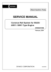
EVT (Electronic Variable Timer)
Electronic Variable Timer calculates the basic injection timing based on the engine load condition (rack position)
and engine revolution, and determines the target injection timing by adjusting it using the information from each
sensor.
It also detects the actual injection timing based on the phase difference between the N-TDC sensor and the timing
sensor, activates the timing control in accordance with the target injection timing, and controls the injection timing by
moving the timer hydraulically.
Engine revolution
Engine load
Determination
of the injection
timing
Signal input
• Water temp.
• Switch condition
signals etc.
Control unit
Target injection timing
Adjustment
Actual injection
timing
Recognition
Comparison
of the actual
injection
timing
N-TDC sensor
Timing
sensor
Timing control valve
driver
Bypass pipe
P
R
Timing control valve
Oil pump
Timer
EMISSION AND ELECTRICAL DIAGNOSIS 6E-13
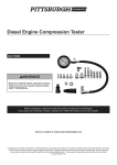
Engine ECU Wiring Diagram
6E-14 EMISSION AND ELECTRICAL DIAGNOSIS
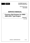
Component location
Engine ECU
Engine
EMISSION AND ELECTRICAL DIAGNOSIS 6E-15
HARNESS LOCATION
Vehicle Harness
ECU
A
ECU HARNESS
DUCT
CONNECTOR BOX
DASH PANEL
FOOT DUCT
A
ECU HARNESS
6E-16 EMISSION AND ELECTRICAL DIAGNOSIS
Engine ECU Terminal Assignment
130
105
115
1.2
30
85
transtron
10 9 8 7 6
Hybrid
I/O
connector
22&18P
22 side
5 4 3 2 1
4 3 2 1
22 21 20 19 18 17 16 15 14 13 12 11
18 17 16 15 14 13 12 11 10 9
22pin connector
18pin connector
No
A-1
A-2
A-3
A-4
A-5
A-6
A-7
A-8
A-9
A-10
A-11
A-12
Name
RACK SIG.
WATER TEMP +
NC
TDC SIG.
TIMING SIG.
DIAG.
NC
NC
NC
DDS-3
RACK +
A-13
WATER TEMP −
NC
TDC GND
TIMING GND
NC
NC
MEMORY CLEAR
TACHO OUT
NC
TECH 2
A-14
A-15
A-16
A-17
A-18
A-19
A-20
A-21
A-22
8 7 6 5
RACK −
Hybrid
I/O
connector
22&18P
18 side
No
B-1
B-2
B-3
B-4
B-5
B-6
B-7
B-8
B-9
B-10
B-11
B-12
Name
NC
NC
NC
NC
TCV RETURN
TCV PUMP
TCV PUMP +
VB
CASE GND
GND
NC
NC
B-13
NC
B-14
B-15
B-16
B-17
B-18
INDICATOR LAMP
NC
NC
TCV RETURN +
GND
EMISSION AND ELECTRICAL DIAGNOSIS 6E-17
DIAGNOSTIC PROCEDURE
Diagnostic procedure
Note
Take notes of present Diagnostic trouble code (DTC) during diagnosis, especially when multiple DTC are present.
Even though DTC can be cleared, diagnose related area in the system. Because DTC means there is or was some
failure, the failure may happen later.
Short
is
.
not be duplicated if engine
6E-18 EMISSION AND ELECTRICAL DIAGNOSIS
Self-diagnosis functions
Memorization of self-diagnosis code
The self-diagnosis code indicated will be memorized in EEPROM within ECU.
Accordingly even if the starter switch turns off or the ECU is removed from the vehicle, the memorized selfdiagnosis code will not be eliminated.
Memory clear for EVT
The memory is not cleared, however, by removing the battery.
The DTC codes of the ECU on the EVT are not cleared but maintained in the memory when the power is
turned off or the battery is removed off the body.
Confirm DTC code for dealer mode
Diagnosis code is detected by flashing W/L.
* Unless an elimination procedure is taken the self-diagnosis code will remain in memory. (the memory will be
eliminated only by a memory clear connector.)
Method to confirm the self-diagnosis code (dealer mode)
The self-diagnosis code can be read from the way the indicator lamp flashes.(service engine soon)
Reading self-diagnosis code from the flashing of the indicator lamp.
Detect DTC by Warning Lamp (W/L)
Operation
Connect Diagnosis connector, then W/L starts to flash. Flashing signal gives DTC code. Refer to the ‘how to read
DTC’.
of
*Inside
cover area.
PA type
1pin plug
connector(W)
Display
Engine revolution=0 → displays present code and history code
Engine revolution≠0 → displays present code only
Note: If no failure occurs or no history code is stored, '001' code flashes.
EMISSION AND ELECTRICAL DIAGNOSIS 6E-19
DTC clear procedure
1.
2.
3.
4.
5.
6.
Check if the memory connector is off.
Turn starter switch off, and turn starter switch on.
Connect memory clear switch on for 1 sec.
Disconnect memory connector after step 3, then memory is cleared for 0.4 sec after disconnected.
Turn starter switch off, and on. Check DTC is cleared. If DTC still exists, repeat step 1 through step 4.
Turn starter switch off and finish this process.
Memory clear switch position
of
*Inside
cover area.
PA type
1pin plug
connector(L)
How to read DTC
Three different flashing digits indicate a number is started from three-digits number, two different flashing digits
indicate a number is started from two-digit number in order. Identify DTC from the flashing number.
When multiple DTC are present, one DTC repeats three times and then turns to the next DTC.
6E-20 EMISSION AND ELECTRICAL DIAGNOSIS
The check procedure of non DTC failure (user mode)
When diagnosis sw is OFF, W/L on indicates the system failure.
There are three different ways of W/L indication.
1. No warning light (W/L) on ………. ‘-’ refer to DTC list
DTC is recorded, but no W/L on.
2. Conditionally W/L on ………. ‘ ’ refer to DTC list
In addition to DTC triggers, condition lasts more than 20 sec at less than 600 rpm (Ne) engine revolution,
then W/L lights ON.
3. Always W/L on ……….‘ ’ refer to DTC list
When DTC triggers, W/L always lights on.
Note: W/L indicates the following in case of no failure.
Ne=0 ………. light on
Ne≠0 ………. light off
Cancellation of DTC
When DTC is triggered, perform back-up mode.
One type of DTCs is canceled even during back-up mode, if it is detected failure is no more. The other type of
DTCs is not canceled until ECU is reset. First type of DTC means no damage to engine even for driving, second
DTC means engine damage may occur by driving.
EMISSION AND ELECTRICAL DIAGNOSIS 6E-21
Diagnosis Trouble Code (DTC) list
6HH1 EVT
DTC
Items
33 Memory(RAM)
543 Excessive high
engine revolution
10 Rack sensor
15
14
18
12
23
01
DTC
Failure description
Memory(RAM) error
More than 3770 rpm
Open or short eng. rpm
less than 1200 rpm
sensor voltage less than
*2
Open or short sensor
voltage more than *3
TDC sensor
Starter SW ON then no
pulse
Timing sensor
Starter SW ON then no
pulse
Timing Control Valve Open or short valve
voltage less than 0.8V at
the pump side
Open or short valve
voltage less than 0.8V at
the return side
Timer Feed Back
Difference of target and
actual for pre-stroke
angle is more than 3 deg
CA See *4
Coolant temperature Open or short sensor
sensor
voltage more than 4.8V
or sensor voltage less
than 0.1V
Normal
DTC cancel condition
Back-up
Detection time
DATA
DTC cancellation
TICS
Back up mode
Regular mode
No
No
None
0.5sec
None
None
30 sec
Rack position is
calculated by eng. rpm
Regular mode
No
1sec
None
Back up mode
No
1sec
None
Regular mode
No
1sec
None
Regular mode
Yes
30sec
None
Regular mode
Yes
3sec
Coolant temp = 80 °C
Regular mode
Yes
Back up mode
Regular mode
Yes
No back up mode
10sec
1sec
Diagnosis lamp display
Diag SW open (user)
Remark
Diag SW short (dealer)
Engine model
Reference page
33 None
None
-
None
48
543 None
None
5·4·3
DTC store only
No back-up
49
None
1·0
None
50
1·5
None
No DTC store
53
10 Determine at the
engine rpm failed
sensor voltage
become less than *2
detect at only the
engine rpm failed at
more than 1200 rpm
15 TDC sensor on
14 Timing sensor on
18 None
1·4
None
12 None
23 Sensor (resistance
input) voltage is less
than 4.8V and more
than 0.1V
1 Normal
None
57
1·81
None
61
1·2
None
64
2·3
None
67
0·1DTC
Diag lamp is on
-
-
6E-22 EMISSION AND ELECTRICAL DIAGNOSIS
Note
1. User mode display is as follows;
2.
3.
4.
5.
6.
7.
8.
: less than 600 rpm and last more than for 20 sec
: light on continuously
: no light on
Rack sensor output (high side) diagnosis voltages are different among engines; 6HH1 ........ 3.3V
Rack sensor output (low side) diagnosis voltage..................................................................... 0.7V
Pre-stroke angle (unit: deg) equivalent to ±3 deg CA is different ......................................... 8.7deg
For +3 deg CA difference between target and actual angle, it turns on always.
For -3 deg CA difference between target and actual angle, it does not turn on.
The following condition is not detected as failure.
Pre-stroke sensor was failure already.
Pre-stroke learning error is detected.
DTCs other than code 33 is not detected as less than 18 volts.
DTC code 543 is displayed by manual operation only.
When Using Tech 2, DTC code 54 is displayed.
EMISSION AND ELECTRICAL DIAGNOSIS 6E-23
CONNECTOR INSPECTING PROCEDURE
Connector inspecting procedure
6E-24 EMISSION AND ELECTRICAL DIAGNOSIS
1. WHITE SMOKE (EXCESSIVE)
White smoke excessive
Is system check done?
NO
Do system check.
YES
Check engine oil.
Is oil used normal
and clean?
NO
Replace it with normal one.
YES
Check fuel.
Is fuel used
normal and free of mixed
water or gasoline?
NO
Replace it with normal one.
YES
Check injection timing.
Is timing normal?
NO
Adjust injection timing.
YES
Check N-TDC sensor, timing
sensor, water temp. sensor.
(Refer to trouble codes)
Are sensor unit and
circuits normal?
YES
Check installation condition of
injection pump.
To (A)
NO
Repair or replace sensor unit
and circuits.
EMISSION AND ELECTRICAL DIAGNOSIS 6E-25
(A)
Is installation condition
normal?
NO
Adjust pump installation
position appropriately.
YES
Check engine condition.
NO
Is exhaust gas normal?
YES
Check and repair engine.
. Compression pressure
. Piston
. Piston ring
. Coolant leakage
. Gasket
Make a check of repairs.
End. Return to diagnostic
procedure if necessary.
NOTE 1:
The condition of the system in which the malfunction has occurred should be checked by making
comparisons between the vehicle ECU and the checking ECU.
6E-26 EMISSION AND ELECTRICAL DIAGNOSIS
2. LACK OF POWER
Insufficient output or poor
responsiveness
Def.: Engine output is lower
than expected.
Even pressing down
accelerator pedal halfway
does not increase speed.
Poor acceleration.
Is system check done?
NO
Do system check.
YES
Is visual inspection done?
NO
Do visual inspection.
YES
Check air cleaner.
Is air cleaner
free of clog and clean
and normal?
NO
Clean or replace air cleaner.
YES
Drive with driver's condition.
Is driving
condition normal?
Make a check of repairs.
NO
Check installation condition
of engine control cable.
Is installation
condition normal?
NO
Adjust engine control cable.
YES
End
Drive with driver's condition.
Is driving
condition normal?
Make a check of repairs.
End
To (A)
EMISSION AND ELECTRICAL DIAGNOSIS 6E-27
(A)
Check exhaust gas system for
clogging and damages, and
silencer for internal defects.
Is exhaust gas
system normal?
NO
Repair it.
YES
Drive with driver’s condition.
Is driving condition
normal?
NO
YES
Make a check of repairs.
End.
Check brake and auxiliary
brake system.
Are brake and
auxiliary brake system
normal?
NO
Repair them.
YES
Drive with driver’s condition.
Is driving condition
normal?
NO
Check engine for compression
pressure, valve system, etc.,
and repair them if necessary.
YES
Make a check of repairs.
End. Return to diagnostic
procedure if necessary.
NOTE 1:
The condition of the system in which the malfunction has occurred should be checked by making
comparisons between the vehicle ECU and the checking ECU.
6E-28 EMISSION AND ELECTRICAL DIAGNOSIS
3. TACHOMETER ABNORMALITY
Tachometer abnormal
Is system check done?
NO
Do system check.
YES
Check and diagnose meter.
Is meter normal?
NO
Repair or replace it.
YES
Check circuit between ECU
and meter for continuity,
breakage and short-circuit.
Is circuit normal?
NO
Repair it.
YES
Check to see whether
tachometer operates.
Is meter normal?
NO
Replace ECU.
YES
Make a check of repairs.
End. Return to diagnostic
procedure if necessary.
NOTE 1:
Check continuity among each terminal 17 - 16 , 16 - 2 , 2 -
A-20
. following circuit diagram on next page.
EMISSION AND ELECTRICAL DIAGNOSIS 6E-29
Female
SDL
14 PIN
SMJ
84 PIN
17
16
22 PIN
2
A20
Tachometer
Connector B
Connector A
ECU
CONTROL
UNIT;EVT
NOTE 2: The condition of the system in which the malfunction has occurred should be checked by making
comparisons between the vehicle ECU and the checking ECU.
FRONT
METER
Connector A
Connector B
CAB
ECU
Female side
Female side
6E-30 EMISSION AND ELECTRICAL DIAGNOSIS
4. W/L LAMP (DIAG LAMP) MALFUNCTION
(1) The W/L lamp remains lit.
Fuse20
Refer to the connector
SMJ 84 PIN
B8
Connector A
15
6
9
B14
ECU
7
45
Connector B
7 6 5 4
3 2 1
15 14 13 12 11 10 9 8
Fuse11
Refer to DTC 23 section
SDL 14 PIN
B10 B18 B9
Refer to DTC 23 section
SDL 14 PIN
3
4
Meter terminal A connector
12
13
17
1 2 3 4 5 6 7 8 9 10 11
12 13 14 15 16 17 18 19 20 21 22
Joint Connector
Refer to DTC 23 section
SDL 22 PIN
18
Connector C
EMISSION AND ELECTRICAL DIAGNOSIS 6E-31
(2) The W/L lamp will not come on even when the starter SW is on.
W/L lamp check
(it does not blink)
Remove diagnosis switch.
Set starter switch to OFF.
Remove ECU.
Set starter switch to ON.
1
NO
Is lamp lit?
YES
Set starter switch to OFF.
Check lamp circuit
(between lamp and ECU)
for continuity, breakage
and short-circuit.
NO
Is circuit normal?
Repair lamp circuit
(between lamp and ECU).
YES
Set starter switch to ON.
Is lamp out?
NO
Repair or replace meter.
Repair circuit between
meter and fuse.
2
Set starter switch to OFF.
Check circuit of diagnosis
switch for continuity,
breakage and short-circuit.
Check circuit between
ECU and diagnosis switch.
Check circuit between
diagnosis switch and
ground point.
NO
YES
Is circuit normal?
Set starter switch to
OFF and connect ECU.
YES
Set starter switch to
ON and connect diagnosis
switch.
Is lamp out?
Repair circuit of
diagnosis switch.
Set starter switch to ON
and connect diagnosis
switch.
NO
Is lamp blinking?
YES
YES
Check trouble code.
3
Is trouble code [1]?
YES
Make a check of repairs.
End. Return to diagnostic
procedure if necessary.
NO
Refer to corresponding
trouble code.
NO
Set starter switch to
OFF and replace ECU.
6E-32 EMISSION AND ELECTRICAL DIAGNOSIS
Refer to DTC 23 section SOL18 PIN
NOMAL OPEN
S1 PIN
Female Male
1
5
A6
ECU
Connector E
Connector D
Refer to DTC 23 section SOL22 PIN*
1 2 3 4 5 6 7 8 9 10 11
12 13 14 15 16 17 18 19 20 21 22
15
17
18
Connector C
SDL22P
Joint Connector
*Encircled numbers indicate pin numbers.
Joint Connector
Connector C
FRONT
Connector E
Connector D
Joint
Connector
CAB
ECU
3rd Cross member
Battery
EMISSION AND ELECTRICAL DIAGNOSIS 6E-33
Tech 2 Overview and applicable model
This service manual is applicable to the model in the following table.
Vehicle Type
Medium Duty
Model
6HH1 (F-Series)
Model Year
'00 MY
Purpose:
This manual is prepared for engine diagnoses and system checks using Tech 2.
Tech 2 Operation Manual
Diagnosis Strategy-Based Diagnostics
Strategy-Based Diagnostics
The strategy-based diagnostic is a uniform approach to repair all Electrical/Electronic (E/E) systems. The
diagnostic flow can always be used to resolve an E/E system problem and is a starting point when repairs are
necessary. The following steps will instruct the technician how to proceed with a diagnosis:
1. Verify the customer complaint.
To verify the customer complaint, the technician should know the normal operation of the system. = not present
(History)
2.
•
•
•
•
Perform preliminary checks.
Conduct a thorough visual inspection.
Review the service history.
Detect unusual sounds or odors.
Gather diagnostic trouble code information to achieve an effective repair. =Intermittent
3. Check bulletins and other service information. System checks contain information on a system that may not be
supported by one or more DTCs. System checks verify proper operation of the system. This will lead the
technician in an organized approach to diagnostics. = Preset
Reading Diagnostic Trouble Codes Using the Tech 2 Scan Tool
The procedure for reading diagnostic trouble code(s) is to use a diagnostic Scan Tool. When reading DTC(s),
follow instructions supplied by the tool manufacturer.
Clearing Diagnostic Trouble Codes.
IMPORTANT: Do not clear DTCs unless directed to do so by the service information provided for each diagnostic
procedure. When DTC(s) is cleared, the Failure Record data that may help diagnose and intermittent fault will also
be erased from the memory.
To clear Diagnostic Trouble Codes (DTCs), use the diagnostic Scan Tool "clear information" or "Programming"
function. When the DTC(s) is cleared the following instructions are supplied by the tool manufacturer.
Tech 2 Features
1. Tech 2 is a 12 volts system. Do not apply 24 volts.
NOTE: Install the Tech 2 Adapter and supply voltage is 12 volts for Tech 2.
2. After connecting and/or installing the Vehicle Communication Interface (VCI) module, PCMCIA card and DLC
connector to the Tech 2, connect the tool to the vehicle DLC.
3. Make sure the Tech 2 is powered OFF when removing or installing the PCMCIA card.
4. The PCMCIA card has a capacity of 10 Megabytes.
5. The Tech 2 has two snapshots.
6. The PCMCIA card is sensitive to magnetism and static electricity, so care should be taken in the handling of the
card.
6E-34 EMISSION AND ELECTRICAL DIAGNOSIS
7. The Tech 2 can plot a graph when replaying snapshot.
8. Always return to the Main Menu by pressing the EXIT key several times before shutting down.
9. To clear Diagnostic Trouble codes (DTCs), open Application Menu and press "F1: Clear DTC info".
NOTE: The RS232 Loop back connector is only to be used for diagnosis of Tech 2.
Refer to users guide of the Tech 2.
To prevent system damage, the ignition key must be "OFF" when disconnecting or reconnecting battery
power.
EMISSION AND ELECTRICAL DIAGNOSIS 6E-35
Overview
Tech 2 is useful for engine diagnoses and system checks. Although trouble diagnosis can be performed without
Tech 2, using Tech 2 will increase efficiency.
Tech 2 is a portable, compact and light tester. Connected with the self-test connector of the vehicle, Tech 2
performs various diagnoses and tests by communicating with ECM.
Tech 2
Names
(1) PCMCIA card
(2) DLC cable
(3) SAE 16/19 pin adapter
(4) Adapter cable
(5) Tech 2
Notes:
• Tech 2 requires power supply of 12 V.
• Be sure to use the adapter cable.
• ISB applicable vehicle model is equipped with a 24 V power supply.
• Be sure to turn the power OFF when removing and attaching PCMCIA card.
• Be sure to use a conversion adapter to comply with a 20-pin connector of DLC (vehicle equipment).
• Mount the adapter to DLC and connect Tech 2 to the adapter.
• Be sure to use the Tech 2 adapter.
6E-36 EMISSION AND ELECTRICAL DIAGNOSIS
Tech 2 adapter
Legend
(1) Tech 2 adapter
Note: Be sure to set the TXD switch to the right side as illustrated and select the system selector
switch to the #3 position.
(2) Adapter cable
*1. DLC cable
*2. Adapter cable
*3. Connector for I/E
EMISSION AND ELECTRICAL DIAGNOSIS 6E-37
Location of DLC
DLC 20 Pin 10
1
20
11
Attaching Tech 2
1 Insert the ISUZU 98 system PCMCIA card into the Tech 2 main body.
2 Connect the adapter to the DLC cable.
3 Attach the DLC cable to the Tech 2 main body.
4 Check that the ignition key is in the OFF position.
5 Connect the adapter of Tech 2 to the diagnosis connector (black) of the vehicle.
6 Turn the ignition key ON and push the "PWR" key of Tech 2.
7 Check the display of Tech 2.
6E-38 EMISSION AND ELECTRICAL DIAGNOSIS
DLC connection
DLC 20 Pin 10
1
20
11
Note:
Be sure to remove or attach the PCMCIA card when the power of Tech 2 is OFF.
20 Pins Connector Pin assignment
10
1
20
11
Tech
2
Press [ENTER] to continue.
Software Version: x.xxx
Isuzu 1998 - 2000
Pin No.3 = Power supply
Pin No.4 = Tech 2 signal (TXD)
Pin No.12 = Tech 2 signal (RXD)
Pin No.13 = Ground earth
Operation of Tech 2
1. Check the initial display appears.
EMISSION AND ELECTRICAL DIAGNOSIS 6E-39
2. Press [ENTER].
The Main menu appears.
Main Menu
F0: Diagnostics
F1: Service Programming System (SPS)
F2: View Capture Data
F3: Tool Options
F4: Download / Upload Help
3. Select [F0] and press [ENTER].
The Vehicle Identification display to select Model
appears.
Vehicle Identification
Select one of the following
Model Year(s)
(Y) 2000
(X) 1999
(W) 1998
1/3
(Y) 2000
4. Select Applicable Model Year.
For instance "2000" and press [ENTER].
Vehicle Identification
Select one of the following
Vehicle Type (s)
(UB) Trooper, Bighorn
(UE) Rodeo / Amigo, Wizard/MU
(UG) V-Cross
(UC) Frontier, LAO-Rodeo
(TF) LUV
(TB) Panther
(N∗) ELF, NPR, NQR
(C∗,E∗,L∗,F∗) Heavy, Medium Duty
(C∗,E∗,L∗,F∗) Heavy, Medium Duty
8/8
System Selection Menu
(Y) 2000 (C ,E ,L ,F ) Heavy, Medium Du
5. Select [Heavy, Medium Duty] and press [ENTER].
The System Selection Menu appears.
F0: Engine
F1: Transmission
F2: Chassis
F3: Body
6. Select [F0] and press [ENTER].
The Vehicle Identification display to select Engine
appears.
Vehicle Identification
Select one of the following
Engine
(IE) 6HK1-X (Common Rail) Taiwan
(IE) 6HH1 / 6HK1-TC (China)
(IE) 6HH1 (EXP)
(IE) 6SD1-TC
(IE) 6HE1-TC
(IE) 6WA1-TC
(IE) 6WG1-TC
(IE) 8PE1 (SKW)
Other
(IE) 6HH1 / 6HK1-TC (China)
2/9
6E-40 EMISSION AND ELECTRICAL DIAGNOSIS
System Indentification
(C∗,E∗,L∗,F∗) Heavy, Medium Duty
Engine / (IE) 6HH1 / 6HK1-TC (China)
7. Select engine model (6HH1/6HK1-TC (China)) and
press [ENTER].
The System Identification display to turn on ignition
appears.
Turn On Ignition!
Confirm
System Indentification
(C∗,E∗,L∗,F∗) Heavy, Medium Duty
Engine / (IE) 6HH1 / 6HK1-TC (China)
8. Turn on the ignition and press [Confirm].
The System identification display to enter ROM ID.
number appears.
Enter the ROM Identification number then confirm it.
ROM Identification 6HH1:22116040
6HK1-TC (China):22216040
Confirm
9. After engine display appears, select [F0] and press
[ENTER].
Engine
F0: Diagnostic Trouble Codes
F1: Data Display
F2: Snapshot
Diagnostic Trouble Codes
10. Select [F1] and press [ENTER].
The Diagnostic Trouble Codes display appears.
F0: Read DTC Info Ordered By Priority
F1: Clear DTC Information
Clear DTC Information
(C∗,E∗,L∗,F∗) Heavy, Medium Duty
Engine : (IE) 6HH1 / 6HK1-TC (China)
Do you want to clear DTCs? (Yes / No)
NO
YES
11. Select [F1] and press [ENTER].
The Clear DTC Information display appears.
Press [Yes] and the DTC number is cleared.
EMISSION AND ELECTRICAL DIAGNOSIS 6E-41
12. The Clear DTC Information display appears.
Press [Continue] and then return to the Diagnostic
Trouble Codes display.
Clear DTC Information
Clear DTC Information Successful
Continue
Clear DTC Information
(C ,E ,L ,F ) Heavy, Medium Duty
Engine : (IE) 6HH1 / 6HK1-TC(China)
13. After the DTC number is cleared, check and confirm
the DTC number.
Please Check DTCs.
Confirm
14. Select the Data Display.
Data Display
Clear Memory Switch
Off
Diagnostic Switch
Off
Actual Rack Voltage
Corrected Rack Sensor V
Engine Speed (RPM)
Target Timing Advance A
Actual Timing Advance A
Engine Coolant Temperat
Clear Memory Switch
Select
DTC
Items
Quick
Snapshot
Snapshot Options
Trigger Type : Manual Trigger
F0 : Manual Trigger
F1 : Any Code
F2 : Single Code
Trigger Point : Center
F4 : Beginning
F5 : Center
F6 : End
Record
Snapshot
Review
Data
1.65 V
1.6 V
363 Miles
7
0
56 F
1 / 8
More
15. Select the Snapshot Options display.
6E-42 EMISSION AND ELECTRICAL DIAGNOSIS
Flow Chart for Snapshot relay (Plotting Graph)
Press the enter-key in the initial display.
Select "VIEW CAPTURE DATA"
If snapshot options are displayed, decide a
trigger type, and select "REVIEW DATA".
When the data triggered by vehicle is
displayed, select the data.
(Plural display of data depending on the
number of times of triggering.)
Data is displayed on the screen.
To see the graph, select "PLOT" in the
lower part of the monitor screen.
Changed to the item selection screen,
push the enter key up to three times. And
select "ACCEPT" under screen.
The graph is displayed on the screen.
EMISSION AND ELECTRICAL DIAGNOSIS 6E-43
Plotting Graph Flow Chart (Plotting graph after obtaining vehicle information)
Procedure Based on Data Display
Procedure Based on Trigger Type Decision
After confirming FLOW "MAIN MENU
DIAGNOSIS" -ID, select "DATA DISPLAY" from
APPLICATION MENU.
After confirming FLOW "MAIN MENU
DIAGNOSIS" -ID, select "SNAP SHOT" from
APPLICATION MENU.
After the display of vehicle data, select "QUICK
SNAPSHOT" in the lower part of the monitor
screen.
Select when the items have been displayed.
After the display of snapshot option, decide a
trigger type, and select "RECORD
SNAPSHOT".
After the lapse of some time, push "EXIT"
button.
If (STANDBY) blinks, at the upper right of the
screen, select "TRIGGER".
Confirm the trigger type.
If "CONTINUE" is displayed in the lower part of
the monitor screen after the screen is changed,
select the data.
If "PLOT" is displayed in the lower part of the
monitor screen, select "PLOT".
When changed to the item selecting screen,
push the enter key in accordance with the
items up to three items and select "ACCEPT" in
the lower part of the monitor screen.
The graph is displayed on the screen.
6E-44 EMISSION AND ELECTRICAL DIAGNOSIS
Troubleshooting
System Diagnosis
System diagnosis
The system diagnosis is used to repair the electrical/electronic system. Troubles of the E/E system are different
from general vehicle troubles and they can be classified as follows.
1. Initial state trouble
• This trouble occurs only once and persists for a short time. Therefore, customers are apt to overlook it. In this
state, the customer's complaint is not clear and servicemen cannot re-produce the trouble. ECU, however, may
memorize the trouble.
= Not-present state (past trouble)
2. Middle state trouble
• This trouble occurs intermittently but persists for a short time. Under a certain condition, this trouble occurs
without exception. The trouble the customer complains is clear but the cause is not. Servicemen can re-produce
the trouble if they can identify the condition.
=Intermittent state (intermittent trouble)
3. Advanced state trouble
• This trouble occurs constantly and persists. Customer's complaint is practical and clear. Servicemen can reproduce the trouble. There may be, however, two or more causes of the trouble.
=Present state (current trouble)
Use the diagnostic flow chart to repair the E/E system troubles. The flow chart is also used as a start point. The
procedure of diagnosis is described below.
1. Examine the customer's complaint.
• Servicemen must be well acquainted with the normal operation of the system.
• It is required to examine the condition of the trouble
2.
•
•
•
•
Perform a preliminary check.
Perform a total visual inspection.
Review the maintenance record.
Detect abnormal sound or odor.
Collect the diagnostic trouble code information for a more effective repair.
3. Examine reports and other service information.
• Videos and newsletters are included.
4. Refer to the service information (manual).
• The "System Check" includes information that is not supported by one or more DTC (Diagnostic Trouble Code).
The System Check monitors the normal operation of the system, providing servicemen with a systematic
diagnosis.
When DTC (Diagnostic Trouble Code) is memorized
Perform an effective repair according to the specified DTC chart.
When there is no DTC
Select a symptom from the diagnostic table classified by symptom. Perform a repair according to the diagnostic
procedure. It is possible for servicemen to refer to constituent parts/system checks available with the System
Check.
EMISSION AND ELECTRICAL DIAGNOSIS 6E-45
When there is no relevant symptom
1. Analyze the customer's complaint.
2. Develop a diagnostic strategy.
3. Make use of the wiring diagrams and operation principles.
Ask for technical supports when the trouble resembles a recorded case. Combine the technical knowledge of
servicemen with available service information effectively.
In case of intermittent troubles
Troubles that do not occur necessarily at all times are referred to as intermittent troubles. To repair the intermittent
trouble, perform the following procedure.
1. Examine the vehicle automatic records (frozen frame data) using the past DTC, DTC mode and scanning tool
(Tech 2).
2. Evaluate the symptom and condition of the customer's complaint.
3. Examine the constituent parts of the circuits and electrical system using the check sheet or other means.
4. Follow the instructions of the intermittent trouble diagnosis described in the service document.
Most scanning tools such as Tech 2 are equipped with a data tracking ability useful in detection of the intermittent
trouble.
When a trouble is not detected
This is when the vehicle is judged in the normal operation. Despite the customer's complaint, the vehicle can be in a
normal condition. Compare the customer's complaint with the condition of a normal vehicle. The trouble may be one
of the intermittent troubles. Before returning the vehicle to the customer, examine the complaint under the condition
the customer specifies.
1. Examine the customer's complaint.
If the trouble cannot be detected or identified, it is necessary to evaluate the trouble again. The complaint must
be examined again. The vehicle may prove normal as well as the trouble may prove intermittent.
2. Repair and check
After the cause is identified, it is necessary to repair the trouble. Check the trouble is repaired and demonstrate
the normal operation of the vehicle. This procedure includes road tests or other checks to prove the trouble is
repaired under the following conditions.
•
•
Test and check the vehicle under the condition specified by the customer.
When DTC has been issued, re-produce the condition where the DTC appeared using the scanning tool (Tech
2) according to the vehicle automatic record, and check the vehicle for the normal operation.
Checking the repairs
Checking the repairs is more comprehensive for vehicles using the IE system trouble diagnosis.
IMPORTANCE
Servicemen should perform the following procedure after the repair. Otherwise, unnecessary repairs may be
undertaken.
1.
2.
3.
4.
Review the trouble record of the diagnosed DTC and record it.
Clear the DTC.
Run the vehicle under the condition specified in the trouble record.
Examine the status information of the diagnosed DTC until the diagnostic test related to the DTC is carried out.
NOTE
One of the necessary DTC status information is about the DTC setting condition. The time taken from the
vehicle start up to the recognition of the DTC and the condition are important. As a guide, perform the DTC
diagnostic test after warming up the vehicle sufficiently (water temperature; 70 °C or higher). If the vehicle
is tested under a different condition with wrong time interval, the customer's complaint may occur again.
6E-46 EMISSION AND ELECTRICAL DIAGNOSIS
General Service Information
Problems of serviceability
Non-OEM parts
Every trouble diagnosis is designed to operate with OEM parts. If sensors or switches available on the market are
attached, the IE lamp ("CHECK ENGINE" lamp) will light due to diagnostic errors. Electronic equipment, such as
radio equipment, stereo system, theft-lock system, available on the market may radiate interference noises (EMI) to
the control system, if they are installed inappropriately. This will lead to the occurrence of wrong sensor information
and illumination of the IE lamp ("CHECK ENGINE" lamp).
Poor maintenance of the vehicle
The IE trouble diagnosis is so sensitive that the IE warning lamp ("CHECKING ENGINE" lamp) may light due to
poor maintenance of the vehicle. Lack of oil replacement, clogging of the oil filter and fuel filter due to inappropriate
viscosity of the oil, and the subsidence attached to the crankcase may cause vehicle malfunctions that were not
detected before the IE system trouble diagnosis. Although a poor maintenance of the vehicle is not classified into
the "Troubles not related to the vehicle", observe the maintenance schedule of the vehicle more strictly because the
trouble diagnosis is very sensitive.
Troubles of the related system
Most system trouble diagnoses will stop functioning when ECU detects troubles of the related system or constituent
parts.
Visual Inspection of the Engine
When performing the diagnosis procedure, inspect the engine visually with special care. The visual inspection may
resolve the trouble without unnecessary procedure. Perform the visual Inspection according to the following
guideline.
•
•
•
Check every piping hose for punch holes, cuts, disconnection and appropriate piping.
Check the hoses hidden by other constituent parts.
Check every wire of the engine for appropriate connection, burns and abrasions. Check also that the wire is not
pressed excessively, not touched with edges, or not connected to the hot exhaust manifold or pipes.
Basic knowledge about the required tools
CAUTION
The basic knowledge about the power train is necessary for the diagnostic procedure. Lack of this
knowledge may cause diagnostic error and damages to the constituent parts of the power train.
Servicemen without the knowledge must not attempt to diagnose the trouble related to the power train.
The basic understanding of Tech 2 is required for an effective use of this chapter in the service manual.
EMISSION AND ELECTRICAL DIAGNOSIS 6E-47
DTC Code:
DTC
33
54
10
15
14
18
12
23
Note:
:
:
-:
DESCRIPTION
Internal Control Module Random Access Memory(RAM)
Engine Speed Too High
Rack Sensor Open Or Short Circuit
TDC Sensor Error
Timing Sensor Error
TCV Open Or Short Circuit
Timer Feedback Error
Engine Coolant Temperature Open Or Short Circuit
SERVICE
ENGINE SOON
Note1
-
-
When diagnosis switch opens (user mode), trouble indication sign is shown as follows:
Indicator turns on when less than 600 rpm last for 20 seconds.
Indicator continuously turns on.
Indicator does not turn on.
Note1: DTC code number 543 is displayed with manual flashing operation.
6E-48 EMISSION AND ELECTRICAL DIAGNOSIS
DTC 33 Memory (RAM) error
STEP
1
ACTION
Replace ECU
YES
Solved
NO
NOTE: Proper diagnosis can not be made due to malfunction of ECU. Check ECU again for malfunction
after replacement.
EMISSION AND ELECTRICAL DIAGNOSIS 6E-49
DTC 54 Excessive high engine revolution error
Tech 2 operation
STEP
1
2
ACTION
1. Check high engine revolution error.
2. Check diagnosis error?
YES
Go to Step 2.
1. Set Tech 2 to IE and read W/L flashing.
Procedure
2. Was DTC code 10 displayed?
DTC code 10
Go to Step 4.
3
1. Inspect engine unit, clutch and related parts for
abnormality.
2. Starter SW on.
3. After holding down memory clear switch for at least one
second, release it.
4. Once set Tech 2 to OFF and then set it to read DTC.
5. Confirm if DTC is cleared.
4
End.
Solved.
Return to diagnostic procedure if necessary.
Note: DTC code number 543 is displayed with manual flashing operation.
NO
Check
diagnostic
error.
Go to Step 3.
Go back to
Step 2.
Go back to
Step 3.
6E-50 EMISSION AND ELECTRICAL DIAGNOSIS
DTC 10 Rack sensor
Rack Sensor Connector
Rack sensor connector terminal assignment
Injection pump side connector
(Location in connector box)
Terminal
Signal Name
NO.
1
+5V
2
SIG
3
GND
Color
of wire
R
W
B
EMISSION AND ELECTRICAL DIAGNOSIS 6E-51
DTC 10 Rack sensor error
Manual flashing operation
STEP
ACTION
1
1. Check rack sensor error.
2. Check diagnosis error?
2
3
4
5
6
7
1. Starter SW off.
2. Open connector box.
3. Disconnect rack sensor connector and harness
connector of cab.
4. Disconnect wire harness from engine ECU.
5. Inspect if rack sensor circuit (+5), (SIG) and (GND) have
short circuit.
6. Check continuity, short circuit and snapping wire of rack
sensor between connector box and engine ECU
connector.
7. Was circuit correct?
1. Connect wire harness to ECU.
2. Start SW on.
3. Measure output voltage at connector terminal at ECU
harness.
4. Was voltage 4.75 to 5.25V?
1. Replace rack sensor.
2. Replace injection pump.
3. Connect all harness to engine.
4. Clear DTC code.
5. Was DTC cleared?
1. Make sure of repair procedure.
2. Connect Scan tool and refer to lack voltage of monitor.
3. Was resistance correct?
1. Starter SW on.
2. Run engine.
3. Was DTC 10 displayed?
End.
Return to diagnostic procedure if necessary.
YES
Go to Step 2.
Go to Step 3.
NO
Check
diagnostic
error.
Repair circuit.
Go to Step 4.
Replace ECU.
Go to Step 5.
Go back to
Step 3.
Go to Step 6.
Go back to
Step 4.
Go to Step 7.
Go back to
Step 5.
Solved
Go back to
Step 1.
6E-52 EMISSION AND ELECTRICAL DIAGNOSIS
Tech 2 operation
STEP
ACTION
1
1. Check rack sensor error.
2. Check diagnosis error?
2
3
4
5
6
1. Starter SW off.
2. Open connector box.
3. Disconnect rack sensor connector and harness
connector of cab.
4. Disconnect wire harness from engine ECU.
5. Inspect if rack sensor circuit (+5), (SIG) and (GND) have
short circuit.
6. Check continuity, short circuit and snapping wire of rack
sensor between connector box and engine ECU
connector.
7. Was circuit correct?
1. Connect wire harness to ECU.
2. Starter SW on.
3. Measure output voltage at connector terminal at ECU
harness.
4. Was voltage 4.75 to 5.25V?
1. Replace rack sensor.
2. Replace injection pump.
3. Connect all harness to engine.
4. Run engine.
5. Set Tech 2 to read flickering condition of W/L.
1. Stop engine run.
2. Starter SW on.
3. After holding down memory clear switch for at least one
second, release it.
4. Once set Tech 2 to OFF and then set it to read DTC.
5. Confirm if DTC is cleared.
End.
Return to diagnostic procedure if necessary.
YES
Go to Step 2.
Go to Step 3.
NO
Check
diagnostic
error.
Repair circuit.
Go to Step 4.
Replace ECU.
Go to Step 5.
Go back to
Step 3.
Go to Step 6.
Go back to
Step 4.
Solved
Go back to
Step 1.
EMISSION AND ELECTRICAL DIAGNOSIS 6E-53
DTC 15 TDC sensor error
TDC Sensor Connector
To injection pump
SWP 3pin
1 2 3
1 2 3
Sub wire harness
3 2 1
(3pin)
Injection pump side connector
(Location in connector box)
Terminal
Signal Name
NO.
1
+5V
2
SIG
3
GND
Engine ECU Connector
Color
of wire
R
G
B
6E-54 EMISSION AND ELECTRICAL DIAGNOSIS
TDC sensor appearance, terminal assignment
To TDC sensor
TDC sensor appearance
3 2 1
(3pin)
TDC sensor side connector
(Located in connector box)
(3pin)
Terminal
Signal Name
NO.
1
GND
2
SIG
3
+5V
Measure TDC sensor resistance
Circuit tester (DMV)
Remove off vehicle harness
TDC sensor
Connect box
Measure resistance
between these
To TDC sensor
3 2 1
(3pin)
TDC sensor side connector
(Located in connector box)
Resistance
Connector
(3pin)
Inspection area
2 terminal
↔
2 terminal
↔
2 terminal
↔
1 terminal
↔
1 terminal
↔
3 terminal
↔
terminal
3 terminal
Body
3 terminal
Body
Body
1
Resistance
125.5 ± 17 [Ω]
∞
∞
∞
∞
∞
SIG
SIG
SIG
GND
GND
Shield
Remark
↔ GND
↔ Shield
↔ Body
↔ Shield
↔ Body
↔ Body
Wire
Color
B
G
R
EMISSION AND ELECTRICAL DIAGNOSIS 6E-55
DTC 15 TDC sensor error
Manual flashing operation
STEP
ACTION
1
1. Check TDC sensor error
2. Check diagnosis error?
2
3
4
5
6
7
8
1. Starter sw off.
2. Disconnect TDC sensor connector and harness
connector of cab.
3. Disconnect wire harness from engine ECU.
4. Inspect if TDC sensor circuit (+5), (SIG) and (GND) have
short circuit.
5. Check continuity, short circuit and snapping wire of TDC
sensor.
6. Was circuit correct?
1. Connect wire harness to ECU.
2. Start SW on.
3. Measure resistance of TDC sensor.
4. Was resistance correct?
1. Check installation of TDC sensor.
2. Check TDC sensor for damage.
3. Is there any failure?
1. Remove TDC sensor.
2. Make sure that there is magnetic force at the tip of TDC
sensor.
3. Was magnetic force available?
1. Check installation of sensing plate for injection pump for
TDC sensor.
2. Was sensing plate correct?
1. Replace ECU.
2. Clear DTC code.3. Make sure of repair procedure.
End.
Return to diagnostic procedure if necessary.
YES
Go to Step 2.
Go to Step 3.
Go to Step 4.
Go to Step 5.
Go to Step 6.
NO
Check
diagnostic
error.
Repair circuit.
Replace TDC
sensor.
Reinstall or
inspect the
TDC sensor.
Replace TDC
sensor .
Go to Step 7.
Replace
injection pump.
Go to Step 8.
Go back to
Step 6.
Go to Step 1.
Solved
6E-56 EMISSION AND ELECTRICAL DIAGNOSIS
Tech 2 operation
STEP
ACTION
1
1. Check TDC sensor error
2. Check diagnosis error?
2
3
4
5
6
7
8
1. Starter SW off.
2. Disconnect TDC sensor connector and harness
connector of cab.
3. Disconnect wire harness from engine ECU.
4. Inspect if TDC sensor circuit (+5), (SIG) and (GND) have
short circuit.
5. Check continuity, short circuit and snapping wire of TDC
sensor.
6. Was circuit correct?
1. Connect wire harness to ECU.
2. Start SW on.
3. Measure resistance of TDC sensor.
4. Was resistance correct?
1. Check installation of TDC sensor.
2. Check TDC sensor for damage.
3. Is there any failure?
1. Remove TDC sensor.
2. Make sure that there is magnetic force at the tip of TDC
sensor.
3. Was magnetic force available?
1. Replace TDC sensor.
2. Run engine.
3. Set Tech 2 to read flickering condition of W/L.
4. Was DTC 15 displayed?
1. Stop engine run.
2. Starter SW on.
3. After holding down memory clear switch for at least one
second, release it.
4. Once set Tech 2 to OFF and then set it to read DTC.
5. Confirm if DTC is cleared.
End.
Return to diagnostic procedure if necessary.
YES
Go to Step 2.
Go to Step 3.
NO
Check
diagnostic
error.
Repair circuit.
Go to Step 4.
Replace TDC
sensor.
Go to Step 5.
Reinstall or
inspect the
TDC sensor.
Replace TDC
sensor .
Go to Step 6.
Go to Step 7.
Replace
injection pump.
Go to Step 8.
Go back to
Step 6.
Solved. Go to
Step 1.
Go to Step 1.
EMISSION AND ELECTRICAL DIAGNOSIS 6E-57
DTC 14 Timing sensor error
Timing Sensor Connector
Engine ECU Connector
10 9 8 7 6
5 4 3 2 1
8 7 6 5
4 3 2 1
22 21 20 19 18 17 16 15 14 13 12 11
18 17 16 15 14 13 12 11 10 9
22pin connector
18pin connector
6E-58 EMISSION AND ELECTRICAL DIAGNOSIS
Timing sensor appearance, terminal assignment
To Timing sensor
Timing sensor appearance
3 2 1
(Black 3pin)
Timing sensor side connector
(Located in connector box)
(Black 3pin)
Terminal
Signal Name
NO.
1
GND
2
SIG
3
Shield
Measure Timing sensor resistance
Circuit tester (DMV)
Remove off vehicle harness
Timing sensor
Connect box
Measure resistance
between these
To Timing sensor
3 2 1
(Black 3pin)
Timing sensor side connector
(Located in connector box)
Resistance
Connector
(black 3pin)
Inspection area
2 terminal
↔
2 terminal
↔
2 terminal
↔
1 terminal
↔
1 terminal
↔
3 terminal
↔
terminal
3 terminal
Body
3 terminal
Body
Body
1
Resistance
2.1 ∼ 2.5 [kΩ]
∞
∞
∞
∞
∞
SIG
SIG
SIG
GND
GND
Shield
Remark
↔ GND
↔ Shield
↔ Body
↔ Shield
↔ Body
↔ Body
Wire
Color
B
Y
G
EMISSION AND ELECTRICAL DIAGNOSIS 6E-59
DTC 14 Timing sensor error
Manual flashing operation
STEP
ACTION
1
1. Check Timing sensor error
2. Check diagnosis error?
2
3
4
5
6
7
8
1. Starter SW off.
2. Disconnect Timing sensor connector and harness
connector of cab.
3. Disconnect wire harness from engine ECU.
4. Inspect if Timing sensor circuit (+5), (SIG) and (GND)
have short circuit.
5. Check continuity, short circuit and snapping wire of
Timing sensor.
6. Was circuit correct?
1. Connect wire harness to ECU.
2. Starter SW on.
3. Measure resistance of Timing sensor.
4. Was resistance correct?
1. Check installation of Timing sensor.
2. Inspect Timing sensor gap.
3. Was gap value less than the following?
less than 1mm.
1. Remove Timing sensor.
2. Make sure that there is magnetic force at the tip of TDC
sensor.
3. Was magnetic force available?
1. Check installation of sensing plate for injection pump for
Timing sensor.
2. Was sensing plate correct?
1. Replace ECU.
2. Clear DTC code.
3. Make sure of repair procedure.
End.
Return to diagnostic procedure if necessary.
YES
Go to Step 2.
Go to Step 3.
NO
Check
diagnostic
error.
Repair circuit.
Go to Step 4.
Replace
Timing sensor
sensor.
Go to Step 5.
Adjust gap
value.
Go to Step 6.
Replace
Timing sensor.
Go to Step 7.
Replace
injection pump.
Go to Step 8.
Go back to
Step 6.
Solved
Go to Step 1.
6E-60 EMISSION AND ELECTRICAL DIAGNOSIS
Tech 2 operation
STEP
ACTION
1
1. Check Timing sensor error
2. Check diagnosis error?
2
3
4
5
6
7
8
1. Starter SW off.
2. Disconnect Timing sensor connector and harness
connector of cab.
3. Disconnect wire harness from engine ECU.
4. Inspect if Timing sensor circuit (+5), (SIG) and (GND)
have short circuit.
5. Check continuity, short circuit and snapping wire of
Timing sensor.
6. Was circuit correct?
1. Connect wire harness to ECU.
2. Starter SW on.
3. Measure resistance of Timing sensor.
4. Was resistance correct?
1. Check installation of Timing sensor.
2. Inspect Timing sensor gap.
3. Was gap value less than the following?
less than 1mm.
1. Remove Timing sensor.
2. Make sure that there is magnetic force at the tip of TDC
sensor.
3. Was magnetic force available?
1. Replace Timing sensor.
2. Replace injection pump.
3. Connect all harness to engine.
4. Run engine.
5. Set Tech 2 to read flickering condition of W/L.
1. Stop engine run.
2. Starter SW on.
3. After holding down memory clear switch for at least one
second, release it.
4. Once set Tech 2 to OFF and then set it to read DTC.
5. Confirm if DTC is cleared.
End.
Return to diagnostic procedure if necessary.
YES
Go to Step 2.
Go to Step 3.
NO
Check
diagnostic
error.
Repair circuit.
Go to Step 4.
Replace
Timing sensor
sensor.
Go to Step 5.
Adjust gap
value.
Go to Step 6.
Replace
Timing sensor.
Go to Step 7.
Replace
injection pump.
Go to Step 8.
Go back to
Step 6.
Solved
Go to Step 1.
EMISSION AND ELECTRICAL DIAGNOSIS 6E-61
DTC 18 Timing Control Valve error
Engine ECU Connector
Timing Control Valve terminal assignment
To Timing Control Valve
Timing Control Valve side connector
(Located in connector box)
Terminal No
1
2
3
4
Signal Name
Return (+)
Return (- )
Pump (+)
Pump (- )
Measure resistance at Timing Control Valve
Resistance values
Inspection area
1↔2
3↔4
Terminal ↔ body
Resistance
21 - 25kΩ
21 - 25kΩ
∞
6E-62 EMISSION AND ELECTRICAL DIAGNOSIS
DTC 18 Timing Control Valve error
Manual flashing operation
STEP
ACTION
1
1. Check TCV error
2. Check diagnosis error?
2
3
4
5
1.
2.
3.
4.
Starter SW off.
Disconnect TCV and harness connector of cab.
Disconnect wire harness from engine ECU.
Inspect if TCV circuit (+5), (SIG) and (GND) have short
circuit.
5. Check continuity, short circuit and snapping wire of TCV.
6. Was circuit correct?
1. Connect wire harness to ECU.
2. Starter SW on.
3. Measure resistance of Timing sensor.
4. Was resistance correct?
1. Replace ECU.
2. Clear DTC code.
3. Make sure of repair procedure.
End.
Return to diagnostic procedure if necessary.
YES
Go to Step 2.
Go to Step 3.
NO
Check
diagnostic
error.
Repair circuit.
Go to Step 4.
Replace TCV.
Go to Step 5.
Go back to
Step 3.
Solved
Go to Step 1.
EMISSION AND ELECTRICAL DIAGNOSIS 6E-63
Tech 2 operation
STEP
ACTION
1
1. Check TCV error
2. Check diagnosis error?
2
3
4
5
6
1.
2.
3.
4.
Starter SW off.
Disconnect TCV and harness connector of cab.
Disconnect wire harness from engine ECU.
Inspect if TCV circuit (+5), (SIG) and (GND) have short
circuit.
5. Check continuity, short circuit and snapping wire of TCV.
6. Was circuit correct?
1. Connect wire harness to ECU.
2. Starter SW on.
3. Measure resistance of Timing sensor.
4. Was resistance correct?
1. Replace TCV.
2. Replace injection pump.
3. Connect all harness to engine.
4. Run engine.
5. Set Tech 2 to read flickering condition of W/L.
1. Stop engine run.
2. Starter SW on.
3. After holding down memory clear switch for at least one
second, release it.
4. Once set Tech 2 to OFF and then set it to read DTC.
5. Confirm if DTC is cleared.
End.
Return to diagnostic procedure if necessary.
YES
Go to Step 2.
Go to Step 3.
NO
Check
diagnostic
error.
Repair circuit.
Go to Step 4.
Replace TCV.
Go to Step 5.
Go back to
Step 3.
Go to Step 6.
Go back to
Step 4.
Solved
Go to Step 1.
6E-64 EMISSION AND ELECTRICAL DIAGNOSIS
DTC 12 Timer feed back error
1.2
30
Engine ECU Connector
10 9 8 7 6
Engine revolution
Engine load
5 4 3 2 1
8 7 6 5
4 3 2 1
22 21 20 19 18 17 16 15 14 13 12 11
18 17 16 15 14 13 12 11 10 9
22pin connector
18pin connector
Determination
of the injection
timing
Signal input
• Water temp.
• Switch condition
signals etc.
Control unit
Target injection timing
Adjustment
Actual injection
timing
Recognition
Comparison
of the actual
injection
timing
N-TDC sensor
Timing
sensor
Timing control valve
driver
Bypass pipe
P
R
Timing control valve
Oil pump
Timer
• Inspect oil pressure pipe for clogging and deformity.
• Inspect port of timing control valve for clogging or any other abnormality.
EMISSION AND ELECTRICAL DIAGNOSIS 6E-65
DTC 12 Timer feed back error
Manual flashing operation
STEP
ACTION
1
1. Check Timer feed back error
2. Check diagnosis error?
2
YES
Go to Step 2.
1.
2.
3.
1.
2.
1.
2.
Starter SW off.
Check DTC code.
Was DTC code 14, 15 and 18?
Check injection timing.
Was injection timing correct?(Crank pulley damper)
Check timing line of Injection pump.
Was timing line correct?
Go to Step 3.
5
1.
2.
3.
4.
Clear DTC code.
Starter SW on.
Check LED lamp for Scan tool.
Was LED lamp flashing? (Flashing time: less than 1 sec
under regular interval)
Go to Step 6.
6
1. Inspect oil pressure pipe.
2. Check abnormality on oil pressure pipe.
3. Was oil pressure pipe correct?
1. Inspect TCV.
2. Inspect port of TCV and check abnormality.
3. Was port of TCV correct?
1. Inspect engine unit.
2. Were oil pump, oil line and etc. correct?
1. Replace injection pump.
2. Clear DTC code.
3. Check value of " degree CA " using scan tool.
4. Was value correct?
1. Make sure of repair procedure.
End.
2. Return to diagnostic procedure if necessary.
3
4
7
8
9
10
Go to Step 4.
Go to Step 5.
Go to Step 7.
NO
Check
diagnostic
error.
Go to DTC
procedure of
14, 15 and 18.
Adjust injection
timing.
Adjust timing
line.
Replace
injection pump
if it could not
be adjusted.
Make sure
"degree CA"
using scan
tool.
Replace ECU if
" degree CA "
was displayed.
Repair oil pipe.
Go to Step 8.
Go back to
Step 5.
Go to Step 9.
Go to Step 10.
Repair engine
unit.
Replace ECU.
Solved
Go to Step 1.
6E-66 EMISSION AND ELECTRICAL DIAGNOSIS
Tech 2 operation
STEP
ACTION
1
1. Check Timer feed back error
2. Check diagnosis error?
2
YES
Go to Step 2.
1.
2.
3.
1.
2.
1.
2.
Starter SW off.
Check DTC code.
Was DTC code 14, 15 and 18?
Check injection timing.
Was injection timing correct?(Crank pulley damper)
Check timing line of Injection pump.
Was timing line correct?
Go to Step 3.
5
1.
2.
3.
4.
Clear DTC code.
Starter SW on.
Check LED lamp for Scan tool.
Was LED lamp flashing? (Flashing time: less than 1 sec
under regular interval)
Go to Step 6.
6
1.
2.
3.
1.
2.
3.
1.
2.
1.
2.
3.
4.
1.
2.
3.
Inspect oil pressure pipe.
Check abnormality on oil pressure pipe.
Was oil pressure pipe correct?
Inspect TCV.
Inspect port of TCV and check abnormality.
Was port of TCV correct?
Inspect engine unit.
Were oil pump, oil line and etc. correct?
Replace injection pump
Connect all harness to engine.
Run engine.
Set Tech 2 to read flickering condition of W/L.
Stop engine run.
Starter SW on.
After holding down memory clear switch for at least one
second, release it.
4. Once set Tech 2 to OFF and then set it to read DTC.
5. Confirm if DTC is cleared.
1. Make sure of repair procedure.
End.
Return to diagnostic procedure if necessary.
Go to Step 7.
3
4
7
8
9
10
11
Go to Step 4.
Go to Step 5.
NO
Check
diagnostic
error.
Go to DTC
procedure of
14, 15 and 18.
Adjust injection
timing.
Adjust timing
line.
Replace
injection pump
if it could not
be adjusted.
Make sure
"degree CA"
using scan
tool.
Replace ECU if
" degree CA "
was displayed.
Repair oil pipe.
Go to Step 8.
Go back to
Step 5.
Go to Step 9.
Repair engine
unit.
Replace ECU.
Go to Step 10.
Go to Step 11.
Go back to
Step 9.
Solved
Go to Step 1.
EMISSION AND ELECTRICAL DIAGNOSIS 6E-67
DTC 23 Coolant temperature sensor error
Engine ECU Connector
6E-68 EMISSION AND ELECTRICAL DIAGNOSIS
DTC 23 Coolant temperature error
Manual flashing operation
STEP
ACTION
1
1. Check Coolant temperature sensor error
2. Check diagnosis error?
2
3
4
5
1. Starter SW off.
2. Disconnect Coolant temperature sensor connector and
harness connector of cab.
3. Starter SW on.
4. Measure resistance of coolant temperature circuit at
ECU connector.
5. Was voltage 4.5 to 5.5V?
1. Make sure of coolant temperature sensor.
2. Was resistance correct?
1. Clear DTC code.
2. Starter SW on.
3. Was DTC 23 displayed?
End.
Return to diagnostic procedure if necessary.
Tech 2 operation
STEP
ACTION
1
1. Check Coolant temperature sensor error
2. Check diagnosis error?
2
3
4
5
1. Starter SW off.
2. Disconnect Coolant temperature sensor connector and
harness connector of cab.
3. Starter SW on.
4. Measure resistance of coolant temperature circuit at
ECU connector.
5. Was voltage 4.5 to 5.5V?
1. Replace Coolant temperature sensor.
2. Replace injection pump.
3. Connect all harness to engine.
4. Run engine.
5. Set Tech 2 to read flickering condition of W/L.
1. Stop engine run.
2. Starter SW on.
3. After holding down memory clear switch for at least one
second, release it.
4. Once set Tech 2 to OFF and then set it to IE to read
DTC.
5. Confirm if DTC is cleared.
End.
Return to diagnostic procedure if necessary.
YES
Go to Step 2.
Go to Step 3.
Go to Step 4.
NO
Check
diagnostic
error.
Repair circuit.
Go to Step 5.
Replace
sensor.
Replace ECU.
Solved
Go to Step 1.
YES
Go to Step 2.
NO
Check
diagnostic
error.
Repair circuit.
Go to Step 3.
Go to Step 4.
Replace
sensor.
Go to Step 5.
Replace ECU.
Solved
Go to Step 1.
EMISSION AND ELECTRICAL DIAGNOSIS 6E-69
Relay and fuse location
1
4
7
2
5
8
3
6
9
1
2
3
4
5
6
7
8
9
Name
Air conditioner (condenser)
Air conditioner (compressor)
Heater (fan motor)
––––
Parking brake
––––
P/S power cut
––––
Washer
7.5
7.5
Fuse 20 (7.5A)
Engine ECU
6E-70 EMISSION AND ELECTRICAL DIAGNOSIS
Confirmation after repairs in the electronic control system.
It is required to attest the validity after the repairs in the control system are completed. Otherwise, warning light
(check engine light) may light or malfunction in the driving system may occur on the way of delivery. In case of
intermittent troubles it is especially required to re-create and check the situation before delivery.
Item
No.
1
Item
Purpose
Check of the trouble code
(DTC).
To check the trouble
code (DTC) after repair.
2
Check of the idling speed after
warming up the engine.
To check whether the
idling control is normal or
not.
3
Check of the scan tool data list
4
Check of the repeatability of
start up.
5
Check of the high power
transmitter
To check the engine
control and
communication condition
mainly.
To check whether the
start up control is normal
or not.
To check whether radio
interference is caused or
not after radio equipment
such as a transceiver is
attached.
Description
Delete the previous DTC. After the
engine speed rotated to the proper
rpm check the warning light does not
blink. The No Diagnostic Trouble
Codes Stored display appears if
check the DTC.
Check the idling speed (Refer to the
Technical data) after warming up the
engine. If any trouble is detected,
refer to the unstable idling of the
diagnosis by each sympton.
Monitor the scan tool data list and
check using the normal value sheet.
Check the normal values of the scan
tool data list.
After warming up the engine, check
the engine speed becomes stable
within three seconds of re-start up.
Check the idling speed changes or
not when you turn the power of radio
equipment such as transceiver
ON/OFF. If any trouble is detected,
inform your client of the need to
change the position of the radio
equipment and to power down.
EMISSION AND ELECTRICAL DIAGNOSIS 6E-71
Tech 2 Data Display In Regards To The ECU Versions (6HH1)
Tech 2
Display
Pos.
1
2
3
****
4
****
5
TECH 2
STRING
Emission
Control
Destination
Engine Speed
Rack Position
Prestroke
21
22
Heat Switch
7
8
9
10
11
12
13
14
15
16
17
18
19
20
RPM
mm
1st / (1st-Sol )
REF 1EVT
REF
1GOVTICS
REF
1GOVTICS
REF
1GOVTICS
Euro l
Euro II
Euro II
Euro II
China
575 ± 25
1.5-1.8
27.90
Thailand
600-650
1.5-1.8
27.90
Singapore
600-650
1.5-1.8
29.90
Hong Kong
600-650
1.5-1.8
34.20
Prestroke
M/V Solenoid
IVES (ISUZU
Variable
Electric and
Economy Swirl)
M/V Solenoid
CCS
Exhaust Brake
Switch
M/V Solenoid
Exhaust Switch
Retarder
Switch
M/V Retarder
Solenoid
Idle Control Set
Value
Accelerator
Position
Sensor signal
Accelerator
Position
Sensor signal
Accelerator
Switch
Vehicle Speed
Engine Coolant
Temperature
Ambient
Temperature
Fuel
Temperature
Boost Pressure
Barometric
Pressure
Starter Switch
6
Unit
Active/Inactive
-
-
-
-
Active/Inactive
-
-
-
-
Open
0V/Closed 24V
Active/Inactive
Open
0V/Closed 24V
Active/Inactive
%
0.1-0.5V
0%
Open
0V/Closed 24V
Km/h / Miles/h
C
24V(Idling)
0Km/h
80 C
C
-
-
-
-
C
-
-
-
-
-
-
-
-
mmHg
760mmHg
Open
0V/Closed 24V
Open
0V/Closed 24V
0V
0V
6E-72 EMISSION AND ELECTRICAL DIAGNOSIS
23
PTO Switch
24
Parking Switch
25
Low Air
Pressure
Switch
Idle Control
Switch
Idle Up Switch
26
27
28
29
Idle Down
Switch
Brake Switch
30
Brake 2 Switch
31
Clutch Switch
32
Fuel Delivery
Resistance
Number1
Fuel Delivery
Resistance
Number2
Fuel Delivery
Resistance
Number3
Memory clear
Switch
Diagnostic
Switch
Limp Home
Switch
Auto Cruise
Set Vehicle
Speed
33
34
35
36
37
38
Open
0V/Closed 24V
Open 24V
/Closed 0V
Open 24V
/Closed 0V
0V
Auto(Open)/
Manual(Short)
Open
0V/Closed 24V
Open
0V/Closed 24V
Open 24V
/Closed 0V
Open 24V
/Closed 0V
Open
0V/Closed 24V
Manual
24V
(Running)
24V
(Normal)
0V
0V
Not Used
24V
24V
OFF/ON
-
OFF/ON
OFF
Open
0V/Closed 24V
Km/h / Miles/h
0V
Not Used
**** It is not possible to display these two strings in one Tech 2 display row.
Meaning of Control System Abbreviations:
GOV = EC Governor = Electrical Control Governor
TICS = Timing And Injection Control System
Note 1:
The measurement is taken on the assumption that the engine is running in a low idling state after sufficient
warming up, at an altitude of sea level or thereabout, and the temperature is about 20°°C. The barometric
pressure of 760 mmHg or thereabout.
It should be noted that the engine speed changes due to the driver's idle up operation or the automatic idle
up control activated by a low temperature of water.
EMISSION AND ELECTRICAL DIAGNOSIS 6E-73
The idling speed falls within the values specified in the control unit. Although each value does not deviate from the
specifications, it should be noted that there are some variations depending on the type of the engine. (It is
recommended to make an allowance of +/- 10 rpm.) However, it should be noted that the idling speed of the engine
with the 6HH1 mechanical governor specification changes unlimitedly depending on the pump setting.
The rack position and prestroke position also changes due to the change in speed. Read a value near the center of
the fluctuating area.
Caution taken in replacing engine control unit (ECU)
When the vehicle is shipped, the Quantity adjusting resistance No. is memorized in the ECU, so the adjusting
resistor plugs are not fitted.
If the ECU is replaced, fit Quantity adjusting resistance which has the same No. as the quantity adjusting resistance
No. memorized in the ECU.
The Quantity adjusting resistance No. is described in the seal attached to the vehicle. Please fit the Quantity
adjusting resistance in accordance with the contents described in the seal. ( Refer to the Workshop manual for
Emission and Electrical Diagnosis of 6HH1)
When the ECU will be replaced with new one in the field the Quantity adjusting re-write procedure is not available.
(It has already provided the manual procedure to adjust by using Q-Adjust resistors which are equipped on the
vehicle.)
6HEED-WE-0001
You are requested to order this manual using the
manual number that is shown above.
This manual is applicable for vehicles in all countries
except the USA and Canada.
All rights reserved. This manual may not be
reproduced in whole or in part, without the permission
in writing of ISUZU MOTORS LIMITED.
Issued by
ISUZU MOTORS LIMITED
INTERNATIONAL SERVICE DEPARTMENT
Tokyo, Japan
First edition Jun, 2000
6HEED-WE-0001
PRINTED IN JAPAN