1
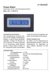
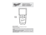
Service
Manual
pH communication functions
SM12B06J03-04E-E
1st Edition
2
Contents
Introduction3
1 Communication functions
1.1General
3
3
2Connection
2.1Connector pin allocation
3
3
3 Setting of communication condition
3.1Communication parameters 3
3
4 MODBUS communication protocol
4.1General
4.2Composition of message
4.3Address mapping
4.3.1 Memory contents
4.3.2 Read-out data 4.3.4. Description
4
4
4
4
4
4
4
5 Adress map and data format
5.1Data format 5.2Address map 5.3Supplement to address map
5.3.1 Impedance (IR11-13)
5.3.3 Model code (HR38-45)
5.3.4 Serial number (HR48-50)
5.3.5 Yokogawa Time Stamp (HR51-52)
5.3.6 FIR filter setting (HR56)
5.3.7 RUN register (HR58)
5.3.8 Sensor type for display (HR60)
5.3.9 TAG information reservation (HR1051-1100)
5
5
5
8
8
8
8
9
9
9
9
9
SM 12B06J03-04E-E
3
Introduction
This manual describes the communication function of
SENCOM pH sensors, in particular with regard to the sensors specific data and how to access this data.
The sensor is protected in order to prevent erroneous writing of data resulting in a dysfunctional sensor. Please read this manual and
reference documents carefully before using a Human Machine Interface to access data in the sensor.
Reference documents
IM 12B6J3-04E-EInstruction
IM 12B6J8-01E-EInstruction
IM 12B6J1-41E-EInstruction
IM 12B6W2-03E-EInstruction
Manual
Manual
Manual
Manual
FU20F pH/ORP SENCOM sensor
FU24F pH/ORP SENCOM sensor
SC25F pH SENCOM sensor
WU11 Interconnection extension cable for SENCOM sensor
Notices
• This manual is meant for software developers and engineers who want to access the SENCOM sensors memory outside the normal
scope of operation.
• Yokogawa Process Analyzers Europe B.V. (hereinafter referred to as YPA Europe) does not warrant that the functions will suit a
particular purpose of the user.
• No part of this document may be reproduced in any form without YPA Europe’s written permission.
• The contents of this manual are subject to change without prior notice.
• If any question arises or errors are found, or if any information is missing in this manual, please inform the nearest Yokogawa sales office.
1 Communication functions
3 Setting of communication condition
1.1 General
Bi-directional digital communication (RS 485) with limited
MODBUS support. SENCOM sensor is regarded as slave, the
Human Machine Interface (HMI) is regarded as master. Data
storage/transfer is done via Input registers (read only) and Hold
registers (read/write). Each register is 2 bytes.
The communication parameters of the HMI have to be set
correctly to work with the SENCOM sensors. In a multiple sensor
loop, each connected sensor must have a unique MODBUS
address (Slave ID).
2 Connection
Table 2:
Connection should be performed using the WU11
interconnection cable for SENCOM sensors.
2.1 Connector pin allocation
The definition of connector pin to WU11 cable and signal
description is given in Table 1.
Table 1:
Pin #
1
2
3
4
5
Signal description Wire color
Data -
Yellow
Data +
Green
Supply +
Brown
Shield
Black
Supply Gnd
White
3
5
Wire number
83
84
87
82
86
1
2
2
1
4
Figure 1: (front view)
Sensor connector, male
3.1 Communication parameters
The parameters to be set are shown in Table 2.
Item
Transmission speed *1
Data length
Stop bit
Parity setting
Slave ID *2
Factory default Setting range
9600bps
fixed
8 bits
fixed
1 bit
fixed
Even
fixed
1
1-247
Note:
*1 Transmission speed:
The transmission speed (baud rate) is configurable but part
of protected settings to guarantee proper working with the
FLXA21 analyzer. The default baud rate is set at 9600bps.
*2 Slave ID:
All sensors are set to Slave ID 1 by factory setting. This
Slave address can only be changed by using the SENCOM
MODBUS Slave Configuration Tool R2.02.
5
3
4
Figure 2: (front view)
Cable connector, female
SM 12B06J03-04E-E
4
4 MODBUS communication protocol
4.1 General
In MODBUS protocol the communication is always started by the
master station (e.g. HMI), where a slave station (e.g. SENCOM
sensor) responds to the received message.
4.3 Address mapping
Transmission procedures are:
1)The master station sends a command message to a slave
station with specified address.
2)The slave station checks whether the address in the received
message matches with the own Slave ID or not.
3)If matched, the slave station executes the command and
sends back the response message.
4)If mismatched, the slave sensor ignores the request and waits
for the next command message.
4.3.2 Read-out data
The read-out data is the specific data belonging to a parameter
(see Section 5.2)
For some parameter, the data contains a factor*, value and unit.
The master station can individually communicate with any one of
the slave stations connected on the same line upon setting the
Slave ID. in the command message.
4.2 Composition of message
Command message and response message consists of 4 fields
which are send in the following order:
1 Slave ID (1 byte)
2 Function code (1 byte)
3 Data (2 to 100 bytes) (limited to 50 addresses)
4 Error check code (CRC-16) (2 bytes)
Slave ID (1 byte)
Slave ID is the number specifying a slave station. The slave
station that corresponds to “Slave ID” number will execute a
command.
Function code (1 byte)
Function code tells the slave which table to access and whether
to read from or write to the table.
The following function codes can be used for SENCOM sensors:
Table 3:
Function
04 (04 hex)
03 (03 hex)
06 (06 hex)
16 (10 hex)
Action
Read
Read
Write single
Write multiple
Table Name
Analoge Input Registers
Analoge Output Holding Registers
Analoge Output Holding Register
Analoge Output Holding Registers
Data
Data contains a start address (register number), quantity of
addresses and the specific content of the addresses.
The register number transmitted on message is expressed as its
relative address.
The relative address is calculated by the following expression.
For example, when the register number designated by a function
code is 40003, relative address 0002 (=(lower 4 digits of 40003)
- 1) is used on the message.
First address is ‘0’ ~ 40001
Error check code
This is the code to detect message errors (change in bit) in the
signal transmission.
With the MODBUS protocol (RTU mode), CRC-16 (Cyclic
Redundancy Check) is applicable.
SM 12B06J03-04E-E
4.3.1 Memory contents
The memory contents describe the parameter.
Note:
* To maximize the information in the address, some information
in the address is written with a factor x. The x followed by a
number is the multiplying factor of the address content
(e.g. x10; the content in this address needs to be divided by
ten for corrected value).
4.3.3 Display
The display data is defined using one of the following methods
with the remark that for the Hexadecimal method and Binary
method the most significant bit (msb or MSB, also called the
high-order bit) is the bit position in a binary number having the
greatest value.
In a 2 address string the first (left) byte is defined as most
significant resulting in the second byte as least significant.
Singed/unsigned
16 bit signed numbers range from -32766 to +32767.
16 bit unsigned numbers range from 0 to +65535.
Hexadecimal
Long strings of ones and zeroes are difficult to read, so the bits
are combined and shown in hexadecimal code. Each block of 4
bits is represented by one of the sixteen characters from 0 to F.
0000
0001
0010
0011
=
=
=
=
0
1
2
3
0100
0101
0110
0111
=
=
=
=
4
5
6
7
1000
1001
1010
1011
=
=
=
=
8
9
A
B
1100
1101
1110
1111
=
=
=
=
C
D
E
F
Each block of 8 bits (called a byte) is represented by one of the
256 character pairs from 00 to FF.
Binary
A binary code represents text using the binary number system’s
two binary digits, 0 and 1. A binary code assigns a bit string to
each symbol or instruction. For example, a binary string of eight
binary digits (bits) can represent any of 256 possible values and
can therefore correspond to a variety of different symbols, letters
or instructions.
Long
To accommodate values that can reach beyond the 16-bit
limitation.
A 32-bit register represented in 32-bit Integer format is passed
via communications as two 16-bit registers:
High-Order Register =value/65536
Low-Order Register = value modulus 65536
(value = register high x 65536 + register low)
4.3.4. Description
Description contains the explanation how the read-out data
should be interpreted. In case the explanation covers calculations
or more details, the description in written in a supplement of the
address map (see Section 5.3).
5
5 Adress map and data format
5.1 Data format
The MODBUS protocol used RTU (Remote Terminal Unit) mode which means that transmitted data is “numeric value” and not ASCII
code”.
5.2 Address map
Table 4a: Input registers 3xxxx
Relative Register Memory contents
addressnumber
0000
30001
pH1-ref voltage
Read-out data
Display Description
×20: -15000…+15000mV
SignedmV value pH1-Ref;
(limits -20000...+20000mV)
0001
30002
pH2-Ref voltage
×10: -15000…+15000mV
SignedmV value pH2-Ref;
(limits -20000...+20000mV)
0002
30003
Ref-LE voltage
×10: -15000…+15000mV
SignedmV value Ref-LE;
(limits -20000...+20000mV)
0003
30004
pH1-LE
×10: -15000…+15000mV
SignedmV value pH1-LE;
(limits -25000...+25000mV)
0004
30005
pH2-LE
×10: -15000…+15000mV
SignedmV value pH2-LE;
(limits -25000...+25000mV)
0005 30006Reserved
Signed
0006
30007
pH value
×1000: -2000…+16000pH SignedpH value;
(limits -32000…+32000pH)
0007
30008
Temperature used
×100: -3500…+15500°C
Signed Temperature in °C;
in calculations
(limits -4000…+16000ºC)
0008
30009
ORP value
×10: -15000…+15000mV
Signed (limits -20000…+20000mV)
0009
30010
rH value
×100: 0...10000
Signed (limits -1000…+11000)
0010
30011
Glass Impedance pH 1
x 1: 10...10000kOhm
Signedvalue x or code -1, -2, -3, -4, -5, see 5.3.1
0011
30012
Glass Impedance pH 2
x 1: 10...10000kOhm
Signedvalue x or code -1, -2, -3, -4, -5, see 5.3.1
0012
30013
Reference Impedance
x 2: 5...2000kOhm
Signedvalue x or code -1, -2, -3, -4, -5, see 5.3.1
0013
30014
Board status :AD error
BinaryReflection of different status of sensor, error
configuration etc.
0014
30015
Temperature measured
×100 : -3500…+15500°C
Signed Temperature in °C;
value Pt1000
(Limits -5000…+17490°C)
0015
30016
Checksum value
-32768…+32768
Signed Calculated checksum value in case of
calculated by Sensor
checksum error of specific region
Table 4b: Input registers 3xxxx
Relative Register Memory contents
Read-out data
Display Description
addressnumber
0100
30101
Total time of operation
0...3600 seconds
UnsignedCounter in seconds of operating mode 1.
since last connection netto Counter resets every 3600 sec’s for the
purpose of hour counter (HR1019)
0101
30102
Temperature Electronics
x1: -150…+150°C
Signed Temperature value PCB; Only updated
uncompensated in °C during impedance measurement
0102
30103
Temperature electronics
x1: -150…+150°C
Signed Temperature value PCB; IR 30102
compensated in °C compensated for TOFS (HR 40057)
0103
30104
Total time of operation
0…65536 seconds
UnsignedCounter in seconds regardless of operating
since last connection mode. Counter reset after 65536 sec’s
0104
30105
Major software version
-32768…+32768
Unsignedsee 5.3.2
0105
30106
Minor software version
-32768…+32768
Unsignedsee 5.3.2
SM 12B06J03-04E-E
6
Table 5a: Hold registers 4xxxx
Relative Register Memory contents
Read-out data
Display Description
addressnumber
0000
40001
Communication speed
1:4800, 2:19200, other:9600 UnsignedDefault 9600bps
0001
40002
Module ID
PH: 0x04, SC: 0x08, Unsigned
ISC: 0x0C, DO: 0x10
0002
40003
Indentification number PCB
UnsignedUnique ID number PCB electronics
0003
40004
LE control level
0: disabled , UnsignedEnable LE control
other value = enabled
0004
40005
Prod. ordernumber High
1-999
UnsignedProduction order number PCB
0005
40006
Prod. ordernumber Low
1-999
UnsignedProduction order number PCB
0006
40007
Prod. ordernumber 1-999
UnsignedSerial number of panel in the production
serial number
batch
0007
40008
Production panel position 1-20
UnsignedPosition number of the sensor in a panel
000840009
:
:
Reserved
002740028
0028
40029
Design impedance
value @25°C (imp)
0-50000 MOhm
Unsigned
0029
40030
Delay factos (vf)
1-1000 (0=1)
Unsigned
0030
40031
Impedance config input 1 0: low 1: high
Unsigned
0031
40032
Impedance config input 2 0: low 1: high
Unsigned
0032
40033
Impedance config input 3 0: low 1: high
Unsigned
0033
40034
Impedance settling time
Seconds
UnsignedStable time parameter for impedance
measurement
0034
40035
Set impedance interval
Seconds
Unsigned
0035
40036
Sensor connection types 1, 2, 3, 4, 5, 6, 7, 8, 9
UnsignedHardware configuration setting of analogue
sensor to PCB.
0036
40037
Modbuss address number 1...247
UnsignedAll other address 1
0037 40038
:
:
Model code
See 5.3.3
Hex
16 bytes (alpha numeric) 8 address string
0046 40047
0045
40046
Unit rev.
x100 (two decimals)
UnsignedTest software ATE factory
0046
40047
Assy rev.
x100 (two decimals)
UnsignedHardware revision PCB
004740048
:
:
Serial No.
See 5.3.4
Hex
6 bytes, 3 address string 2 bytes
0049
40050
for production location
005040051
:
:
Date YOKOGAWA
See 5.3.5
UnsignedProduction date in seconds from:
0051
40052
TIME STAMP
2000-01-01-00:00:00
0052
40053
Available sensor type bit
Bit 0:PH, bit 1:ORP, bit 2 Binary The bit of this parameter is set by specific
PH+ORP, other bit are 0.
sensor type. This parameter is used by
FLXA and PC.
0: possible , 1:impossible
“PH8”: PH only, bit 1 and 2 are set to 1
“OR8”: ORP only, bit 0 and 2 are set to 1
“FU20”, “FU24”, “SC25”: all bits set to 0
0053
40054
Reserved
Reserved, prepared for FD YHQ
0054
40055
Temp. element
148
Signed Type code of temperature element for
display setting FLXA/PC
0055
40056
FIR settings for input reg 8 See 5.3.6
Signed Filter setting for Temperature value
(temp for measurements) of IR 30008
0056
40057
TOFS PCB temperature
x1: -150…+150°C
Signed Offset used for temp PCB measurement
in degree Celsius
0057
40058
Run
Measurement & data update
0 : stop, 1 : run 2: run
UnsignedMeasurement & data update. See: 5.3.7
0058
40059
JCSS(Japan Calibration
0 : Normal
Service System) mode 1 : Japanese
Unsigned
158 : PH
Sensor type; setting for calculation used for
0059
40060
Sensor type (of display)
159 : ORP
UnsignedpH, ORP and RH. Also function for display
160 : PH+ORP
Setting FLXA/PC See: 5.3.8
0060
40061
TOFS
×100: -10...+10°C
Signed (Limits: -1000...+1000ºC)
0061
40062
Temperature measuring
0: manual, 1: automatic
Unsigned
manual or automatic (using sensor value)
0062
40063
Set manual temp value
×100 : -3500..+15500°C
Signed
0063
40064
ITP
× 1000: 0..14000 pH
Signed
0064
40065
PHZERO1
x 10 : -5000…+5000mV
Signed
SM 12B06J03-04E-E
7
Table 5a: Hold registers 4xxxx (contineud)
0065
40066
PHSLOPE1
x 100 : 7000…11000%
Signed
0066
40067
pH 3 points CAL flag
0 : none, 1: ITP, 2 : 3point
Unsigned
0067
40068
pH 3 points CAL direction
Signed
0068
40069
pH 3 points CAL cross
×100 mV
Signed
points mV
0069 40070Reserved
0070
40071
pH 3 points CAL PHZERO2x 10: -5000…+5000mV
Signed
0071 40072Reserved
0072
40073
pH 3 points CAL SLOPE2 x 100: 7000...11000%
Signed
0073 40074Reserved
0074 40075Reserved
0075
40076
ORP slope
x 100: 7000…11000%
Signed
0076 40077Reserved
0077
40078
ORP zero most significant x 100: -50000…+50000mV Long
0078
40079
ORP zero least significant
0079
40080
Auto correct mode
0:Disable, 1:Enable
Signed
0080
40081
Auto correct zero
x 10: -5000…+5000mV
Signed
0081
40082
Auto correct slope
x 100: 7000…11000%
Signed
0082
40083
pH calibration date
1st byte = Year,
2nd byte = Month
Hex
0083
40084
1st byte = Day,
2nd byte = Hours
Hex
0084
40085
1st byte = Minutes,
2nd byte = Seconds
Hex
0085
40086
ORP calibration date
1st byte = Year,
2nd byte = Month
Hex
0086
40087
1st byte = Day,
2nd byte = Hours
Hex
0087
40088
1st byte = Minutes,
2nd byte = Seconds
Hex
008840089
:
:
Reserved for calibration
0089
40090 data
0090
40091
Not used. These area are not included in
:
:
Reserved
CRC target or back-up mechanism.
0099
40100
If these area are used, these parameter will
not be saved to back up area.
Table 5b: Hold registers 4xxxx
Relative Register Memory contents
Read-out data
Display Description
addressnumber
1000
41001
Set temperature high
×100 : -3500…+15500mV Signed Used for internal loggings
1001
41002
Set pH low
×1000 : -2000…+16000mV Signed Used for internal loggings
1002
41003
Set pH high
×1000 : -2000…+16000mV Signed Used for internal loggings
1003
41004
Set logging interval
hours
UnsignedUsed for internal loggings
1004
41005
Yokogawa time stamp
Seconds from
2000-01-01-00:00:00
UnsignedActual time updated by FLEXA
1005
41006
Yokogawa time stamp
Unsigned
1006
41007
Yokogawa time stamp
Use first logging time (after
3600 seconds up to 24 hr) UnsignedTime of first customer use.
1007
41008
Yokogawa time stamp
Seconds from
2000-01-01-00:00:00Unsigned
1008 41009Reserved
1009 41010Reserved
1010
41011
Maximum temperature ×100: -2000…+15000°C
Signed Value is updated if maximum is valid for
exposed
more than 1 minute
1011
41012
Minimum temperature
×100: -2000…+15000°C
Signed Value is updated if minimum is valid for
exposed
more than 1 minut
1012
41013
HRS pH low
0…65536
Signed Total hrs of pH below set point
1013
41014
# pH low
0…65536
UnsignedNumber of time that pH value is lower than
set point for at least 1 minute
Value need to be reached for more >1 min.
1014
41015
HRS pH high
0…65536
Signed Total hrs of pH above set point
1015
41016
# pH high
0…65536
UnsignedNumber of time that pH value is higher than
set point for at least 1 minute
Value need to be reached for more >1 min.
1016
41017
Lowest pH reached
×1000 : -2000…+16000mV Signed Value need to be reached for more >5 min.
SM 12B06J03-04E-E
8
Table 5b: Hold registers 4xxxx (contineud)
Relative Register Memory contents
Read-out data
Display Description
addressnumber
1017
41018
Highest pH reached
×1000 : -2000…+16000mV Signed Value is updated is maximum is valid for
more than 5 minutes
1018
41019
Total time of operations
0…65536
UnsignedDays
1019
41020
Total time of operations
0…65536
UnsignedHours
1020
41021
HRS temp high
0…65536
UnsignedTotal hrs of temp above set point
1021
41022
# Temp high
0…65536
Signed Number of time that temp is higher than set
point for at least 1 minute
Value need to be reached for more >1 min.
Table 5c: Hold registers 4xxxx
Relative Register Memory contents
addressnumber
1050
41051
Reserved for tool
:
:
1099
41100
TAG information
Read-out data
Display Description
t.b.d.
t.b.d.
See 5.3.9
5.3 Supplement to address map
5.3.1 Impedance (IR30011-30013)
The impedance value measured by the sensor is measured
automatically or on request (see Section 5.3.7) and the result in
written in IR30011 to IR30013.
Dependent on the sensor type, the impedance value is valid or
not valid. A non-valid impedance value is identified with an error
code, see Table 6 and Table 7.
5.3.2 Software revision (IR30105-30106)
Input registers IR105-106 contains the software revision.
The software revision is divided in a major revision number
which is stored in IR105 and a minor revision number
which is stored in IR106.
Combined the addresses show the complete revision number
as XX.XX
The glass impedance is measured on pH1 and/or pH2 input. The
reference is measured on pHref input. The electronics of these
inputs are optimized for the high ohmic pH glass electrode or the
low ohmic reference electrode.
The inputs are pre-defined in Hold registers 40031, 40032 and
40033. If a pH glass electrode is used as measurement element,
the impedance is High and the setting of the Hold register is 1.
In case of a reference electrode, the impedance is Low and the
setting of the Hold register is 0.
The Hold register settings 40031-40033 are corresponding with
30011-30013.
5.3.3 Model code (HR40038-40047)
Hold registers HR38 – 47 contain the modelcode. The format
of the modelcode is a string of maximum 16 ASCII codes, each
ASCII code is 1 byte. Each Hold register address has two (2)
bytes which means that two (2) ASCII codes can be stored.
The hexadecimal representations of both ASCII codes are added
and converted to a decimal number that is stored in the Hold
register address.
Table 6: Glass impedance 10…10000 kOhm = value for Glass impedance
< 100 kOhm
= Glass breakage
> 100 kOhm
= a correct glass impedance
0= no measurement value available
-1= almost 0, maybe shorted or glass breakage
-2= < 10 kOhm, glass breakage
-3= above lineair range. > 10 MOhm
-4= above lineair range. > 200 MOhm
-5= No good calculation. Airbubble/dry measurement etc.
Table 7: Reference impedance
5…2000 kOhm
= value for Reference impedance
0= no measurement value available.
-1= almost 0, maybe shorted, function of reference good
-2= low, below linear range, function of reference good
-3= above linear range. Out of spec.
-4= too high, probably open/dry. Out of spec.
-5= No good calculation. Airbubble/ dry measurement etc.
SM 12B06J03-04E-E
Example:
Modelcode FU20F-NPT:
F= 70 (ASCII code) U= 85 (ASCII code) = 46
= 55
(hex)
(hex)
Added: Converted:
= 4655 (hex)
= 18005 (dec)
The result is stored in Hold register HR40038
2 = 50 (ASCII code)
= 32 (hex)
0 = 48 (ASCII code)
= 30 (hex)
Added:
Converted:
= 3230 (hex)
= 12848 (dec)
The result is stored in Hold register HR40039
Etc.
5.3.4 Serial number (HR40048-40050)
Hold registers HR48 - 50 contain the Serialnumber. The
format of the Serial number is a string of four (4) ASCII codes
representing characters (N3YM) and five (5) ASCII codes
representing a decimal number (xxxxx). The translation method
of the ASCII codes representing the characters is the same as
for the Modelcode (see Section 5.3.3). The results are stored in
HR48 and HR49. The ASCII codes representing the numbers is
stored as unsigned integer in HR50.
9
5.3.5 Yokogawa Time Stamp (HR40051-40052)
The Yokogawa Time Stamp is the number of seconds elapsed
since 01/01/2000 00:00:00. This unsigned integer is stored in 2
Hold register addresses (4 bytes).
The seconds are converted to hexadecimal format. The first 4
‘digits’ are stored in HR40051 as (hexa)decimal, the second 4
‘digits’ are stored in HR40052 as (hexa)decimal.
Example:
Date: 25/11/2014 10:23:52 => Yokogawa Time Stamp =
470226232 seconds
Converted: => 1C071538 (hex)
The result 1C07 (hex) or 7175 (dec) is stored in Hold register
HR40051, the result 1538 (hex) or 5432 (dec) is stored in Hold
register HR40052.
5.3.6 FIR filter setting (HR40056)
The FIR register is a filter on the last three measurements. Each
measurement can be set with an individual weight factor, but the
total factor has to be lower than 256. In general the weight factor
of the last measurement and the second last measurement are
set, and the weight factor of the first measurement is calculated
(all three weight factors added will give 255).
In the FIR register we can describe the last and the second last
weight factor of measurement using one address.
This address is 16 bits where the least significant 8 bits are
describing the weight factor of the last measurement and most
significant 8 bits are describing the weight factor of the second
last measurement.
Example:
first
2nd last
last
Moving average:
111
Total number
Weight factor: 858585 255
||||
Hexadecimal notation:
55
55
5555
Decimal notation:
85
85
21845
5.3.7 RUN register (HR40058)
The sensor has different operating modes, all regulated by the
Run register.
Run register value:
0 = no measurements
1 = pH-, temperature-, ORP-, impedance measurements on set
interval time (defined in HR40035)
2 = same as run1 but starts routine with impedance
measurement.
By factory default the sensor is set to run mode 1 (hold register
40058). This means that when the sensor is powered, the
pH measurement will start immediately and the impedance
measurement will be performed after 120 seconds as set in the
interval register (default value).
So for the first two minutes the input registers corresponding
the impedance values are 0 (see Section 5.3.1) If an impedance
measurement is preferred directly from start on, the sensors run
register (40058) should be set to value 2.
Be aware that a change of the run register to 1 or 2 should
always be proceded by a run=0 setting with an interval of
500ms in between each setting or a power off/on sensor.
5.3.8 Sensor type for display (HR40060)
The setting of the sensor type for display defines the calculation
methot for ORP.
Setting 158: Only pH is calculated and values for ORP and rH
are fixed to 0 in the input registers.
Setting 159: The ORP is calculated using pH as reference glass
which gives a pH compensated ORP value stored in input
register 30009.
Setting 160: pH, normal ORP and rH are calculated.
5.3.9 TAG information reservation (HR41051-41100)
These addresses are reserved for third parties to enter TAG
information. The content of these registers are not part of any
CRC check or back-up mechanism.
SM 12B06J03-04E-E
10
SM 12B06J03-04E-E
11
SM 12B06J03-04E-E
YOKOGAWA HEADQUARTERS
9-32, Nakacho 2-chome, Musashinoshi
Tokyo 180
Japan
Tel. (81)-422-52-5535
Fax (81)-422-55-1202
www.yokogawa.com
YOKOGAWA CORPORATION OF AMERICA
2 Dart Road
Newnan GA 30265
United States
Tel. (1)-770-253-7000
Fax (1)-770-251-2088
www.yokogawa.com/us
YOKOGAWA EUROPE B.V.
Euroweg 2
3825 HD AMERSFOORT
The Netherlands
Tel. +31-88-4641 000
Fax +31-88-4641 111
www.yokogawa.com/eu
YOKOGAWA ELECTRIC ASIA Pte. Ltd.
5 Bedok South Road
Singapore 469270
Singapore
Tel. (65)-241-9933
Fax (65)-241-2606
www.yokogawa.com/sg
SM12B06J03-04E-E
Subject to change without notice-
Copyright©
Yokogawa has an extensive sales and
distribution network.
Please refer to the European website
(www.yokogawa.com/eu) to contact your
nearest representative.
Printed in The Netherlands, 01-1503 (G) I