1
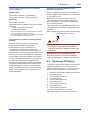
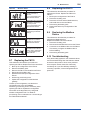
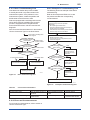
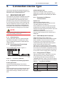
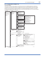
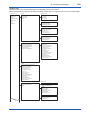
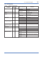
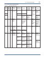
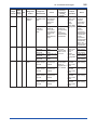
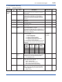
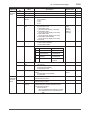
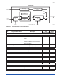
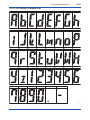
7-4 <7. Setting Parameters> (2) Menu Tree 7.3.4 Tag and Device Information Menu Tree is depending on the connection device type. Refer to section 9 “Connection Device Type” for the menu tree of our recommended device configuration tool. Refer to subsection 8.2 “Recommended products list” for the device configuration tool of our recommendation. You can specify the Device Tag when ordering the corresponding FN110 Field Wireless Communication Module. Device Tag and device information can be checked as follows. 7.3.3 Parameters for Wireless Communication (1) Network Information CO block: Configuration The network-related information can be checked. (2) Update Time CO block: Data publication period Set the update time value to 8 to 3600 seconds. The setting affects the battery life. When update time is set 0 second, FN310 stops updating process variables via the field wireless network. And it also stops the acquisition of process variables from the Modbus device. (3) Remaining Battery Life UAPMO block: Energy Left The number of days of battery life remaining is indicated assuming ambient temperature condition as 23 °C. It takes several days for the value to be stabilized after the power on and initialization of the remaining battery life. UAPMO block: Reset Energy Left When changing batteries, the remaining battery life is initialized by Reset Energy Left parameter. (4) LCD Display TRANSDUCER block: LCD Intermittent Time The integral indicator has three modes: Continuous, Intermittent, and Off. These modes are switched by LCD Intermittent Time parameter. The intermittent mode repeats on/off at defined seconds. In any mode, current process value is displayed by magnet switch operation. After displaying current process value, returns to the configured mode. Refer to subsection 8.6 “Switching LCD Display” for details. Procedure to Read the Device Tag and Device Information • Device Tag (Software Tag) This is specified by writing characters (up to 16 characters) that differs from those specified in Tag No. to the module. For details how to confirm this, refer to subsection “Connecting to the Field Wireless Network”. • Tag Description This is a universal parameter to store the comment that describes the content of the tag located in the TRANSDUCER and AI1/AI2/AI3/ AI4 blocks. Limitation of Device Information When changing the device information, input the information based on the following limitation on the number of characters. • Message function (up to 32 characters) TRANSDUCER block: Tag Description AI1/AI2/AI3/AI4 block: Tag Description 7.3.5 Setup the Integral Indicator TRANSDUCER block: LCD Exp Mode Set the display method of the PV on the integral indicator. Index display or base display is selectable 7.3.6 Parameters for Modbus Device Parameters for Modbus device is depending on the connection device type. Refer to section 9 “Connection Device Type”. 7.3.7 Assignment to AI Object FN310 has four AI blocks. Input value of Process Value parameters for each AI block depends on the setting of the Sensor Type parameter of TRANSDUCER block. Refer to section 9 “Connection Device Type”. NOTE When the FN310 detects AL.01, AL.02 and AL.03 error, the LCD display does not dim regardless of the status in LCD mode. See Table 8.4 for details. IM 01W03D02-01EN