1
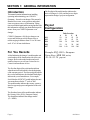
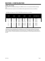
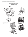
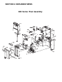
COINCO QUANTUM •
FOUR TUBE
O P E R AT I O N A N D S E R V I C E MANU A L
TABLE OF CONTENTS
Section 1: General Information
Introduction ...................................................................................... 4
For Your Records ............................................................................. 4
Payout Configurations ....................................................................... 4
Features ........................................................................................... 5
After Unpacking ............................................................................... 5
Specifications ................................................................................... 6
Section 2: Installation
Installing the Changer ........................................................................ 6
Section 3: Configuration
MDB Changers ................................................................................ 9
Filling the Coin Tubes ........................................................................ 9
Float Mode .................................................................................... 10
Setting the Float Mode Levels ......................................................... 10
Activating Float Pay-Down ............................................................. 10
Changing the Coin Tubes ................................................................ 10
Rerouting the Coins ........................................................................ 12
Section 4: Maintenance
Routine Maintenance ...................................................................... 13
Cleaning ......................................................................................... 13
Removing/Replacing Individual Modules .......................................... 14
Clearing Coin Jams ......................................................................... 14
Section 5: Troubleshooting
Troubleshooting Guide .................................................................... 15
Section 6: Exploded Views
Exploded Views ............................................................................. 17
900 Series
Page 3
SECTION 1: GENERAL INFORMATION
Introduction
This manual contains information on installing,
operating and maintaining your COINCO
Quantum € four tube coin changer. This manual is
intended for owners, route operators and technicians as a primary source of information. Taking
time to read this manual and becoming familiar with
this information will help you obtain the best performance from your COINCO Quantum€ coin
changer.
COINCO Quantum € 900 Series changers can
accept and validate up to16 different coins or
tokens ranging in diameter from 15.0 to 28.0 mm
and 1.07 to 2.40 mm in thickness.
For You Records
A label indicating the changer’s model number and
serial number can be found on the side of the coin
changer. Refer to the model number and serial
number whenever you call your Coinco Service
Center for information or service.
The first digit of the model number indicates the
series of changer (9= 900), and the last two digits
represent the changer’s payout configuration.
Payout
Configuration
901
902
904
906
907
A
.50
.02
2.00
.50
2.00
Tube Location
B
C
.10
.05
.01
.05
.50
1.00
.10
.20
1.00
1.00
D
.20
.20
2.00
1.00
2.00
Example:EUQ-G901= European
Union Euro, MDB 900 series,
.50-.10-.05-.20 payout
The first four digits of the serial number indicate
when the unit was built which is also the beginning
of the warranty period. The first two digits indicate
the week of manufacture; the third and fourth digits
indicate the year of manufacture. For example,
Serial Number 030307053 would indicate the unit
was manufactured in the 3rd week of 2003.
The model number indicates the country, currency,
interface type and payout configuration of the coin
changer.
The first three letters of the model number indicate
the Country Code (EUQ= European Union).
The fourth letter indicates the changer model
(G = MDB).
Page 4
900 Series
SECTION 1: GENERAL INFORMATION
Features
After Unpacking
€ The COINCO Quantum € coin changer has a
modular design for easy service.
€ Individual tubes snap in and out for
easy customization.
€ Coin tubes are clearly marked with coin denomination in bold white numbers.
€ Programmable acceptor allows for easy
reconfiguration of coin tubes in the field.
€ Hinged front cover simplifies tube removal and
serviceability.
€ Acceptor “Park Position” allows easy access to
the coin tubes.
€ Pays change from self-loading high capacity
change tubes.
€ Two motors provide fast accurate payout.
€ All models equipped with the MDB
protocol.
€ Lightweight, rugged plastic construction.
€ State-of-the-art electronic logic system is
designed for reliability and performance.
After unpacking the unit, inspect it for any possible
shipping damage. If the unit is damaged, notify the
shipping company immediately. Only the consignee
(the person or company receiving the unit) can file a
claim against the carrier for shipping damage. We
recommend that you keep the original carton and
packing materials to reuse if you need to transport
or ship your changer in the future.
900 Series
If the coin changer is being stored or used as a
spare, always keep it in its shipping carton when not
in use. This will keep it clean and offer the best
protection for the unit.
Page 5
SECTION 2: INSTALLATION
Specifications
Power Requirements (by model)
EUQ-G9XX ........................................... 34V DC
EUQ-G92X ............................................ 12V DC
Operating Temperature
0 to 150 Degrees Fahrenheit
-18 to 65 Degrees Celsius
Storage Temperature
-22 to 160 Degrees Fahrenheit
-30 to 72 Degrees Celsius
Relative Humidity
20% to 98% Noncondensing
Operating Attitude
Vertical +3 degrees
Physical Dimensions
Height: 14.77 inches (base to top of coin
return lever)
Width: 5.47 inches
Depth: 3.25 inches (gateopen)
3.00 inches (gate closed)
Shipping Weight
Approximately 3.1 Kilos
Coin Tube Capacity
.01
.02
.05
.10
.20
.50
1.00
2.00
Page 6
Low Sensor Full Sensor Hand Load
Level
Level
Level
6
76
86
6
74
86
6
73
86
4
64
75
4
57
68
3
50
61
3
52
62
4
56
69
Installing The Changer
1.
2.
Remove power from vendor.
Remove the acceptor from the changer by
pressing down on the acceptor latch, releasing
the acceptor. Rotate the top of the acceptor
forward, away from the changer (see figures 1
and 2). Unplug the ribbon cable from
changer. Free the lower acceptor studs from
the changer housing. Place the acceptor in a
clean area.
3. With the acceptor removed, set the mounting
holes in the back of the changer housing over
the mounting screws in the vendor. Tighten
snugly (see figure 3).
4. Re-install the acceptor by inserting the lower
acceptor studs into the changer housing
guides. Plug the ribbon cable into the changer
(see figure 2).
5. Plug changer harness into vendor socket.
6. Press top of the acceptor into the changer
housing until the acceptor latch locks.
7. Load the tubes with coins (see “Hand Loading” and “Loading Through the Acceptor”).
(see figure 4).
8. (Optional) Set the coin tube float levels
(refer to “Setting The Float Mode Levels”).
9. Check to make sure the front cover and
acceptor are properly installed.
10. Apply power to the vendor.
11. Set the desired vend price and options on the
machine (refer to “Machine Manual)
12. Test the changer with a variety of coins to
ensure proper operation.
900 Series
SECTION 2: INSTALLATION
Figure 1
Figure 2
900 Series
Figure 3
Figure 4
Page 7
SECTION 2: INSTALLATION
“G” Moddel Controller/Vendor Interface
EUQ-G
Page 8
900 Series
SECTION 3: CONFIGURATION
MDB
SETTING THE VEND PRICE
Vend prices for MDB coin changers are set
through the vending machine controller (VMC).
See vending machine manual for details.
MANUAL FILL MODE
Manual fill mode can be used to fill the tubes of the
coin changer, through the acceptor, without accumulating credit and having to vend the credit away.
Filling the Coin Tubes
To enter the Manual Fill Mode, press inventory
buttons C and D at the same time. The acceptor
LED will flash an equal pattern of ON and OFF to
indicate the Manual Fill Mode is active. Coins
inserted through the acceptor will be routed to their
proper tubes. When the upper tube sensor is
reached, coins will be directed to the cash box or to
the next tube of like coins.
HAND LOADING
To hand load the coin tubes, tilt the coin tube
loading door open, load the four tubes with appropriate coins. Make sure all coins lay flat and
that each tube is filled at least to the 20% mark
.01 = 15-16 coins .02 = 15-16 coins
.05 = 15-16 coins .10 = 23-24 coins
.20 = 18-19 coins 1.00 = 15-16 coins
2.00 = 18-19 coins
The changer will automatically exit Manual Fill
Mode after 45 seconds of no actitivty, or if an
inventory switch is pressed and released.
Payout at least two coins from each tube to verify
tubes are loaded correctly.
LOADING THROUGH THE ACCEPTOR
Hand laoding coins directly into the coin tubes and
making sure they lay flat is one way to fill the Four
Tube changer with coins. If you are keeping track
of the DEX information for accounting purposes,
the coins loaded into the tubes need to be counted
by the VMC.
• Use the vending machine controller board’s
“Tube Fill” or “Coin Fill” mode. Refer to the
vending machine manual for details.
900 Series
Page 9
SECTION 3: CONFIGURATION
Float Mode
Float Mode is used to reduce the number of coins
kept in a tube to a level anywhere between the
upper and lower tube sensors.
The Quantum changer supports one of two
factory programmed Float Mode operations. They
are Float Level and Float Pay-Down..
FLOAT LEVEL (standard on EUQ
models)
In Float Level, coins are filled to a chosen
level betweeen the upper and lower tube sensors.
Once the Float Level is set, coins will only be
routed to the tube if a coin was paid out for change.
Accepted coins normally routed to that tube will be
sent to the cash box.
FLOAT PAY-DOWN (Optional, can be
ools)
Tools)
set in the factory or via Quantum T
In Float Pay-Down, coins are filled to a
chosen level between the upper and lower tube
sensors. Once the level is set, coins will continue
being routed to the tube until the upper sensor is
covered, then they will be routed to the cash box.
Activating the Float Pay-Down by pressing inventory buttons A and B simultaneously will pay down
any coins above the level you previously set. After
the coins are paid down, the acceptor will automatically go into manual fill mode. In manual fill mode,
the acceptor will only route coins to tubes that are
below the set level. Once the level is reached, the
coins will be rejected.
SETTING THE FLOAT MODE LEVELS
The Float Mode Levels for both Float Level and
Float Pay-Down are set for all four tubes using the
acceptor inventory buttons.
1. Using “Tube Fill”, “Coin Fill”, or Manual Fill
mode, fill the four tubes to the float level you
want the changer to maintain.
2. Press and release the A and D inventory buttons
simultaneously. The acceptor LED will flash an
equal ON and OFF pattern.
Page 10
3. Within two seconds, press and release inventory
buttons B and C at the same time to store the
tube levels and turn the Tube Float Mode ON.
The acceptor LED will now display a flash
pattern of 10% ON and 90% OFF to indicate
the levels are set.
Note: To turn off the Float Mode, repeat steps 2
and 3.
ACTIVATING FLOAT PAY-DOWN
Press and release acceptor inventory buttons A and
B simultaneously. After the tubes pay down,
Manual Fill Mode is automatically entered to allow
low tubes to be replensihed through the acceptor.
When the float levels are reached, coins are directed to the coin return. The changer will automatically return to operating mode after 45 seconds
of no activity or if any inventory button is pressed
and released.
Changing the Coin Tubes
REMOVING/REPLACING THE TUBES
To change the coin tubes, remove the acceptor from
the changer housing. Next, open the front cover by
gently pulling outward on the left side, swinging it
open to the right.
Remove the four inventory tubes one at a time
(starting from the left side and working to the right)
by pulling upward.
Replace the tube and shim assemblies by inserting
the tube’s dovetails into the guides in the housing and
push down.
900 Series
SECTION 3: CONFIGURATION
TUBES AND SHIMS
The coin tubes for your Quantum changer are diffdifferent sizes to accommodate the different diameter
coins.
Each coin tube has a removable, color-coded shim which adjusts the tube for the coin’s thickness.
For EUQ coin changers, the COIN/TUBE/SHIM combinations areas follows:
COIN
TUBE#
PART#
SHIM
PART#
TUBE/SHIM ASSY#
.01.00
.02
.05
.10
.20
.50
1.00
2.00
#10
#9
#7
#8
#7
#5
#6
#4
408270-1
408270-2
408270-3
408270-4
408270-5
408270-6
408270-7
408270-8
(Blue)
(Blue)
(Blue)
(Lt. Gray)
(Lt. Gray)
(Lt. Gray)
(Dk. Gray)
(Lt. Gray)
921462
921462
921462
921802
921802
921802
922023
921802
408282-1
408282-2
408282-3
408282-4
408282-5
408282-6
408282-7
408282-8
The shims are removed and replaced by sliding them on or off of the bottom of the tube. Do not reuse
shims. Continuous installation and removal can stress the plastic, causing the shims to lose their ability to
stay firmly in place. The shim is installed correctly if tits part number is visible looking at it from the rear of
the tube.
900 Series
Page 11
SECTION 3: CONFIGURATION
Rerouting the Coins
Whenever the coin tubes are rearranged, the
programmable acceptor has to be reconfigured to
route accepted coins to either the correct tube or
vendor cashbox.
To reconfigure the acceptor, apply power to the
Quantum € changer.
· Press inventory buttons A B and D simultaneously for 2 seconds (until the acceptor LED
goes out).
· Release the inventory buttons, and the LED will
flash an alternating pattern of 1-second ON/
1second OFF, then 2 seconds ON/ 2 seconds
OFF. This indicates the rerouting process is
waiting for a coin destination (coin tube or
cashbox) to be selected.
· To select a coin tube, press and release its
inventory button. Once the coin destination has
been selected, the LED will flash a 1-second50% ON / 50% OFF sequence.
· Drop the appropriate coin for the tube you have
chosen into the acceptor. An accepted and
validated coin will be routed and assigned to the
tube you’ve chosen.
Page 12
Example: For a payout configuration of
.50 – .10 – .05 – .20 (EUQ-901)
-Press and release inventory button A,
insert a .50 coin through the acceptor.
-Press and release inventory button B,
insert a .10 coin through the acceptor.
-Press and release inventory button C,
insert a .05 coin through the acceptor.
-Press and release inventory button D,
insert a .20 coin through the acceptor.
Any coin dropped through the acceptor before a
coin tube is selected will be routed to the vendor’s
cashbox. Valid coins not assigned to a tube will
also be routed to the cashbox.
· To save the new routing information and exit the
routing mode, hold the coin return lever down
for 4-5 seconds (until the acceptor LED returns
to its normal pattern) or wait 45 seconds and the
changer will automatically save the routing
information and exit this mode.
NOTE: If power is removed from the changer
before the rerouting information is saved, all
new routing information will be lost.
900 Series
SECTION 4: MAINTENANCE
Routine Maintenance
Cleaning
Routine maintenance will improve performance and extend the life of your Quantum
changer and reduce the need for more involved
repairs. Frequency of maintenance will depend
on environment and number of transactions.
The majority of your Quantum changer is
manufactured from a high-quality plastic, which
should be cleaned with a warm water and mild
detergent solution.
The coin changer should be kept in its
original shipping carton when not in use. This
will keep the changer clean and offer the best
protection for the unit.
CAUTION:
•Never submerge changer in water.
•Do NOT use petroleum solvents,
steel wool, scouring pads, or metal
brushes for cleaning.
•Do not spray any part of the changer
with any type of lubricant.
Since all coins share a common coin ramp,
heavy usage or a dirty environment can result in
dirt build-up in the acceptor. To clean the coin
ramp, lift the acceptor gate upward and diagonally to the right. Hold the gate to prevent it
from snapping back. Wipe the exposed coin
ramp and inner surfaces with a damp cloth. Be
cautious not to harm the coin stabilizer (clear,
thin piece of film). If the coin stabilizer looks
buckled, wrinkled, or is peeling off, replace it at
this time.
Figure 6
For excessively dirty units, use a damp cloth
with a mild detergent. DO NOT SUBMERGE
UNIT IN WATER.
For more detailed cleaning of the acceptor,
remove the front cover by opening the coin tube
loading door and wedge your thumb underneath
the front cover. To remove the cover, push out
and up. Next, remove the intermediate cover
using a small screwdriver to release tab on the
right side of the acceptor. Pivot the intermediate
cover out towards the left. Lift the metal
debounce rail out of the acceptor. You are now
able to fully clean the interior coin rail, gates
and the intermediate cover (pay attention to the
mirrored surface on the intermediate cover).
Reassemble the acceptor in the reverse order.
NOTE: When installing the intermediate cover,
make sure the metal debounce rail is in place
and raise the anti-stringing door on the accept/
reject gate before snapping the cover in place.
900 Series
Page 13
SECTION 4: MAINTENANCE
Removing/Replacing
Individual Assemblies
ACCEPTOR
To remove the acceptor, press down on the
acceptor latch and pull the top of the acceptor
forward and away from the changer housing.
Unplug the ribbon cable from the changer.
Raise the acceptor and pull outward until the
acceptor clears the housing slots.
FRONT COVER AND TUBE SHIELD
Remove the front cover by swinging the door
open to the right. Lift the front cover off of the
hinges on the changer housing. Lift the tube
shield off the top of the coin tubes.
REMOVING THE TUBES
The tubes are held in place by 3 sets of tabs that
secure it to the payout base.
To remove the tubes, start with the tube on the
left side and pull it straight up. Working your
way to the right, remove all four individual
tubes.
REMOVING THE LOGIC BOARD COVER
To remove the logic board cover, first remove
the strain relief bracket and screw. Next, remove the screw in the lower center portion of
the logic board cover. Lift the cover out.
REMOVING THE UPPER TUBE
SENSOR BOARD
Connected to the bottom of the main logic board
is the upper tube sensor board. To remove the
sensor board, release the locking tab and gently
pull the sensor board out. As you pull the sensor
board out, hold the main logic board in place
and the sensor board will unplug from the main
logic board.
Page 14
REMOVING THE LOGIC BOARD
Unplug the remaining harnesses from the main logic
board and lift it out of the housing.
REMOVING THE PAYOUT BASE
ASSEMBLY
With the harnesses disconnected from the main
logic board, remove the two screws (one on each
side) from the changer housing. Lay the changer on
its back and spread the sides of the housing apart.
Pull up and out on the payout base assembly.
REMOVING THE CASHBOX CHUTE
From the backside of the changer housing, remove
the tape seal from the cashbox chute. Lift the
bottom of the chute up and slide the cashbox chute
out.
Clearing Coin Jams
Should a coin jam occur in the cash box chute area,
use the following steps to help dislodge the coins:
1. Remove changer from vendor.
2. From the backside of the changer housing,
remove the tape seal from the cashbox chute.
Lift the bottom of the chute up and slide the
cashbox chute out.
3. Remove any lodged coins.
4. Replace the cashbox chute by pressing in and up
to snap into place.
900 Series
SECTION 5: TROUBLESHOOTING
TROUBLESHOOTING GUIDE
TROUBLE
POSSIBLE CAUSE
PROCEDURE
REMEDY
No Coin Acceptance
No power
Make sure changer
is plugged into vendor.
Plug changer
into vendor.
Acceptor
Check Acceptor LED.
If LED is on, replace acceptor.
Replace acceptor.
If still no coin acceptance,
Replace changer’s
main logic board.
If still no coin acceptance,
Replace changer’s
main power harness.
If Acceptor LED is off, check
to see that acceptor cable and
changer power harness are
properly connected to changer’s
main logic board.
Plug acceptor cable and/or
changer power harness
into changer main logic
board.
If still no coin acceptance,
Replace changer’s
acceptor logic board.
If still no coin acceptance,
Replace changer’s
main power harness.
No Coin Acceptance
Rejects Percentage
of Good Coins
Accepts Coins But
Gives No/Or Erratic
Credit
900 Series
No vend price set
Set vend prices (see “Setting The
Vend Price” section of this manual)
Coin Return Lever
Make sure changer is mounted
correctly and coin return lever
is in proper position
Reposition changer and/or
vendor coin return.
Acceptor is dirty or foreign
matter in coin accept path
Check to see that acceptor coin
path is clean and free of matter
Clean acceptor and remove
any foreign matter.
If still rejects good coins,
Replace acceptor.
If still rejects good coins,
Replace changer’s main
logic board.
Replace acceptor with good
acceptor and test to see if
changer functions properly.
Replace defective acceptor.
If still no/erratic credit,
Replace changer’s main
logic board.
If still no/erratic credit,
Replace changer’s main
power harness.
Acceptor
Page 15
SECTION 5: TROUBLESHOOTING
TROUBLESHOOTING GUIDE
TROUBLE
POSSIBLE CAUSE
PROCEDURE
REMEDY
Accepted Coins Always
Go to Cashbox
Front Cover
Check front cover for proper
installation, check the mirrors
Clean or replace front cover.
Acceptor
If coin still goes to cashbox,
replace acceptor with good
acceptor and test to see if changer
functions properly.
Reprogram acceptor coin
routing.
If coin still goes to cashbox,
Replace acceptor.
Check the sensor board for loose
components. Make sure tube
sensor board is properly secured
to main logic board. Check cable
from sensor board for damage or
improper connection.
Replace tube sensor board.
If coin still goes to cashbox,
Replace changer’s main
logic board.
Coin tube gate is in
the open position
Remove acceptor back cover
and check solenoid for free
operation.
Replace acceptor.
Tube Sensor Board
Replace tube sensor board with
good board and test to see if
changer functions properly.
Replace tube sensor board.
If coins still go to tubes,
Replace changer’s main
logic board.
Vendor
Make sure VMC is set to allow
escrow
See vendor set up manual
Coin return lever
Make sure changer is mounted
correctly and acceptor gate opens
when vendor coin return lever is
operated.
Reposition changer and/or
vendor coin return lever.
Acceptor
Replace acceptor with good
acceptor and test to see if
changer operates correctly.
Replace defective acceptor.
Payout Motor
Make sure motor wires are
properly connected to changer’s
main logic board.
Plug motor wires into
main logic board.
If still no payout, replace motor
with good motor and test to see if
changer operates properly.
Replace defective
payout motor.
Tube Sensor Board
Accepted Coins Always
Go To Coin Tubes
Changer Credits Coins
But Does Not Escrow
No Payout
Make sure coin is routed to that tube.
Page 16
900 Series
SECTION 6: EXPLODED VIEWS
900 Series Dimensional View
(All measurements are shown in inches)
900 Series
Page 17
SECTION 6: EXPLODED VIEWS
900 Series Acceptor Assembly
Page 18
900 Series
SECTION 6: EXPLODED VIEWS
ITEM
1
2
3
4
5
6
7
8
9
10
11
12
13
14
15
16
17
18
19
20
21
22
23
24
25
26
27
28
29
30
31
32
33
34
35
36
37
38
39
40
41
42
43
44
45
46
47
48
49
50
51
52
53
54
55
56
57
---------------
---------------
900 Series
DESCRIPTION
Mainplate and Coil
Operating Lever Spring
Operating Lever
Retaining Ring
Gate Lever Pivot Screw
Gate and Coil Assembly
Gate Board (700 Series)
Keypad
Gate Cover Assembly
Economy Label
Front Cover
Intermediate Cover and Mirror
Mirror (.450~.375)
Validation Debounce
Sorting Debounce
Hand Loading Door
Hand Loading Door Spring
Accept/Reject Door
Sort Door
Cashbox Door
Diverter Pivot Pin
Short Diverter Pin
Coin Stop
Plunger and Yoke Assembly
Tube “C” Gate and Plunger Assy.
Solenoid Spring (Copper)
Solenoid and Frame Assembly
Solenoid Frame
Tube “B” Gate and Plunger Assy.
Spring Retention Plug
Self Locking Hex Nut (8-32)
Acceptor Logic Board
Rear Cover
Acceptor Label
Debounce Plate
-------Foam
-------Screw, Pan head #4-5/16
Quantum Front Cover Decal
Global Decal
Anti-Stringing Lever
Screw, Flat Head #4-5/16
Acceptor Gasket
Mainplate Insert
-------Gate/Board Assembly
Mainplate Textured Lens
Sorting Lens
Multifrequency Coil Assembly
TAU Coil Assembly
Saltwater Protection Decal
TAU Coil Insert
TAU Coil Assembly
Gate Lens
Gate Pin
Gate Spring
Water Protection Decal
QTY
1
1
1
1
1
1
1
1
1
1
1
1
1
1
1
1
1
1
1
1
2
1
2
1
1
3
3
1
1
1
1
1
1
1
1
1
1
1
1
1
1
1
1
1
1
1
1
1
5
2
1
1
1
1
1
Page 19
SECTION 6: EXPLODED VIEWS
Payout Base Assembly
QUANTUM 407483-6
SECTION 6: EXPLODED VIEWS
ITEM NO.
1
2
3
4
5
6
8
9
10
11
12
13
14
15
16
17
DESCRIPTION
Screw, Pan Head 6-7/16 PH Plas
Lower Tube Sense Board
Encoder Gear
Gearbox Cover
Upper Payout Base
Motor/Harness Assembly
Sweeper Assembly
Coin Clearing Arm
Reduction Gear
Pinion Gear
Gear Shaft
Cable Tie, 4”
Lower Tube Sense Lens
Lower Tube Sense Harness
Screw, Pan Head 8-1/2 Plas
Motor Retainer
QTY.
1
1
2
1
1
2
2
1
4
2
2
1
4
1
3
1
SECTION 6: EXPLODED VIEWS
900 Series Final Assembly
SECTION 6: EXPLODED VIEWS
ITEM #
DESCRIPTION
QTY
NOTES
1
2
3
4
5
6
7
8
9
10
11
12
13
14
15
16
18
19
20
21
22
23
24
25
26
27
28
29
30
31
34
Quantum Housing Assembly
Payout Assembly
Acceptor Assembly
-----“G” Logic Board
Upper Tube Sense Board
Logic Board Cover
Upper Tube Sense Lens
Cashbox Lens
Latch
-----Strain Relief Bracket
Screw, Pan Head #6-11/16
Screw, Pan Head #6-1/2
Identification Label
Patent Label
Configuration Label
Screw, Flat Head #4-5/16
See Tubes and Shims (Page 11)
See Tubes and Shims (Page 11)
Tube A & B Mirror
Tube C & D Mirror
------------------Front Cover & Mirror Asesmbly
Lg. Strain Relief Plug
Sm. Strain Relief Plug
Price Setting Label
Cashbox Chute
Cashbox Mirror
Clear Tape 3/4”
Pad
1
1
1
-1
1
1
2
1
1
1
1
1
1
1
1
2
Includes #9, 10, 29, 30
407541
407956-2
921840
921822
921586
---------921724
345-6R11
345-6R8
921462
922201
923353
407746-4
921804
921668
921464-1
922200-1
921474
4
2
1
*
*
1
1
1
1
SECTION 6: EXPLODED VIEWS
900 Series Harness and Logic Board Configuration
NOTES
COIN ACCEPTORS, INC. PRODUCTS ARE PATENTED, AND PATENTS ARE PENDING,
IN THE UNITED STATES AND THROUGHOUT THE WORLD.
Coin Acceptors, Inc.
300 Hunter Ave.
St. Louis, MO 63124
1-800-325-COIN
Coinco Publication No. 925544 Rev. 1
6/03
Printed in the U.S.A.