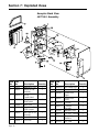
1
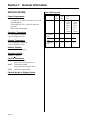
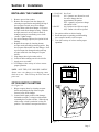
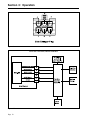
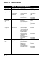
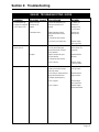
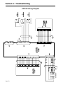
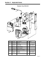
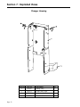
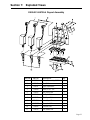
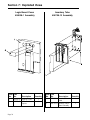
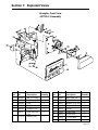
Coinco 9302-GX SERIES ELECTRONIC CHANGER Operation and Service Manual Table of Contents Section 1: General Information Introduction ............................................................................................................ 3 For Your Records .................................................................................................. 3 Features ................................................................................................................. 3 After Unpacking .................................................................................................... 3 Specifications ......................................................................................................... 4 Section 2: Installation Installing the Changer ............................................................................................ 5 Option Switch Setting ............................................................................................ 5 Section 3: Operation Coin Recognition .................................................................................................... 6 Coin Separation ...................................................................................................... 6 Rejected Coin ........................................................................................................ 6 Accepted Coin ....................................................................................................... 7 Credit & Accumulation .......................................................................................... 8 Vend ...................................................................................................................... 8 Coin Payout ........................................................................................................... 8 Change Storage ..................................................................................................... 9 Correct Change Operation..................................................................................... 9 Escrow Return ....................................................................................................... 9 Interface with Vendor/Controller .......................................................................... 9 Section 4: Maintenance Routine Maintenance ........................................................................................... 11 Removing/Replacing Individual Module Assemblies ........................................... 11 Cleaning ............................................................................................................... 11 Disassembling Payout Base................................................................................. 12 Clearing Coin Jams .............................................................................................. 12 Section 5: Bench Check Procedure Bench Check Procedure...................................................................................... 13 Tester Error Codes .............................................................................................. 16 Section 6: Troubleshooting Introduction .......................................................................................................... 17 Troubleshooting Guide ......................................................................................... 17 Wiring Diagram ................................................................................................... 20 Section 7: Exploded Views Modular View ...................................................................................................... 21 Changer Housing ................................................................................................. 22 9302-GX Payout Assembly ................................................................................. 23 Logic Board Cover Assembly ............................................................................. 24 Inventory Tube Assembly .................................................................................... 24 Acceptor Front View ........................................................................................... 25 Acceptor Back View ........................................................................................... 26 Page 2 Section 1: General Information INTRODUCTION AFTER UNPACKING FOR YOUR RECORDS If the coin changer is being stored or used as a spare, always keep it in its shipping carton when not in use. This will keep it clean and offer the best protection for the unit. This manual contains information on installing, operating and maintaining Coincos CoinPro 3, 9302-GX coin changer. This manual is intended for owners, route operators and shop-level technicians as a primary source of information. Taking time to read this manual and becoming familiar with this information will help you obtain the best performance from your Coinco CoinPro 3, 9302-GX coin changer. A label indicating the coin changer model number and serial number is affixed to the side of the coin changer. Refer to the model and serial number whenever you call upon your Coinco Service Center for information or service. The first four digits of the serial number contain the manufacturing date code which indicates the beginning of the warranty period. After unpacking the unit, inspect it for any possible shipping damage. If the unit is damaged, notify the shipping company immediately. Only the consignee (the person or company receiving the unit) can file a claim against the carrier for shipping damage. We recommend that you retain the original carton and packing materials to reuse if you need to transport or ship your changer in the future. EXAMPLE: Serial No. 269907053. First and second digits indicate week of manufacture. Third and fourth digits indicate year of manufacture. FEATURES · · · · · · · · · Accepts U.S. nickels, dimes, quarters and dollar coins. Pays out nickels, dimes and quarters from selfloading, high capacity change tubes. Change capacity of $40.55. Modular design for easy service. Select high or low quarter tube level by simply flipping a switch. Heavy-duty D.C. payout solenoids provide fast, accurate payout. State-of-the-art electronic logic system is designed for reliability and performance. Lightweight, rugged plastic construction provides dependable, maintenance-free service. Provides the fastest and most accurate coin acceptance of any electronic unit available today. Page 3 Section 1: General Information SPECIFICATIONS Coin Tube Capacity 5¢ tube Power Requirements · 34VDC · 3.6 Amp max. at 26VDC for 100 ms every 500 ms during payout · 750 m Amp max. for 1 second for each coin accepted · 200 m Amp. max standby Operating Temperature 0 to 150 Degrees Fahrenheit -18 to 65 Degrees Celsius Storage Temperature -22 to 160 Degrees Fahrenheit -30 to 72 Degrees Celsius Relative Humidity 20% to 98% Noncondensing Operating Attitude Vertical +3 degrees Physical Dimensions Height: 14.81 inches high (base to top of coin return lever Width: 5.28 inches in width (acceptor latch to acceptor latch Depth: 2.86 inches (gate closed) Physical Weight in Shipping Carton 4 pounds Page 4 Low Sensor Level Full Sensor Level Hand Load Level Figure 1 10¢ tube 25¢ tube LO 25¢ Option Switch Set To OFF Position LO 25¢ Option Switch Set To OFF Position 7 9 7 7 78 113 77 22 86 125 95 22 Section 2: Installation INSTALLING THE CHANGER 1. Remove power from vendor. 2. Remove the acceptor from the changer by releasing acceptor latches and pulling the top of the acceptor forward, away from changer. Unplug ribbon cable from changer. Free lower acceptor studs from changer housing. With the acceptor removed, set key holes in back of changer housing over mounting screw in the vendor. Tighten snugly. 3. Set desired changer options (See Option Switch Setting). 4. Replace the acceptor by inserting bottom acceptor studs into changer housing guides. Plug the acceptor ribbon cable into the changer. Press top of acceptor into changer housing until top acceptor studs lock into changer's acceptor latches. 5. Plug changer into 6-pin vendor socket. 6. Load coin tubes making sure all coins lie flat. 7. Apply power to vendor. 8. Test changer with a variety of coins to ensure proper operation. 1=USA/CAN Not Used 2=LO 25¢ ON: Quarters are directed to cash box once change tube has approximately 28 quarters OFF: Quarters are put into change tube until it is full. 3=$ACPT ON: Dollar coin will be accepted OFF: Dollar coin will be rejected 3. Set option switches to desired setting. 4. Return acceptor to operating position making sure acceptor latches secure acceptor. 5. Test with a variety of coins to ensure proper operation. NOTE: SAVE THE COIN CHANGER CARTON. Always store coin changer in its shipping carton when not in use. This will keep the unit clean and protected. OPTION SWITCH SETTING See Figure 2.0 1. Hinge acceptor down by releasing acceptor latches and pulling the top of the acceptor forward, away from changer. 2. Located in the upper portion of the changer, behind the acceptor, is a single switch module containing three rocker switches. When the top of the rocker switch is pushed in it is the ON position. The switches correspond as follows: Figure 2 Page 5 Section 3: Operation COIN RECOGNITION REJECTED COIN As a coin enters the changer through the acceptor funnel, its impact is absorbed by a white ceramic rail which debounces the coin and allows it to continue down the coin rail at a smooth and steady speed. As a coin rolls down the rail, it passes between two sets of LED sensors which measure the speed and size of the coin. The coin also passes between two sets of coils which measure the metallic content of the coin. These measurements are used to determine if the coin is valid and the value (denomination) of the coin. If a coin is rejected for any reason, both the UPPER (coin tube) and the LOWER (cash box) gate will remain closed. All rejected coins will drop into the vendor return cup via the coin changer coin return chute. See Figure 3 See Figure 4 COIN SEPARATION See Figure 3 After the coin's validity has been determined the coin rolls off the end of the coin rail and enters the separator section of the acceptor. The UPPER (coin tube) gate and the LOWER (cash box) gate are opened and closed by their respective solenoids. These solenoids are energized and de-energized by an electrical signal from the acceptor logic board based on the following criteria: the validity of the coin. the denomination of the coin. the status (full or empty) of the appropriate coin tube. The positions of these two gates cause the coin to be routed to one of three places: the appropriate changer coin tube, the vendor cash box, or if the coin is rejected, the vendor coin return cup. Figure 3 Page 6 Figure 4 Section 3: Operation ACCEPTED COIN See Figures 5 and 6 An accepted coin will be routed to either the vendor cash box or to one of the changer coin tubes. The (FULL) sensors in each coin tube determine which route the coin will take. If the coin tube corresponding to the validated coin is full (full sensor covered by coins in change tube), the cash box gate will open, allowing the coin to drop into the vendor Figure 5 cash box via the changer cash box chute. If the appropriate coin tube is not full (full sensor not covered by coins), the coin tube gate will open directing the coin down a ramp. Along the wall of the ramp are windows for entry into the coin tube. As the coin reaches a window of the appropriate size, it falls into the coin tube. All dollar coins are always directed to the cash box via the cash box chute. Figure 6 Page 7 Section 3: Operation CREDIT AND ACCUMULATION See Figure 7 There are two sensors, one in the separation section of the acceptor and one in the cash box path of the acceptor. As coins pass either one of these sensors, the changer sends credit information to the vendor electronic controller where the coin credit is accumulated. VEND Vend is a function of the vendor electronic controller. The vendor controller accumulates all credit information received from the coin changer. As credit is accumulated in the vendor controller, vend selections can be made when their respective vend price settings are equalled. COIN PAYOUT Coins are paid out from the coin changer when a change payback is required or when either of the coin changer inventory switches are manually operated. Coins are dispensed by D.C. solenoidoperated slides located at the bottom of each of the three coin tubes. The payout solenoids are controlled by signals generated by the vendor controller or the three inventory switches. Figure 7 When a solenoid energizes, the upward motion of its plunger compresses a spring and draws the solenoid lever, which in turn pushes a payout slide forward. This loads the coin for payout. When the solenoid de-energizes, the spring force returns the plunger to its de-energized state, which returns the solenoid lever and payout slide, dispensing a coin. Coin payout rate is determined by the vendor electronic controller board. Inventory Switches Located on the front of the coin changer is a nickel, dime and quarter inventory switch. These switches are used to manually remove coins from the changer coin tubes. They are disable while the vendor is in a vend cycle. Figure 8 Page 8 Section 3: Operation CHANGE STORAGE See Figure 8 The full tube sensors in each coin tube continually report the (full/not full) status to the coin changer logic board. The information is then used to determine the placement of the next accepted coin. This information controls the action of the acceptor coin tube and cash box gates. EXAMPLE: If the quarter tube is full (full sensor blocked by coins) the acceptor coin tube gate will remain closed and the cash box gate will open each time a quarter is accepted, routing all quarters to the vendor cash box via the changer coin chute. INTERFACE BETWEEN THE 9302-GX COIN CHANGER AND VENDOR / CONTROLLER See Figures 9 and 10 The 9302-GX changers interface connector is shown in Figure 9. Figure 10 shows the interface between the 9302-GX, vendor and electronic controller. After one or more quarters are paid out as change, leaving the full sensor exposed (not full), the acceptor coin tube gate will open each time a quarter is accepted, routing quarters to the changer coin tube until it is full again. NOTE: If the changer (LO$.25) option switch is set to the ON position, accepted quarters will be routed to the cash box when the (middle $.25 tube sensor) is blocked by coins. The low tube sensors in each coin tube continually report the (blocked/not blocked) coin level status to the vendor controller. This information is used to determine if change is available for payout. CORRECT CHANGE OPERATION The coin changer continually reports the status of the low tube sensors to the vendor's controller. The logic control for correct change is initiated by the vendor controller. ESCROW RETURN Escrow return is a function of the vendor electronic controller. Coins are always accepted regardless of the coin tube levels. The value of each coin is accumulated in the vendor controller. If a coin return is requested, a signal is sent to the appropriate payout solenoid(s) to pay back coins of the same denomination. If a dollar coin has been accepted, change will be returned in the least number of coins possible if an escrow return is requested. Page 9 Section 3: Operation Figure 9 9302-GX Controller/Vendor Interface Figure 10 Page 10 Section 4: Maintenance ROUTINE MAINTENANCE Routine maintenance will improve performance and extend the working life of the 9300 series changer and reduce the need for more involved repairs. Frequency of routine maintenance will depend on environment and number of transactions. The coin changer should be kept in its original shipping carton when not in use. This will keep the changer clean and provide the best protection for the unit. REMOVING/REPLACING INDIVIDUAL MODULE ASSEMBLIES Modular assembly replacement provides the basis of all 9300 series changer repair. Instructions for removing and replacing modules are provided below. These modules should be removed in the following sequence: Acceptor To remove the acceptor, raise the two acceptor latches and pull the top of acceptor forward and away from the changer housing. Unplug acceptor ribbon cable from main logic board. Raise acceptor and pull outward until the acceptor clears the housing slots. Coin Tube and Sensor Assembly Remove the logic board cover by inserting a straight tip screwdriver in the slot above the tube assembly. Twist the screwdriver to release the ccover. Unplug tube sensor ribbon cable from logic board. Spread the lower part of the housing slightly and pullout on tube assembly. To separate the coin tube assembly from the tube sensor board assembly, place the assembly face down. While freeing the four locking tabs, pull up on tube sensor board. Be careful not to damage sensors on logic board. Main Logic Board Assembly Unplug payout solenoids, and main harness assembly from logic board. Lift logic board out of housing. Payout Assembly With payout solenoids disconnected from main logic board, remove the four screws - two from each sideat the bottom of the housing. Separate payout assembly from changer housing by releasing cash box chute locking tab on back of changer housing and pulling downward on payout assembly. CLEANING Your 9302-GX changer is made of a high-quality industrial grade plastic which should only be cleaned with a warm water and mild detergent solution. CAUTION: Never submerge changer in water. Do not use petroleum solvents, steel wool, scouring pads, or a metal brush for cleaning. Do not spray any part of changer with any type of lubricant. Since all coins share a common coin ramp, heavy usage or a dirty environment can result in dirt build up. To clean the coin ramp, lift the acceptor gate upward and diagonally to the right. Hold gate firmly to prevent it from snapping back. Wipe the exposed coin ramp and inner surface with a damp cloth. For excessively dirty units, use a damp cloth with a mild detergent. NOTE: Do not submerge in water. For detailed cleaning of the acceptor, remove the front cover by pulling out and down of the front cover. Now remove the back cover by pushing in on two locking tabs on the side of the acceptor. To remove the coin sorting rail, snap the coin sense coils from the sorting rail and the cash box exit, being careful not to break coil wires. Free coil wires from the clip on the sorting rail. Now from the front of the acceptor, in area exposed by removing the front cover, locate the three locking tabs which secure the sorting rail. Using a small straight tip screwdriver, free the three locking tabs and remove sorting rail. See Figure 11. Page 11 Section 4: Maintenance DISASSEMBLING PAYOUT BASE FOR CLEANING Remove the four Phillips head screws from the bottom plate. Remove bottom plate and individual slides. Clean parts with mild detergent and hot water as desired. DO NOT SUBMERGE SOLENOIDS IN WATER. Replace slides making sure part numbers face up into changer. With the slides correctly seated on plunger tabs, reinstall the bottom plate, securing with bottom screws. Reinstall payout module into changer, securing with side screws. CLEARING COIN JAMS Figure 11 Should a coin jam occur in the cash box chute area, use the following steps to help dislodge coins: 1. Remove changer from vendor. 2. Keeping changer in an upright position, insert a narrow screwdriver into cash box chute or reject chute from bottom of changer to relieve jam. Access holes are also provided at the rear of the changer housing to help relieve coin jam. CAUTION: Excessive screwdriver pressure or twisting can cause permanent damage to the coin changer. Page 12 Section 5: Bench Check Procedure BENCH CHECK PROCEDURE FOR MODEL 9302-GX Using Coinco Tester #407341 NOTE: This tester is a static sensitive device and must be used in a grounded work station. PROCEDURE RESULT FUNCTION VERIFIED Set changer Coin Control Option switches as follows: #1: (OFF) Not Used. #2: (OFF) HI $.25 change tube. #3: (OFF) No $ coin accept Plug changer into tester. Set tester power switch ON. The digital display and tube sensors upper and lower LED's sequence, then the display will read rSt Power Up - Reset Set the changer Enable/Disable switch to the Disable (down) position and insert (1) nickel, (1) dime and (1) quarter All coins are rejected. Digital display reads r.05, r.10, r.25 for respective coins when rejected Coin reject (blocker function) Set the changer Enable/Disable switch to the Enable (up) position and insert (1) nickel, (1) dime and (1) quarter Coins are accepted, and directed to the respective changer coin tube, digital display will read: t.05 when nickel is deposited t.10 when dimes is deposited t.25 when quarter is deposited Coin accept (accepted function) Actuate Changer Reset Switch Digital display will read rSt NOTE: If reset switch is held in, the changer's communication software revision will be displayed.(Sr2) When the reset switch is released, display will read rSt Reset Randomly insert (9) nickels, (11) dimes, and (9) quarters Coins are accepted and directed to changer coin tube, digital display will read t.05, t.10, t.25 for respective coin when the 9th, 11th & 9th coin respectively is inserted, the low tube sensor LED will light. Example: When the 9th nickel is accepted, the digital display will read t.05 and the lower tube sensor LED will illuminate. Coin accept Low change tube sensors Page 13 Section 5: Bench Check Procedure BENCH CHECK PROCEDURE PROCEDURE RESULT FUNCTION VERIFIED Turn tester power OFF. Remove acceptor from changer. Block the coin change high tube sensors by completely filling tubes with coins or by inserting a rolled up tube of paper into the three coin tubes. Replace acceptor, turn tester power switch on and insert (1) nickel, (1) dime and (1) quarter Upon power up, the digital display and tube sensors upper and lower LED's sequence. Coins are accepted and directed to cash box, digital display will read b.05, b.10, b.25 respectively and tube sensors upper and lower LED's will illuminate High Tube Sensor Insert (1) $ coin $ coin is rejected No $ accept switch Insert a Canadian nickel, dime Coin is rejected quarter coin switch U.S. coins only or Set changer coin control option switches as follows: #1: (ON) Not Used. #2: (ON) Lo $.25 Change tube #3: (ON) $ coin accept Actuate changer reset switch Digital display will read rSt Insert (1) $ coin Coin is accepted and directed to cash box, the digital display will read b1.00 Block the middle $.25 change tube tube sensor without blocking the high tube sensor by partially filling $.25 change tube with coins (approx. $5.00) or by inserting a rolled up tube of paper far enough into $.25 change tube past the high sensor but far enough into tube to block the middle sensor. Insert (1) quarter. Quarter is accepted and directed to the cash box. The digital display will read b.25 and the upper and lower tube sensor LED's will illuminate Page 14 Middle $.25 tube sensor Section 5: Bench Check Procedure BENCH CHECK PROCEDURE PROCEDURE RESULT FUNCTION VERIFIED Actuate changer coin return lever Digital display will read ESC Escrow return Manually operate each of the changer's "Inventory" switches until all coins are dispensed. P.10, P.25 respectively. Each dispensing solenoid will energize, dispensing a coin, digital display will read P.05, NOTE: If lower tube sensors are covered, the lower tube sensor LED will illuminate, if both upper and lower tube sensors are blocked, both upper and lower tube sensors LED's will illuminate. Manual dispense ($.05, $.10, $.25) Actuate the 5-10-25 inventory control switches The digital display will read n, d, P respectively and number of coins payed out I.E. n 03 for 3 nickels, p 03 for 3 quarters and d 03 for 3 dimes. Pay out If all of these procedures can be successfully completed, the changer is operating properly. Set Coin Control Option Switches as desired. Set price(s) in vendor. Page 15 Section 5: Bench Check Procedure TESTER ERROR CODES ACPT - Acceptor Unplugged This error occurs when the changer does not communicate with the acceptor. CCO - Changer Communication Error This error occurs when the communication lines between the changer and tester are not present (changer not plugged in), broken or excessive noise exists on the line. RoCh - ROM Check Sum This error occurs when the changer's rom is defective. The following is a list of error codes the changer tester will display via the digital display: NoCr - No Credit This error will occur if a coin is accepted, but not detected leaving the acceptor. tUbE - Tube Sensor This error exists when the changer's upper tube sensor is blocked, while the lower tube sensor is not. NOTE: This error appears only during activity pertaining to the defective tube. I.E. during inventory or payout. 2Ar - Double Arrival This error occurs if a second coin is detected within 1/2 second of the first coin accepted, or within 2 seconds if first coin was detected as a slug. Page 16 ROUT - Routing Error This error occurs if a coin passes by the wrong outlet sensor. CoJA - Coin Jam Error This error occurs when a coin is detected in the validation coil for too long a time. SLUG - Non-Valid Coin Type This message occurs when the changer does not recognize the coin. Section 6: Troubleshooting INTRODUCTION The Troubleshooting Guide on the following pages is intended to help locate problems within the coin changer. If a changer cannot be repaired by following the guide, return the changer to the nearest Coinco Service Center for repair. If it is necessary to return the changer to Coinco, please accompany the changer with a brief description of the malfunction to help expedite the repair and return of the changer. The vendor electronic controller board is in constant communication with the 9302-GX coin changer. The electronic controller board not only supplies operating voltage to the coin changer but is largely responsible for the operation and function of the coin changer. (Refer to Section 3, Figure 10) Logic troubleshooting minimizes time spent in removing and replacing modules that are not defective. Some failures are caused by minor problems such as loose or faulty connections. Please check the following before replacing any parts: Connectors are inserted correctly. Connector pins are not bent or broken. All wires are properly secured. Inventory tubes are filled to their correct levels. NOTE: The following Troubleshooting Guide is based on the fact that the tester or vendor, with which the defective changer is being tested, functions properly when used with a known good changer. This guide is not intended to cover all failures, but to cover the most common failures. 9302-GX TROUBLESHOOTING GUIDE TROUBLE POSSIBLE CAUSE PROCEDURE REMEDY No coin acceptance No power Make sure changer is plugged into vendor Plug changer into vendor Acceptor Check power/blocker LED behind acceptor. If LED is ON, replace acceptor with good acceptor and test. If changer funtions properly . . . Replace acceptor If still no coin acceptance . . . Replace changer main power harness If still no coin acceptance . . . Replace changer main power harness If power/blocker LED is off, check to see that acceptor cable and changer power harness are properly connected to changer main logic board Plug acceptor cable and/or changer power harness into changer main logic board If still no coin acceptance . . . Replace changer main logic board If still no coin acceptance Replace changer main power harness Page 17 Section 6: Troubleshooting 9302-GX TROUBLESHOOTING GUIDE TROUBLE POSSIBLE CAUSE PROCEDURE REMEDY No coin acceptance or rejects percentage of good coins Coin return lever Make sure changer is mounted correctly and coin return lever is in proper position Reposition changer and/or vendor coin return lever. Acceptor is dirty or foreign matter in coin accept path Check to see that acceptor coin path is clean and free of foreign matter Clean acceptor and remove any foreign matter. If still rejects good coins . . . Replace acceptor If still rejects good coins . . . Replace changer main logic board Replace acceptor with good acceptor and test. If changer functions properly . . . Replace defective acceptor If still no/erratic credit Replace changer main logic board If still no/erratic credit . . . Replace changer main power harness Check the sensor board for loose or broken components. Make sure tube sensor board is properly secured to the tube assembly. Check cable from sensor board for damage or improper connection Replace tube sensor board If coin still goes to cash box, replace acceptor with good acceptor and test. If changer functions properly . . . Replace acceptor If coin still goes to cash box . . . Replace changer main logic board Coin tube gate in open position Remove acceptor back cover, check solenoid for free operation . . . Replace acceptor Tube sensor board Replace tube sensor board with good tube sensor board and test. If changer functions properly . . . Replace tube sensor board If coins still go to coin tubes . . . Replace changer main logic board Accepts coins but gives no/or erratic credit Accepted coins always go to cash box Accepted coins always go to coin tubes Page 18 Acceptor Tube sensor board or acceptor Section 6: Troubleshooting 9302-GX TROUBLESHOOTING GUIDE TROUBLE POSSIBLE CAUSE PROCEDURE REMEDY Accepted quarters go to quarter coin tube when Lo-$.25 switch is ON Quarter coin tube has less than 22 quarters Check to see that quarter coin tube has a minimum of 22 quarters Fill quater coin tube with 22 quaters to cover Lo-$.25 sensor Tube sensor board Replace tube sensor board with good tube sensor board and test If changer functions properly . . . Replace tube sensor board If coins still go to quarter tube . . . Replace changer main logic board Coin return lever Make sure changer is mounted correctly and acceptor gate opens when vendor coin return lever is operated Reposition changer and/or vendor coin return lever Acceptor Replace acceptor with good acceptor and test If changer functions properly . . . Replace defective acceptor If still no escrow . . . Replace changer main logic board Make sure solenoid wires are properly connected to changer main logic board Plug solenoid wires into logic board If still no payout, replace solenoid with good solenoid and test If changer operates properly . .. Replace defective payout solenoid If still no payout . . . Rplace changer main logic board If still no payout . . . Replace changer main power harness Credits coins but does not escrow No payout Payout solenoid Page 19 Section 6: Troubleshooting 9302-GX Wiring Diagram Page 20 Section 7: Exploded Views Modular View 9302-GX Item No. Part No. 1 407007 2 Description Qty. Harness 1 407400-3 407400-2 Logic Board Logic Board 1 1 3 922331.7 Changer Housing 1 4 407978-4 Payout Assembly 1 5 406728-12 Inventory Tube Assembly 1 6 407755-2 407755-1 406789 Acceptor Acceptor Logic Bd Cover & Label Assy. 1 1 1 7 Note Gray Connector Black Connector Gray Connector Black Connector Page 21 Section 7: Exploded Views Changer Housing Item No. 1 Page 22 Part No. 922331.7 Description Housing (only) Qty. 1 2 902011-1 Acceptor Latch, Right 1 3 902010-1 Acceptor Latch, Left 1 4 909729 Label, Indentification 1 Section 7: Exploded Views 9302-GX 406739-4 Payout Assembly Item No. 1 Part No. 406607-4 Description Solenoid Assembly, 24VDC Qty. 3 2 909113 Pivot Shaft 1 3 909141 Upper Payout Base 1 4 909630 Screw, 6-32 x 3/16 6 5 909105 10¢ Payout Slide 1 6 909104 5¢ Payout Slide 1 7 909103 25¢ Payout Slide 1 8 909102-1 Lower Payout Base 1 9 345P4R7 Screw, 4 x 7/16 8 10 909106 Solenoid Lever 3 11 909135 Coin Return Liner 1 Page 23 Section 7: Exploded Views Logic Board Cover 408038-1 Assembly Item Part No. No. 1 2 Page 24 922332-3 910889-2 Inventory Tube 406728-12 Assembly Description Quantity Logic Bd. Cover Label, Switch Options 1 1 Item Part No. No. 1 909115-4 2 Description Inventory Tube Label 406728-12 Inventory Tube & Board Assembly Quantity 1 1 Section 7: Exploded Views Acceptor Front View 407755-2 Assembly Item Part No. No. 1 406184-2 Description Gate & Coil Assy. 2 406567 Gate Bd. Assy. LED 3 4 906596-1 909095-2 5 6 906606-1 906624 7 751S21X Item Part No. No. Description 1 8 9 906618 400-8 Spring, Oper. Lev. Nut, 8-32 Lock 1 1 Cover Front Cover Assy. 1 1 10 11 406611 345-4R5 Mainplate & Coil Assy. Screw, 4x5/16 PH 1 2 Operating Lever Screw, Gate Lever Pivot Retaining Ring 1 1 12 906616 Coin Rail 1 1 13 14 923995 924241 Acceptor Label CoinPro Decal 1 1 15 16 921625 923984 1/4 LED Labels Gate Core Foam 4 1 Quantity 1 Quantity Page 25 Section 7: Exploded Views Acceptor Back View 407755-2 Assembly Item Part No. No. 1 406611 Description Mainplate & Coils Quantity 1 2 406167 Plunger & Yoke Assembly 2 3 906619-2 Spring, Copper-plated 1 4 406619-1 Spring, Nickel-plated 1 5 909096-1 Back Cover 1 6 407506-23 Board Assembly 9300 Acceptor 1 7 406612 Rear Chute & Coil Assembly 1 8 9 909095-2 906596-1 Front Cover Cover Gate 1 1 Page 26 Item Part No. No. Description 10 11 906622-2 345S4R7 Pin, Diverter Pivot Screw, 4x7/16 PH 2 2 12 906600-1 Diverter Door, Upper 1 13 909092 Diverter Door, Lower 1 14 15 909853-1 406857-3 1 2 16 922609 Coin Rail Solenoid Assembly Mainplate Foam 17 406613-1 Coil Assy., Sensing 1 18 908845-1 Plug, Spring Retention 2 19 921624 PVC Foam 1 Quantity 1 Notes Page 27 COIN ACCEPTORS, INC. 300 Hunter Avenue St. Louis, MO 63124-2013 (314) 725-0100 or (800) 325-COIN Coinco Publication No. 925054 Rev. 1 8/00 Printed in the U.S.A.