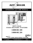
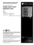
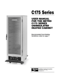
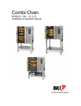
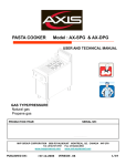
1
Operators and Service Manual
Product Holding Unit
U.S. Patent 6175099, 6262394
Other U.S. and Foreign Patents Pending
FWM3-23
FWM3-22
FWM3-24
FWM3-42
For information or technical assistance, call:
TOLL FREE
(800) 735-DUKE (3853)
or
(314) 231-1130
For information or technical assistance on the ICC Product Quality
Timer System, call:
(877) 422-8788
156931K
RESTAURANT
EQUIPMENT
MANUAL
PRODUCT HOLDING UNIT
TABLE OF CONTENTS
Manufacturer’s Introduction .......................................................................................................................................3
Specification Sheet......................................................................................................................................................4
Installation Instructions...............................................................................................................................................8
Stacking Units ..............................................................................................................................................................8
Unit to Unit Communication Connections .................................................................................................................9
Periodic Maintenance, Checklist And Cleaning Guide ...........................................................................................10
Troubleshooting.........................................................................................................................................................11
Electronic Control Fault Indications ........................................................................................................................11
Temperature Check Procedure.................................................................................................................................11
Control Programming................................................................................................................................................12
Parts Lists And Illustrations .....................................................................................................................................13
Wiring Schematic.......................................................................................................................................................15
Supplier Name:
Address:
Model #:
Manufacturer’s Introduction
The Duke Product Holding Unit was developed in
response to Burger Kings need for extended foodholding capabilities to provide consistently high,
“just cooked” food quality as part of the HIYW
kitchen.
The Duke Product Holding Unit utilizes Duke’s
patented “heat sink” holding technology that
provides even heat distribution to food pans through
the bottom and sides. This allows pre-cooked foods
to be held for extended periods without noticeable
degradation of quality, reducing food scrap/waste.
The self contained, individually formed, sealed
compartments of the Duke Product Holding Unit
eliminates food odor and taste transfer.
Because the compartments are sealed and formed to
the shape of the pan, no disassembly is required for
cleaning and product changes.
The unique design of the Duke Product Holding Unit
allows single temperature operation for all existing
product groups. This 190° F approved temperature
is preset at the factory. This reduces the likelihood
of inconsistent performance between Burger King
restaurant locations.
The Duke Product Holding Cabinet was also
designed to rethermalize food product. A thermostat
setting of 200° F minimum is required for
rethermalization. See instructions on page 12 for
thermostat adjustment.
NOTE: On.ly qualified
service persons should modify control temperature
presets.
REVISED:
Feb. 21, 2005
3 of 20
Duke Manufacturing Co.
2305 N. Broadway
St. Louis, MO 63102
FWM3-22-120
FWM3-22-208
FWM3-22-230
FWM3-22-240
FWM3-24-120
FWM3-24-208
FWM3-24-230
FWM3-24-240
FWM3-23-120
FWM3-23-208
FWM3-23-230
FWM3-23-240
FWM3-42-120
FWM3-42-208
FWM3-42-230
FWM3-42-240
Serial #:
Date Received:
Date Installed:
Telephone :
Fax:
Service Referral #:
Local Service
Name
(800) 735-DUKE (3853)
(314) 231-1130
(314) 231-5074
Local Service #
Installation requirements
Power Connection: See diagrams on pages
2-5.
!CAUTION!
Risk of fire or electric shock. Replace only
with Manufacturer’s cord set or equivalent.
U.S. Patent 6175099, 6262394
Other U.S. and Foreign Patents Pending
DUKE MANUFACTURING CO.
TOLL FREE 800-735-DUKE (3853)
314-231-1130
RESTAURANT
EQUIPMENT
MANUAL
PRODUCT HOLDING UNIT
Figure 1.1, FWM Specification Sheet
Model FWM3-22
Shipping Weight:
61 lbs/27.7 Kg
Electrical:
FWM3-22-120
FWM3-22-208
FWM3-22-230
FWM3-22-240
120 V, 6.7 A, 800 W, 50/60 Hz
208 V, 5.8 A, 1200 W, 50/60 Hz
230 V, 5.2 A, 1200 W, 50/60 Hz
240 V, 5.0 A, 1200 W, 50/60 Hz
U.S. Patent 6175099, 6262394
Other U.S. and Foreign Patents Pending
DUKE MANUFACTURING CO.
TOLL FREE 800-735-DUKE (3853)
314-231-1130
REVISED:
Feb. 21, 2005
4 of 20
RESTAURANT
EQUIPMENT
MANUAL
PRODUCT HOLDING UNIT
Figure 1.2, FWM Specification Sheet
Model FWM3-23
Shipping Weight:
83.5 lbs/37.9 Kg
Electrical:
FWM3-23-120
FWM3-23-208
FWM3-23-230
FWM3-23-240
120 V, 10.0 A, 1200 W, 50/60 Hz
208 V, 8.7 A, 1800 W, 50/60 Hz
230 V, 7.8 A, 1800 W, 50/60 Hz
240 V, 7.5 A, 1800 W, 50/60 Hz
P OWER
U.S. Patent 6175099, 6262394
Other U.S. and Foreign Patents Pending
DUKE MANUFACTURING CO.
TOLL FREE 800-735-DUKE (3853)
314-231-1130
REVISED:
Feb. 21, 2005
5 of 20
RESTAURANT
EQUIPMENT
MANUAL
PRODUCT HOLDING UNIT
Figure 1.3, FWM Specification Sheet
Model FWM3-24
Shipping Weight:
100 lbs/45 Kg
Electrical:
FWM3-24-120
FWM3-24-208
FWM3-24-230
FWM3-24-240
120 V, 13.3 A, 1600 W, 50/60 Hz
208 V, 11.5 A, 2400 W, 50/60 Hz
230 V, 10.4 A, 2400 W, 50/60 Hz
240 V, 10.0 A, 2400 W, 50/60 Hz
T OP S HELF
B OT TOM SHELF
P OWE R
U.S. Patent 6175099, 6262394
Other U.S. and Foreign Patents Pending
DUKE MANUFACTURING CO.
TOLL FREE 800-735-DUKE (3853)
314-231-1130
REVISED:
Feb. 21, 2005
6 of 20
RESTAURANT
EQUIPMENT
MANUAL
PRODUCT HOLDING UNIT
Figure 1.4, FWM Specification Sheet
Model FWM3-42
Shipping Weight:
100 lbs/45 Kg
Electrical:
FWM3-42-120
FWM3-42-208
FWM3-42-230
FWM3-42-240
120 V, 13.3 A, 1600 W, 50/60 Hz
208 V, 11.5 A, 2400 W, 50/60 Hz
230 V, 10.4 A, 2400 W, 50/60 Hz
240 V, 10.0 A, 2400 W, 50/60 Hz
U.S. Patent 6175099, 6262394
Other U.S. and Foreign Patents Pending
DUKE MANUFACTURING CO.
TOLL FREE 800-735-DUKE (3853)
314-231-1130
REVISED:
Feb. 21, 2005
7 of 20
RESTAURANT
EQUIPMENT
MANUAL
PRODUCT HOLDING UNIT
Installation Instructions
3.
1. Place holding unit onto stable surface.
2. Attach power supply cord to IEC 60320 C20
using approved cordset.
Follow instructions in the Operators Manual
PERIODIC MAINTENANCE, CHECKLIST AND
CLEANING GUIDE.
!CAUTION!
Risk of fire or electric shock. Replace cord with one of the following Duke
cordsets only:
P/N 156533 Cordset, NEMA 5-15P, 120 V
P/N 156811 Cordset, NEMA 5-20P, 120 V Canadian FWM3-24 & FWM3-42 units
P/N 156421 Cordset, NEMA 6-15P, 208/240 V
P/N 156400 Cordset, 230 V CE
Screw
The proper way to connect the power cord is to loosen the screw,
push the cord fully into the holder and then retighten the screw
Stacking Units
The FWM3-24 Product Holding Unit is designed to allow limited stacking capabilities. This section outlines how
to safely stack the holding cabinet.
Step
1
Step
2
Remove the base pan from all holding units, except for
bottom unit, that are to be stacked. The pan is held in
place by two screws on the bottom of the unit.
Place bottom unit into position then stack the next unit on top. The top
of the lower holding unit rests inside of the base of the upper unit.
WARNING!
TIP HAZARD! Do not stack FWM3-42
units. Do not exceed 3 holding units per
stack. Do not place holding unit stacks on
surfaces that may easily tip over.
U.S. Patent 6175099, 6262394
Other U.S. and Foreign Patents Pending
DUKE MANUFACTURING CO.
TOLL FREE 800-735-DUKE (3853)
314-231-1130
REVISED:
Feb. 21, 2005
8 of 20
RESTAURANT
EQUIPMENT
MANUAL
PRODUCT HOLDING UNIT
Unit to Unit Communication Connections
The following are the two different field connections, i.e. Specialty Board and Main Board.
Main Board Field Connection
The MB-1 Main Board Unit that has the ICC Black Box internally mounted can be identified as the warmer with
timer bars on both sides and plug connections numbered Warmer #2 and #3 as shown in Figure 2.1. This unit
is internally wired and ready to operate. Should your restaurant have two or more units on the main board the
second or third unit can be identified as the warmer with timer bars on each side and one plug connection as
shown in Figure 2.1. To put this second unit into operation connect the provided cable between the #2 plug
connection on the MB-1 and the single plug connection on the MB-2 unit. To put the third warmer into operation
connect the provided cable between the #3 plug connection on the MB1 and the single plug connection on the
MB2. The ICC steamer bar, if provided, plugs into the #3 plug connection on the MB1 unit as shown in figure
2.1. The program connection is used with the ICC provided Palm Pilot programming device.
Figure 2.1
Specialty Board Field Connection
The SB-1 Specialty Board Unit that has the ICC black box internally mounted can be identified as the warmer
with one timer bar and plug connections numbered Warmer #2 and #3 as shown in Figure 2.2. This unit is
internally wired and ready to operate. The SB-2 Specialty board Unit has one timer bar and one plug
connection as shown in Figure 2.2. To put this unit into operation connect the provided cable between the #2
plug connection on the SB-1 and the single plug connection on the SB-2 unit. The #3 plug on the SB1 is used if
a third SB2 warmer is added.. The program connection is used with the ICC provided Palm Pilot programming
device.
Figure 2.2
U.S. Patent 6175099, 6262394
Other U.S. and Foreign Patents Pending
DUKE MANUFACTURING CO.
TOLL FREE 800-735-DUKE (3853)
314-231-1130
REVISED:
Feb. 21, 2005
9 of 20
RESTAURANT
EQUIPMENT
MANUAL
PRODUCT HOLDING UNIT
Periodic Maintenance, Checklist And Cleaning Guide
DAILY
Opening Checklist
1. Ensure proper Pan Covers are inserted into the correct locations for fried and broiled products.
2. Place the Power Switch, located on the front of the Product Holding Unit, to the ON position.
3. Ensure both top and bottom HEAT Lights are illuminated.
4. Allow the Product Holding Unit to heat for at least 20 min. or until the HEAT Lights cycle off.
Operation Instructions/Adjustments
1. If the SERVICE Light illuminates during operation of the Product Holding Unit, discontinue use of
the affected shelf until the module is serviced.
2. Operate using Menu Bar as outlined in the Menu Scoreboard Operators Manual.
Closing Checklist
1. Turn power switch OFF.
2. Remove all pans and pan covers.
3. Allow to cool for approximately 30 minutes.
4. Clean Product Holding Unit as outline in the Daily Cleaning Instructions.
Cleaning Instructions
1. Wipe down the interior and exterior of the Product Holding Unit with warm water and mild detergent
using a soft cloth. Do not use excessive amounts of water.
2. Clean pans and pan covers using mild detergent and warm water. Ensure all soap is rinsed from
plastic pans and pan covers.
Caution!
Electrical shock hazard. Do not wash with water jet or hose.
Do not use caustic cleaners, acids, ammonia products or abrasive cleaners or
abrasive cloths. These can damage the stainless steel and plastic surfaces.
!Warning!
Bottom and sides of warmer wells are very hot and cool slowly.
U.S. Patent 6175099, 6262394
Other U.S. and Foreign Patents Pending
DUKE MANUFACTURING CO.
TOLL FREE 800-735-DUKE (3853)
314-231-1130
REVISED:
Feb. 21, 2005
10 of 20
RESTAURANT
EQUIPMENT
MANUAL
PRODUCT HOLDING UNIT
Troubleshooting
There are no user serviceable parts on the Duke Product Holding Unit. If a malfunction occurs, ensure unit is
plugged in then check all switches and circuit breakers. If the malfunction still exists, contact your Duke
Manufacturing Company authorized service agent or call 1-800-735-3853.
Electronic Control Fault Indications
The Service Light is located on the front of the control next to the heat light (see Figure 3). It provides an
indication to alert the operator to failures in the heater circuit. When a Service Light is on, the affected shelf
should not be used until the cause of the fault is corrected by a qualified service technician. The fault
conditions that could cause the control to turn the service light on are as follows:
1.
Over – Temperature Fault - An over-temperature
fault occurs when the control senses that the shelf
temperature is higher than the specified factory
preset temperature. This occurs when the power is
not removed from the heating element after the
shelf has achieved the preset temperature, causing
the control to turn on the service light. The auxiliary
thermostat prevents the temperature from
exceeding safe levels by regulating the temperature
to a maximum of 250° F.
2. Under – Temperature Fault - An undertemperature fault occurs when the control senses
that the shelf temperature is lower than the
specified factory preset temperature for more than
30 minutes continuously. This occurs when heating
element circuit opens or the RTD Feedback signal
is faulty, causing the control to turn on the service
light.
SERVICE LIGHT
THERMOCOUPLE
LOCATION
Figure 3
Temperature Check Procedure
1. A digital temperature meter that has been calibrated must be used to get an accurate temperature reading.
Use a thermocouple surface temperature probe to measure temperatures.
2. No pans should be in wells during the pre-heat and temperature check. Pre-heat the warmer for 30
minutes before taking any temperature readings. Do not take readings unless the cavity has been empty
for 30 minutes. This will allow the temperature to stabilize and will prevent false readings.
3. The warmer cavity should be cleaned and empty before the temperature is checked. Avoid any air drafts
that might flow through the cavity.
4. Locate the surface temperature probe on the bottom of the first cavity in the geometric center. The first
cavity is the one closest to the control panel (see Figure 3). Make sure the probe is making good contact
with the surface while taking readings.
5. All temperature controls exhibit a swing in temperature as the control cycles on and off while regulating to
the set point. The correct calibration temperature is the average of several readings taken over a period of
20 minutes after the warmer has been pre-heated. The average temperature should be ± 5°F from the set
point.
U.S. Patent 6175099, 6262394
Other U.S. and Foreign Patents Pending
DUKE MANUFACTURING CO.
TOLL FREE 800-735-DUKE (3853)
314-231-1130
REVISED:
Feb. 21, 2005
11 of 20
RESTAURANT
EQUIPMENT
MANUAL
PRODUCT HOLDING UNIT
Control Programming
The electronic temperature control is pre-set at the factory to maintain the temperature at the bottom
center of the pan cavity at 190° F +/- 5° F. This temperature is the result of many hours of food testing
at the Burger King test laboratory. There are no operator temperature adjustments that can be made.
Because the electronic control uses a platinum type RTD sensor, routine calibration is not required.
!DANGER!
LIVE ELECTRICAL COMPONENTS.
ONLY QUALIFIED SERVICE PERSONS SHOULD MODIFY CONTROL
TEMPERATURE PRESETS.
Temperature Programming
1. Remove cover from control side of the Holding
Unit and turn the Holding Unit on.
2. Locate the pushbutton S1 and S2 on the rear of
the control. (see Figure 4.1)
3. Press and hold S1 until any LED on the rear of
the control illuminates. (approximately 5
seconds)
4. Observe the front of the control (Figure 4.2).
Press and release S1 on the back of the control
until the desired light on the front of the control
flashes. (see Table 1)
FIGURE 4.1
Figure 4.1
NOTE: To comply with NSF sanitation requirements,
do not set the control preset temperature
below 190° F.
5. Press and release S2 until the sum of the LED
values illuminated on the rear of the board match
the desired pre-set temperature.
6. Repeat steps 4 and 5 for each pre-set
temperature then press and hold S1 until no LED
on the rear of the control is illuminated and the
lights on the front of the board no longer flash.
7. Replace cover on control side of the Holding
Unit.
Top Shelf
Bottom Shelf
Flashing Lights
A
B
X
X
TABLE 1
Figure 4.2
U.S. Patent 6175099, 6262394
Other U.S. and Foreign Patents Pending
DUKE MANUFACTURING CO.
TOLL FREE 800-735-DUKE (3853)
314-231-1130
REVISED:
Feb. 21, 2005
12 of 20
RESTAURANT
EQUIPMENT
MANUAL
PRODUCT HOLDING UNIT
Parts Lists and Illustrations
Qty Per Unit
Locator
2
3
4
5
6
7
8
10
11
12
13
14
15
16
17
18
19
20
21
22
P/N
600106
155749
156838
156316
155741
156616
156617
156059
156527
156485
156558
155849
156548
156285
156288
0653638
155750
156483
156539
156632
156540
156564
156301
156611
156565
156566
155752
156318
155755
155753
155680
155873
155876
156491
156533
156811
156421
156400
156938
Description
KIT, FWM CONTROLLER
TRANSFORMER 208/230CE/240 VAC
TRANSFORMER 230 VAC
TRANSFORMER 120 VAC
RECEPTACLE ELECTRIC
COUPLER 6X6 RJ12 (MB1 &SB1 UNITS ONLY)
COUPLER, 8X8 RJ45 (MB1 &SB1 UNITS ONLY)
CONNECTOR SPECIAL T (REAR VIEW MB2 & SB2)
SWITCH, LIGHTED, DPST, 16A
FACE PLATE WITH GASKET, FWM3-22
FACE PLATE WITH GASKET, FWM3-23
FACE PLATE WITH GASKET, FWM3-24
FACE PLATE WITH GASKET, FWM3-42
LATCH,PAN
SCREW SHOULDER
SCREW 1/4-20 X 3/4
RTD 1K OHM THIN
ELEMENT FOIL HEAT FWM3-22-120 & FWM3-42-120
ELEMENT FOIL HEAT FWM3-22-208 & FWM3-42-208
ELEMENT FOIL HEAT FWM3-22-230CE & FWM3-42-230CE
ELEMENT FOIL HEAT FWM3-22-240 & FWM3-42-240
ELEMENT FOIL HEAT FWM3-23-120
ELEMENT FOIL HEAT FWM3-23-208
ELEMENT FOIL HEAT FWM3-23-230CE
ELEMENT FOIL HEAT FWM3-23-240
ELEMENT FOIL HEAT FWM3-24-120
ELEMENT FOIL HEAT FWM3-24-208
ELEMENT FOIL HEAT FWM3-24-230CE
ELEMENT FOIL HEAT FWM3-24-240
THERMOSTAT AUXILIARY
NUT #8-32 KEPS
LID,FOODWARMER VENTED (FRIED)(GRAY)
LID,FOODWARMER SOLID (BROILED)(BLACK)
FWM3-22
FWM3-23
FWM3-24
FWM3-42
1
1
1
1
1
1
2
1
2
1
1
1
2
1
2
1
1
1
1
2
1
1
1
2
4
4
8
2
4
4
4
4
8
8
8
2
8
8
8
2
2
8
8
16
4
8
8
8
8
6
6
6
6
2
4
AR
AR
2
4
AR
AR
8
8
8
8
2
4
AR
AR
AR
1
AR
1
AR
1
4
8
AR
AR
AR
1
1
1
1
1
U.S. Patent 6175099, 6262394
Other U.S. and Foreign Patents Pending
DUKE MANUFACTURING CO.
TOLL FREE 800-735-DUKE (3853)
314-231-1130
13 of 20
1
2
1
1
1
2
CABLE, 8 FT, (FOR INTERCONNECTING UNITS)(NOT SHOWN)
CORDSET, NEMA 5-15P, 120V (NOT SHOWN)
CORDSET, NEMA 5-20P, 120V, CANADIAN FWM3-24,-42 (NOT SHOWN)
CORDSET, NEMA 6-15P, 208/240V (NOT SHOWN)
CORDSET, 230V CE (NOT SHOWN)
TERMINAL BLOCK
REVISED:
Feb. 21, 2005
1
RESTAURANT
EQUIPMENT
MANUAL
PRODUCT HOLDING UNIT
Parts Lists and Illustrations (Continued)
Rear View of MB1 & SB1
Rear View of MB2 & SB2
Figure 5, FWM Product Holding Unit Exploded View
U.S. Patent 6175099, 6262394
Other U.S. and Foreign Patents Pending
DUKE MANUFACTURING CO.
TOLL FREE 800-735-DUKE (3853)
314-231-1130
REVISED:
Feb. 21, 2005
14 of 20
RESTAURANT
EQUIPMENT
MANUAL
PRODUCT HOLDING UNIT
Wiring Schematics
Figure 6, FWM Internal Wiring Schematic
U.S. Patent 6175099, 6262394
Other U.S. and Foreign Patents Pending
DUKE MANUFACTURING CO.
TOLL FREE 800-735-DUKE (3853)
314-231-1130
REVISED:
Feb. 21, 2005
15 of 20
RESTAURANT
EQUIPMENT
MANUAL
PRODUCT HOLDING UNIT
Wiring Schematics (Continued)
Figure 7.1, MB1 Interface Cable Schematic
Figure 7.2, SB1 Interface Cable Schematic
Figure 7.3, MB2 & SB2 Interface Cable Schematic
U.S. Patent 6175099, 6262394
Other U.S. and Foreign Patents Pending
DUKE MANUFACTURING CO.
TOLL FREE 800-735-DUKE (3853)
314-231-1130
REVISED:
Feb. 21, 2005
16 of 20
RESTAURANT
EQUIPMENT
MANUAL
PRODUCT HOLDING UNIT
FWM3-42 Wiring Schematics
Figure 7.4 FWM 3-42 MB1 Interface Cable Schematic
Figure 7.5 FWM 3-42 SB1 Interface Cable Schematic
U.S. Patent 6175099, 6262394
Other U.S. and Foreign Patents Pending
DUKE MANUFACTURING CO.
TOLL FREE 800-735-DUKE (3853)
314-231-1130
REVISED:
Feb. 21, 2005
17 of 20
RESTAURANT
EQUIPMENT
MANUAL
PRODUCT HOLDING UNIT
FWM3-42 Wiring Schematics (Continued)
Figure 7.6 FWM 3-42 MB2 & SB2 Interface Cable Schematic
U.S. Patent 6175099, 6262394
Other U.S. and Foreign Patents Pending
DUKE MANUFACTURING CO.
TOLL FREE 800-735-DUKE (3853)
314-231-1130
REVISED:
Feb. 21, 2005
18 of 20