1
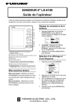
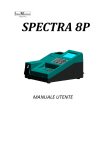
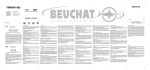
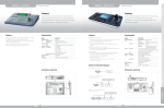
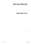
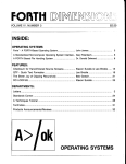
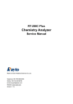
Maintenance and Repair Manual
Copyright:
RevA.1
1
Rayto L.L.C.
Rayto Electronics Inc.
Table of Contents
CHAPTER 1: INSTRUMENT OVERVIEW ...................................4
1.1 INSTALLATION ................................................. 4
1.1.1 Unpacking of the instrument ........................................................................................4
1.1.2 Select proper mounting location. ................................................................................5
1.1.3 Power source requirement ............................................................................................5
1.1.4 Connect the instrument to the power source .............................................................5
1.1.5 Connect to the external printer. ...................................................................................6
1.1.6 Adjust the display to a appropriate position .............................................................6
1.1.7 Place flowcell. .................................................................................................................6
1.2 STRUCTURE ..................................................... 8
1.2.1 Front view ........................................................................................................................8
1.2.2 Key Board .........................................................................................................................9
1.2.3 Back view........................................................................................................................10
1.2.Flowcell..............................................................................................................................10
1.3 INSTRUMENT
PARAMETER .......................................... 12
CHAPTER 2
FUNCTION DESCRIPTION............................. 13
2.1 RT-1904C
FUNCTION FRAME...................................... 13
2.2 DESCRIPTION
OF POWER SOURCE FUNCTION ............................ 13
2.3 MAIN
BOARD
FUNCTION DESCRIPTION ................................ 13
2.3.1Main board function illustration ................................................................................13
2.3.2Main board function diagram .....................................................................................14
2.3.3 Main board principle description. ............................................................................14
2.4 FRONT
BOARD
FUNCTION DESCRIPTION ............................... 15
2.4.1 Front board function illustration ...............................................................................15
2.4.2 Front board principle frame .......................................................................................16
2.4.3 Light filter selection and control ...............................................................................16
2.4.4 Liquid absorbing control of pump..............................................................................16
2.4.5 Temperature test and control ......................................................................................17
2.4.6 Light energy sampling and conversion ....................................................................17
2.4.7 Halogen tungsten lamp control..................................................................................17
2.5 PIPELINE FUNCTION DESCRIPTION.................................. 18
2
2.5.1Function illustration .....................................................................................................18
2.5.2 Pipeline structure..........................................................................................................18
2.6 LIGHT PATH FUNCTION DESCRIPTION ............................... 18
2.6.1 Function illustration ....................................................................................................18
2.6.2 Light path structure ......................................................................................................19
CHAPTER 3
FITTINGS REPLACEMENT ............................ 20
3.1 INSTRUMENT DISMANTLING METHOD.................................. 20
3.2 LAMP REPLACEMENT .............................................. 22
3.3 POWER SWITCH REPLACEMENT ...................................... 23
3.4 LIGHT FILTER REPLACEMENT ...................................... 24
3.5 CHANGE SIGNAL RECEIVER ........................................ 26
3.6 PIPELINE CHANGE ............................................... 28
CHAPTER 4
DAILY MAINTENANCE .................................. 31
4.1 GENERAL INTRODUCTION .......................................... 31
4.2 CLEAN
INSTRUMENT .............................................. 31
4.2.1 Clean outer surface of instrument.............................................................................31
4.2.2 Clean flowcell ................................................................................................................31
CHAPTER 5 COMMON MALFUNCTION LIST ................... 33
3
Chapter 1: Instrument Overview
RT-1904C is an internet-oriented chemistry analyzer, it can be used in the
measurement of the following matters:
Electrolytes
Substrates
Enzymes
Plasma proteins
Hormones
TDA‘S
It can program 160 test items. All the original program setting of tested items can be
revised by user.
It has double coloring system: One is flowcell system and the other is cuvette
system.
Following test methods can be provided:
Endpoint
Two point
Kinetics
Bichromatic
Absorbency
Multi- Calibration
It can analyze samples of blood serum, blood plasma, whole blood and urine etc.
It can connect to the internal network of hospital, quality supervision center and
Rayto user service center, and bring great convenience to the work.
Either built-in printer or external printer can be selected.
The external standard key board, CRT display, mouse and bar code scanners can be
choose to equip.
1.1 Installation
1.1.1 Unpacking of the instrument
Unpack the instrument and remove the materials used for delivery. Keep the packing boxes
and materials for repacking the instrument in the future.
1) Take the instrument out from the boxes.
2) Take away the packing materials, take out the instrument from the plastic packing
bags.
3) Check the articles in the packing box and confirm that the following articles are
contained::
RT-1904C mainframe
User’s manual
4
Packing list
Repair guarantee certificate of the agent
Power source line
1.1.2 Select proper mounting location.
The instrument should not be directly exposed to the sun.. The working table selected shall be
smooth in surface and has enough space to mount RT-1904C. The front edge of instrument shall be
close to the edge of working table. The working table is prevented to have great vibration(e.g.
centrifuge is placed on the table).
Note:
The working environment of the instrument:
The temperature shall be 15℃-32℃
The related humidity shall be20%-85%。
To ensure the normal operation of the instrument, it is forbidden to mount the instrument in
the following places:
A place with extreme change of temperatures.
A place too hot or too cold
A place with many dust
Close to electromagnetic equipment that can produce magnetic field.
1.1.3 Power source requirement
AC110V ~AC250V
50~60 Hz
80W
1.1.4 Connect the instrument to the power source
1) Insert one end of power source line to the power source socket of the instrument.
2) Insert the other end of power source line to the alternating current power source
socket.
Warning
5
● The alternating current shall have fine grounding ( zero
voltage<5V)。
● The alternating current shall be stable. It is forbidden to use
power source together with appliance with great voltage. It is
better to equip stable-voltage power source.
● If smoke, peculiar smell, or strange sound is found in the
instrument , turn off the power immediately and contact with
repair service center.
●When pulling out power source line, hold the connector plugs , do
not hold power source line.
1.1.5 Connect to the external printer.
1)
2)
3)
4)
5)
Confirm the printer and instrument are closed.
Insert the printing cable to the output port at back of the printer.
Fix the plug with the wire button that is used for fixup.
Insert the other end of printing cable into the RS-232 port of the instrument.
Connect the printer with alternating current power source with power source line
equipped in printer.
Note: RT-1904C can also use special built-in heat sensitive printer.
1.1.6 Adjust the display to a appropriate position
As indicated in the following drawing, move the LCD display screen to an appropriate
position deemed by you.(beware to impose proper strength).
Diagram 1-1 Adjust display screen
1.1.7 Place flowcell.
As indicated in the following drawing, take away the cover of flowcell (beware proper
6
strength is used)
Diagram 1-2 Open the cover of flowcell
1) Tear the adhesive tape use in fixing flowcell.
2) Remove packing materials
3) Place the flowcell into incubation carefully and make the aspirate tube in front。
Warning: Do not touch the surface of transmit window of flowcell to avoid
befouling of the transmit window with grease of hand and effect the absorbency.
7
1.2 Structure
1.2.1 Front view
①
⑤
②
③ ④
⑨
⑥ ⑦ ⑧
⑩
Diagram 1-3 Front view
①Lamp cover
The cover can be opened to replace lamp and perform pump maintenance.
②Flowcell Cover
Open this cover, cuvette can be used to do sample test.
③Aspirate tube
absorb the sample into the flowcell.
④Aspirate key
Push the key at test state, the instrument can automatically absorb the samples
into the flowcell.
⑤LCD display
Display colorful words or diagrams.
⑥Keyboard
Some common hot key. The printing and cleaning etc can be performed only
by one press of the key by operator.
⑦Right and left key
It is used together with mouse. Please refer to the “operation of mouse”221
RT-1904C Biochemistry Analyzer User’s Book
⑧Mouse
It can be used with mouse. Please refer to the “operation of mouse”221
RT-1904Biochemistry Analyzer User’s Book
⑨LED lamp
When the instrument is powered, the LED lamp is on.
⑩printer cover
Open the cover, the built-in printing paper can be placed.
8
1.2.2 Key Board
Diagram 1-4 Key Board
1)
key of soft key board:
*Push the key to open the soft key board. Push this
key again to close the soft key board..
2)
Rinse key:
3)
Print key:
* start or stop cleaning flowcell of the instrument
*Push this key to start printing immediately (it is
intended for built-in printer and invalid for external printer).
。
4)
a
Paper feeding key:
*Push the key to feed paper into the printer (it is
intended for built-in printer and invalid for external printer).
5)
lamp switch key :
*Switch on or off the lamp.
Left key:
*In
7)
Right key:
*Push the key to move rightward.
8)
Confirm key:
6)
the display menu, push the key to move
leftward.
key.
9
*At sample test, its function is equal to aspirate
1.2.3 Back view
图 1-5
① Power switch:
② Fuse:
③
④
⑤
⑥
⑦
AC INPUT:
Fan:
Printer port:
Mouse port:
RS-232 port:
Back view
To switch on or off the power source of the analyzer
Check fuse of instrument if there is no power supply after switch on the
power switch.
Power source line socket.
It is used in the cooling of instrument.
It is used to connect external printer.
It is used to connect external mouse.
Communicate with PC.
⑧ CRT port:
It is used for connecting the external CRT display.
⑨ Ke y_ B Stan dard ke yboa rd port: It is used in the external standard keyboard. If PS/2
port mouse is used, a patch cord is needed to equip.
⑩ Telephone line port: Connect telephone line for remote networking
⑩ DRAIN PORT:
waste out here.
1.2.Flowcell
Open the cover of flowcell as indicated in the following drawing.
Note: When opening the cover of flowcell or inner cover of light lamp, press the
two sides of cover so that it deform innerward ,and then open it according to the
direction of the following drawing.
10
Diagram 1-6 Opening the cover of flowcell
Inside the colorimetry system there are:
Incubation
Colorimetry bracket
Inner cover of light source
Flowcell
Inner cover of
light source
incubation
Flowcell
bracket
Diagram 1-7 Inside of colorimetry system
11
1.3 Instrument parameter
Linearity range
0.000-2.500A
Resolution
0.001Abs(display),0.0001 Abs(inner calculation)
Light source
halogen tungsten lamp,6V/10W,service life about 1000 hours
Wavelength
340,405,500,546,578,620,670nm ,One blank for optional filter
excursion
0.003A/30min
semi-bandwidth
<10nm
Temperature control
Room temperature,25,30,37℃ (Peltier component),precision±0.1℃
Flowcell
30μl quartz flowcell
Sample
volume
feeding
200-3000μl (add 50μl)
Cuvette
12.5mm×12.5mm square test tube
Cross pollution
≤1%(500μl)
Storage
160test items,500 test results
Port
Mouse,RS232,CRT,RSTN,Keyboard,Printer
Display
7″color LCD display(640×240line),256color
Print
Built in or external universal printer
Computer
Embedded high speed processor
Working
environment
15℃-32℃;Maximum humidity85%R.H.(below30℃)
Storage environment
-20℃-50℃; maximum 85%R.H.(below 30℃)
Weight
10kg
Dimension
450mm(L)×330mm(W)×140mm(H)
Fuse
250V, 3.15A
Power supply
110VAC-250VAC±10%,50-60Hz
12
,≤1.5%(300μl)
Chapter 2
Function Description
2.1 RT-1904C function frame
Refer to the following.
2.2 Description of power source function
The power used by the RT-1904C machine is provided by electric source module. The high
frequency PWM conversion technology is adopted so that the electric power has the advantage of
small size, light weight, high efficiency, high reliability, high load adjustment ratio and power
adjustment ratio etc. Two stage conversion is adopted in the power structure. One stage is single
reverse current AC/DC conversion , the other is DC/DC Buck converter, so that the direct
power exported from 4 passages had high voltage precision and adjustment rate.
The power source module exports 4 direct current , the power usage situation is as the following:
It is used in light filter generator , pump generator, Peltier temperature
CH1: +12V/3.3A
rise/fall and fan generator.
+5V/2.6A
It
is used in the main board and front board logic control
CH2:
It is used in tungsten halogen lamp
CH3: +5V/2A
It is used in embedded printer.
CH4: +5V/3A
Ch5:
+6V/0.8A
It is used in peltier temperature rise/fall.
2.3 Main board Function Description
2.3.1Main board function illustration
1. It acts as system platform and provide operating environment for system software and
application software.
2. It provides connection port with front end system, perform the control of front end
system and data collection and processing;
It provides I/O port of the system. Component that supports the I/O ports are as the follows:
four RS232 port that used respectively in the embedded serial port mouse, embedded serial printer,
embedded modem and outer RS232 port.1 parallel printer port ; one key board panel port; one
external XT compatible key board port; one embedded speaker port; one simulation telephone line
port; one 640×480 CRT display port, one 640×240 LCD display port.
13
2.3.2Main board function diagram
Frame
Memory
Local BUS
CRT
Interface
KeyPad
Interface
SH7709
HD64461
RS232
PORT
TTL level
232 port
FLASH
MEMORY
&
DRAM
TL16C552
Socket
Modem
EPLD
control
logic
Amplifier
Parallel
printer
interface
Inside
Mouse
interface
Inside
serial port
printer
interface
XT
compatible
keyboard
Interface
LED
Display
Speak
Interface
Phone
Interface
Diagram 2-1 Main board function diagram
2.3.3 Main board principle description.
As indicated in the above diagram, the main board is consists of the following major part:
1. SH7709、Flash Memory and DRAM constitute the basic platform of system operation; the
system software and application software is fixed in the Flash Memory. The address space of
Flash Memory is distributed in the 0 district of system storage area. The address space of
DRAM is distributed in the lower 32M space of 3 district of system storage area. The outer
frequency of CPU is 20MHz. When the system starts, the program is directly executed on Flash
Memory; the start area program on Flash Memory can complete upgrading of software.
2. HD64461、Frame Memory constitute the outer controller of the system, that mainly used in
support CRT and LCD display. The address space of Frame Memory is distributed in the high
32M 3 district of system storage area, and connects directly with HD64461. HD64461 supports
the port with SH7709, color/single color STN-LCD port, CRT(VESA VGA)port and UART
that is compatible with standard 16550. In the system the display port of HD64461 is
connected with LCD or CRT display , through UART it constitute one serial port of TTL
electric level and connected with serial port of Socket Modem so as to provide remote
maintenance ability for the system.
3. Serial communication port and parallel ports
There is 4 serial communication ports and one parallel port on main board: the serial port 2 on
SH7709 constitute RS232 for outer use; the PB port on HD64461 constitute TTL electric level
14
serial ports to connect with modem; through the expansion of TL16C55 chip, another two
serial ports and one parallel ports is provided by the system; one serial port is used in
connecting embedded mouse, the other serial port is used in connecting of embedded printer;
the expanded parallel port is used in connecting external parallel printer.
4. The transmission rate of Socket Modem module data is14.4K bits, it support At command bank,
connect with TTL serial port on HD64461, it connected outer simulation telephone line for use
in support the remote diagnosis, maintenance and upgrading of the system.
5. Programmable logic equipment
The programmable logic part can complete logic control of various part of the system. Through
the equipment the XT compatible key board port and the LED indicator light port are expanded,
it provided transmission control of disconnected signal and control of local bus that connected
on the front end. And it produces the M signal for use in the STN-LCD display screen.
6. Key board scanning and voice signal amplifying
Key board scanning logic is constituted by low 4 area ofSH7709 PTC port, and low 4 area of
PTF ports to form a 4×4 key board scanning. SH7709 regularly give out from PTC ports the
signal to scan keyboard. The PTF port inspects the key push action, it is delivered by LM386
and amplify and export the voice signal given out by SH7709 and Socket Modem to speaker
port.
7. Power conversion circuit
The system power provides +5V power for main board. The main board need mixed power
supply of +5V and +3.3V. Therefore +5V to +3.3V power conversion of main board is needed.
2.4 Front board Function Description
2.4.1 Front board function illustration
The front board is under the control of main board of computer. The plate execute and
complete all the unique functions of the semi-automatic biochemical analyzer, it is the control
execution center of the semi-automatic biochemical analyzer. In the RT-1904C product of
semi-automatic biochemical analyze, the front board mainly complete the following functions:
Selection of light filter
pump rotation to absorb certain amount of liquid
Control of tungsten halogen lamp(switch on/off)
Transfer, amplify and sampling of light and electric signals
Temperature test and control
15
2.4.2 Front board principle frame
The front board principle frame is as follows:
1904C semi-automatic bio-chemical analyzer front end plate principle frame
Location Detection
Filter circuit
logic control
Logic control
Bus connected with back end plate
logic control
Filter step motor
Drive circuit
Peristaltic pump motor
Peristaltic pump
Step motor
Peltier temperature control
Peltier
Temperature test
Halogen tungsten
Halogen tungsten lamp logic control
Lamp
A/D conversion
Photoelectric receiving
and conversion circuit
Fig 2-2 Front board function diagram
2.4.3 Light filter selection and control
In the semi-automatic biochemical analyzer RT-1904C product,the categories of selected light
filter is as follows: 340nm﹑405nm﹑500nm﹑546nm、578nm、620nm、670nm totaled 7 kinds.
Different wavelength of light filter is needed for different test method. Place the entire filters evenly
on circumference of 8 hole round disk. The angle of neighboring two hole is 360/8=45°. The
remaining hole is preserved for adding unique wavelength filter in the future. The round disk is
rotated by step motor. When step motor rotates on different angles, different wavelength filters is
selected by the system. The model of step motor is UBD6N07D04AKNC. The reduction gear is
equipped in the motor to increase the rotation moment. The reduction gear is equipped together
with step motor 8254 OUT. After exporting filter and pulse, related filter is selected.
2.4.4 Liquid absorbing control of pump
In the semi-automatic biochemical analyzer RT-1904C,the instrument automatically absorbs
related amount of reagent according to the amount of liquid set by the test item. Similar with the
filter, the step motor is adopted to control precision amount of liquid absorbing. The control method
is similar to that of the filter step motor. When the step motor rotates different angel, the instrument
absorbs different amount of reagent. Since the moment is large when pump is absorbing and
rotating, the double stages step motor is selected. The model is 17HS1022. The double stage drive
of L297 and L298 control/drive chip are adopted in related circuit drive.
16
Since the test sample is different and have different density, it can offer different absorbing rate
to users. 1~8 rates are set on pump. Different frequency division is written on Timer/Count of
82C54. OUT0 exports different frequency, the pump rotates in different rates.
2.4.5 Temperature test and control
Temperature control can be divided into temperature test and temperature rise/fall. The bus all
digital temperature sensors DS1820 produced by DALLAS that can decrease peripheral conversion
circuit is adopted in temperature test.
2.4.6 Light energy sampling and conversion
The sampling test of light energy is the core of semi-automatic biochemical analyzer. All the
test and calculation of semi-automatic biochemical analyzer are performed through test on light
intensity. Therefore the light energy sampling shall be precise and stable so that the requirement of
instruments on sampling test speed can be satisfied. The photoelectric sensor OPT301M of B-B
Company is adopted. The component integrates the silicon photovoltaic cell and embedded
calculation amplifier.
The silicon photovoltaic cell transfers the photocurrent signal into low
voltage signal. The embedded calculation amplifier amplifies the low voltage so as to satisfy the
measurement requirement of voltage. OPT301M has the strong point of high integration and fine
performance. at the same time only by transferring the voltage signal into digital amount to
CPU can it start processing. So A/D transfer circuit shall be added. ADS774 of B-B company is
adopted as A/D converter, its main indexes are: 12Bit. All can satisfy requirements of instrument on
measuring range, precision and speed. The voltage range of input A/D is 0-10V.
2.4.7 Halogen tungsten lamp control
To lengthen the service life of the lamp, the instrument shall automatically shut the lamp if
instrument does not measure after being on for a long time. The lamp used by the instrument is
halogen tungsten lamp. Its specification is 6V/10W. Both the current passes and voltage are
high .If voltage MOS tube is adopted to control on/off of halogen tungsten lamp, voltage drop of
the voltage MOS tube is great, the voltage consumption is also great, many disadvantages such as
heat emission will be brought along. So the small relay is adopted to control. The voltage drop of
relay contact is almost zero. And the voltage of relay line package is small. Control signal is put
out by PB.6 of 8255. Audion is used to drive on/off of line package that control relay.
17
2.5 Pipeline Function Description
2.5.1Function illustration
In instrument measurement, aspirate key is pushed, system control drive the rotation of
pump generator. The pinch wheel of pump presses the pipeline and enable the tested liquid in
pipeline extrude to liquid drainage port. The tested liquid is absorbed into the flowcell. When
sample volume set by measuring item is absorbed, the system control stops the pump generator.
Liquid to be tested is in the flowcell for measurement. After measurement, the system control drive
the rotation of pump generator, emptying the tested liquid in flowcell to decrease cross pollution
and ready for the next measurement.
2.5.2 Pipeline structure
Diagram 2-3 Pipeline Structure
2.6 Light Path Function Description
2.6.1 Function illustration
The optical structure of RT-1904C is, as the above diagram, spectrums structure after going
through light filter. After lightening tungsten halogen lamp, radiate light with filament as center is
given out. The radiate light is converted to parallel ray after going through convex. The protection
glass plays the role of protecting convex. After the parallel ray shoots the flowcell with sample
liquid to be tested, a part of light energy is absorbed by liquid. Light that shoot up is called shoot-up
light. The shoot-up light is changed to single color light after going through single color filter. The
single color ray shoots on the photoelectric receiver. The photoelectric receiver transfer the light
signal into electric signal and input it to front board for processing. The color of filter and color of
tested liquid shall be additive complementary colors.
18
2.6.2 Light path structure
Diagram 2-4 Light path sketch map
①.lamp
②.Protection glass
③.Convex
④.flowcell
⑤.filter
⑥.signal receiving assembly
19
Chapter 3
Fittings Replacement
3.1 Instrument Dismantling Method
RT-1904C is a high precision and complicated instrument. There is no component inside that can
be repaired by users. In case the instrument fails and cannot be solved on above method, specialists
will be sent for to repair. When it is determined that inner parts of instrument has broken down and
repair is needed, please dismantle the instrument according to the following procedures:
1)Thoroughly drain out the remaining liquids in pipeline of the instrument, fix the flowcell.
2)Turn off the power switches of instrument and printer respectively, pull out electric source
line.
3)Dismantle printer cable with screwdriver.
Pull out external mouse, connection line of modem, and other cables connected to the
Screws (7)
analyzer.
Diagram 3-1 The location of screw used for connecting upper and lower covers.
4)Place silk on a clean and smooth table, reverse the instrument on the silk to prevent
damage to outer surface of plastic cover of the instrument.。
5)Use screwdriver to unscrew seven screws used in connecting metal base and plastic upper
cover according to the above diagram.
6)Carefully place the instrument on the table, open the light source cover, take out the
aspirate tube from the fix hole on upper plastic cover, dismantle the flowcell also, and
place them in a safe place.
7)Dismantle first the embedded printer cover, flowcell cover, pump cover. Hold the front
side of upper plastic cover with both hands; carefully lift the upper plastic cover. Notice
20
that the upper and lower covers are connected with many groups of cable. Prevent
excessive force that damages plug and sockets for cable connection. If separation of upper
and lower covers is needed, the connection cable shall be pulled out from the socket. The
sketch map after separation of upper and lower covers is as the following:
Diagram 2-2 Sketch map after the upper and lower covers is separated.
21
3.2 Lamp Replacement
④
The structure of light source lamp is as the drawing:
②
①
③
①.fix screw. Its function is to fix the lamp on light path..
②、③.adjustment screws. Its function is to micro adjust the location of lamp in order to adjust the
intensity of light.。
④.power source line for lamp. It can supply power for the lamp.
1. Turn off the machine, open the inner cover, pull out power source line of lamp, unscrew the
bolt①,take out the light source lamp.
2. Place a new lamp on the light source seat, screw the bolt①,but do not screw it too firm,
connect the lamp power source line.
3. Screw the bolts ②、③ ,but do not screw it too firm
4. Open the machine and enter the main menu, select“ABS”option; after entry, set wavelength as
340nm and num of point as240,absorb distilled water to test.
22
5. Move frontwards and backwards the location of the lamp to maximize the tested AD
value.(value in the small bracket.e.g.3000)
6. Adjust bolts②、③,notice that the movement of ②、③ will lead to reverse effect to the AD
value. Find out the right bolt which enable the tested AD value to about 3000(1600—3000 also
permissible )
,and then fasten it.
7. Fasten bolt①,and place the cover of the lamp.
3.3 Power Switch Replacement
1. Turn off the machine, unscrew the bolts on base of instrument; take out the upper cover of
instrument.
2. Pull out plugs①、②、③(diagram -1)。
3. Press firmly the flip plate④ on both end of switch, push outwards the entire switch seat and
remove the switch seat(diagram-1)
4. Pull out tie-in of power source line⑤、⑥ with switch. Press firmly the flip plate and push
outwards the switch.(diagram-1)
。
5. Take a fine quality switch,the Ⅰon the switch faces the power source line socket, press in the
switch.
6. Connect the tie-in of power source line⑤、⑥and switch.(diagram-1)。
7. Press the switch socket outwards into the base of instrument(diagrram-2),the power source line
socket shall face the fan.(diagram-2)。
8. Connected power source line①、②、③(diagram-1)
。
9. Place the upper cover, firmly screw bolts. Open the machine (note that various connection line
do not press on the bolt port to prevent damage of connection line.)。
23
Diagram-1
③ ⑤ ⑥
⑤
①
⑥
Diagram-2
②
④
Power source line socket
fan
3.4 Light Filter Replacement
1、 Open the upper cover of RT-1904C,beware of the connection lines between upper cover and
main board.
2、 Unscrew the fix bolt of light filter cassette .
Filter cassette
Fix screw
24
3、 As indicated in the drawing, draw out anti dazzling screen, at the same time unscrew3 screws
on the filter wheel..
anti dazzling screen
3 screws
4、Unscrew the fix screw and dismantle the step motor.
5、First draw out step motor and take out filter wheel as indicated in the drawing.
Unscrew the fix screw
25
6 The taken out filter wheel is as the drawings:
670nm
546nm
340nm
fix copper ring
Gap
7、 Filter with various wavelengths is show in the drawing. The gap related wavelength is
340nm,the wavelength 340nm~670n mare arranged clockwise.
8、 Carefully take out fixing copper ring, take out used light filter.
Take out copper ring
Take out
used
filter
9、Replace new filter with related wavelength, fix it with cooper ring. And the replacement is
completed.
10、Reverse the above dismantling procedure, then the filter can be place in the anti dazzling
screen cassette .
3.5 Change Signal Receiver
The function of signal receiver is to change the varying light signal into the electric signal
and then calculated and process. It is the most important component in the light path system .The
change method is as follows.
26
1、After remove upper cover of RT-1904C,the signal receiving cassette can be seen (left side the
step motor).
Casstte
2、Unscrew screws, remove the cassette, the signal receiver plate can be seen.
White mat
signal receiver plate
screw with red mat
3、Unscrew 3 screws with red mat, draw outwards the receiver plate and the whole assembly can be
seen.
Signal receiving end
Power source line
4、Replace new signal receiving assembly, connects power source line, screw the screws, add mat
and equip with cassette. Thus the replacement is finished.
5、Connect the other end of power source line in the 4pin and 2pin plugs of front board. The signal
receiver can work normally.
4pin plug
27
3.6 Pipeline Change
1、Change of aspirate tube.
Hold the coarse side of flowcell. Carefully pull out the aspirate tube from the sample feeding
port of flowcell. And replace it with a new one.(Refer to diagram-1)
diagram-1
aspirate tube
2、Change of transfer tube:
Hold the coarse surface of flowcell, pull out the transfer tube from the liquid draining port,
pull out another end on the pump, and equip with new transfer tube.(refer to drawing-2)
Drawing-2
Transfer tube
aspirate tube
Note:carefully perform the above operations, do not let water drop on main board..
28
3、Pump replacement:
The whole view of pump is as following:
Clip button
Adjustment screw
Clip bar
Pump body
Pump tube
Generator
Copper column
The copper column is used to fix the pump on the RT-1904Cbase.
1、 Unscrew the adjustment screw and break off the clip button and clip bar.
Clip bar
2、 Open clip button, the pump tube can be seen.
Clip button
Pump tube
29
3、 Take out the pump tube, tear the belt, then the pump tube can be removed from the white cuff.
belt
White cuff
4、 Replace a new pump tube, tie the belt, operate reservedly so that the replacement can be
completed. At last adjustment firmness with adjustment screw.
30
Chapter 4
Daily Maintenance
4.1 General Introduction
RT-1904C is a clinic precision analyzer. To keep the instrument in a fine state, daily
maintenance shall be performed. The maintenance of RT-1904C is very simple, but it shall be done
earnestly and carefully.
4.2 Clean instrument
4.2.1 Clean outer surface of instrument.
● Keep clean the working environment of instrument.
● Neutral detergent and wet cloth wiping are needed in cleaning the surface of
equipment.
● Use soft cloth to clean the liquid crystal display.
Warning: Do not let any solvent, grease or eroded matter to contact the
instrument.
4.2.2 Clean flowcell
The clean of flowcell shall be kept so as to ensure the accuracy and reliability of test results.
1. Outer flowcell clean
a、According to the requirement to place flowcell.(refer to1.1.7)。
b、If the outer flowcell is polluted, take a soft cloth soaked with water to clean it softly.
2. Inside flowcell clean
a. Put vessel with distilled water under the aspirate tube, push RINSE key to start
continuous cleaning function. Push RINSE key again to stop cleaning. Generally the
cleaning takes half a minute.
b. The detergent of glass vessel or NACLO, (0.1N)、tween 20 diluted liquid
(2-3drop/L) are used to clean flowcell. Push RINSEkey to absorb the detergent,
again push RINSEkey to stop the rotation of pump. Let the detergent to settle in
flowcell for 5 minutes. At last continuous clean it for 1 minute by distilled water. If
it cannot be cleaned with once cleaning, detergent can be used to clean for a second
time.
The flowcell shall be cleaned in the following circumstances.:
The water blank difference is too large when open the machine.
31
Transfer test items.
Before closing the machine.
Warning:Do not let reaction liquid or other pollutant in the flowcell for a long
time.
32
Chapter 5 Common Malfunction List
Malfunction
Settlement
time pop up randomly, date can not be
stored after change.
Battery used out,replace another battery.
Check whether the D2、D3 beside battery is damaged,
replace it.
Water blank value is not stable, it is high
and negative value
Bubble is liable to be absorbed in the flowcell. The flowcell
is dirty ,clean the flowcell with 5%NaClO for several times
and clean it with distilled water.
Sample feeding tube is break; replace it.
Signal receiving assembly is damaged, replace it.
Air is absorbed in the first machine opening, switch off the
machine and absorbed again the distilled water.
Great absorbency differences
It is because that air is absorbed, absorb again distilled water.
Change for new distilled water
There is air in the pipelines, re-connect or change pipeline.
The light intensity of lamp is low, change lamp.
The flowcell is damaged, change the flowcell ,
The flowcell has not been insert to the bottom.
There are no factors; factor does not been input in the kinetic
method. Standard has not been set in end-point method and
two points method, or the standard was set but haven’t get
the factor in the calibration..
The parameter is not right, re-input is needed.
There is bubble or defilement in flowcell. Do it again after
cleaning.
The light filter is aging, replace light filter
Check whether the front board, Signal receiver are damaged,.
The aspirate volume is too low, increase the volume .
The reaction liquid is polluted.
There is dirt in light path, blow with ear absorb ball or
dismantle light path to clean(use lens wiping paper)
The lamp is in the wrong location, make re –adjustment
Check whether the lamp and light filter are aging, change if
there is any.
No test results
The test is not accurate, there is great
deviations in results.
Low light intensity
Blank screen and break down when start
the machine
33
The switch fails, change the switch.
Power source fails(import to J3 must be 5V,J10 must be
5V、6V、0V,J11must be 12V、5V、0V)replace it.
The software is damaged, upgrade the software.
Disorder screen
Historical data item cannot be entered.
Temperature control fails
The pump do not rotate, give out noise,
and do not absorb liquid.
It is reported that “please check whether
the filter wheel is in normal operation.”
The small drop-out line (old machine) is damaged, replace it.
Check chip of main board (7709),FLASH chip,9735chip。
Replace the damaged ones.
Check whether the FLASH chip on the main board is
damaged, replace it if there is any
LCD display line is in poor contact, pull out or re-plug in or
use glue. (old machine)
Check whether the FLASH ROM chip on mainboard is
damage. Change it if there is any.
In front board J11,J8plug has poor contact , pull out and
replace it.
U10 is invalid welding or damaged, re-welding or replace it.
The peltier is damaged(it shall be 4 ohm in empty load)
change it.
The pump value and receiver plate value doesn’t adjusted
after upgrading. Re-enter the pump value and receiver plate
value
Check the 4M crystal vibration on front board is damaged,
change it if there is any damage.
The sleeve of light sensor of receiver end newly replace is
too long, use scissors to shear it .
Check if the positioning light coupling is damaged, replace
the positioning light coupling.
Check whether the L297,L298,5804LB on the front board
is damaged or not,change it if there is any.
Appear 4095
Newly replaced filter, add attenuation plate or adjust position
of lamp.
The filter wheel does not rotate in place, use philips driver to
fix the filter wheel, check the fix light coupling, adjust
position of light coupling or replace it
the report can not be printed.
Reset related printer in system configuration, pull out plug or
replace it.
Print cable and change printer.
The analyzer can not starts.
Check whether the instrument is power on.
Check whether the power source plug is loosened.
Check the fuse
Check the voltage
Check whether the power source plug is loosened.
Check ON/OFF button
Check fuse
The printer cannot start.
34
The printer can not print
There is no liquid in flowcell.
The results has low repeat performance.
The absorbing volume of flowcell is not
constant.
The quality control is not in the range of
targeted value.
When break line and set standard in
end-point method,it is suggested that
“standard set error”
Temperature control time is too long.
Switch on RT-1904 first and then switch on printer.
Check whether the connection is in normal state.
Check whether the pump is in normal operation.
Check the connections of aspirate tube and flowcell port etc.
The aspirate tube is too long or too short.
The aspirate tube may be blocked and must be clean and
unblock it.
The flowcell is very dirty.
There is bubble in flowcell, and cleaning is needed.
Check the liquid absorbing of flowcell.
Aspirate tube inserts too deep into the flowcell, pull it out a
little.
Check whether the aspirate tube is blocked or not
The pump tube may need to replace.
Check the valid period of the reagent.
Check whether the setting is right or not and whether
parameter revision is needed
Ensure the quality control cannot be polluted.
Re-measure with another method.
Check the flowcell; use another reagent and re-measure.
Check whether standard material is absorbed correctly.
Please exit the standard setting procedure and enter, reset the
standard.
The normal work temperature range is 15℃-32℃
Note:If unsolvable error is found during the operation process or re-appear of
certain error, please contact the supplier.
Chapter 6
35
Common Fittings List
Common Fittings
36
Fitting Number
Light filter 340nm
1212
001
0
Light filter 405nm
1212
002
0
Light filter 500nm
1212
003
0
Light filter 546nm
1212
004
0
Light filter 578nm
1212
005
0
Light filter 620nm
1212
006
0
Light filter 670nm
1212
007
0
6V 10W halogen tungsten lamp
1212
009
0
Main board battery
1222
018
0
Signal receiving assembly
2100
003
1
Power upper cover
1211
040
0
Power base
1211
041
0
Power PCBA
2100
006
0
Front board
2100
001
0
Main board
2100
005
0
Key board plate
2100
004
0
Power switch (with socket)
1212
012
0
FLASH Rom
1110
072
0
LCD display
1212
015
0
LCD display cable
1213
003
0
Voltage inverter
1212
013
0
Peltier
1212
019
0
Trough light coupling
1190
004
0
Flowcell(two tube diameters)
1212
010
2
Lamp holder
lamp
Main board battery
Signal receiver
Power lower
cover
Power complete machine
Power PCBA plate
Power upper cover
Front board
37
Main board
Flash Rom
Power Switch assembly
LCD
Display cable
Main cable
Voltage inverter
B
38
Trough light
coupling
Note:
This manual may contain other ownership declaration and copyright
information. Its articles shall be observed and abided by. The information in the
manual may have inaccurate parts in technology and printing error.
The manual can be revised or upgraded without additional notice Rayto
company also can improve/revise the product/program described in the material at
any time without additional notice.
39