1
POLITEHNICA University of Timisoara
Computer Software and Engineering Department
Digital Signal Processing Laboratories – DSPLabs
2, V. Parvan Blvd., 1900 – Timisoara, ROMANIA
Tel/Fax: +40 56 192049
Web: http://dsplabs.utt.ro
Sponsored by
Mihai V. MICEA
Real-Time Data Acquisition and
Digital Signal Processing Systems:
Present and Prospects
Ph D R e p o r t # 1
Scientific Supervisor
Prof. Dr. Vladimir CRETU
2002
Mihai V. MICEA
Real-Time Data Acquisition and DSP Systems
Contents
1 Introduction
1
2 Digital Signal Acquisition and Processing Systems
5
2.1 Introduction ....................................................................................................... 5
2.2 General Description of DSAPS ......................................................................... 6
2.2.1 Data Acquisition Systems ..................................................................... 7
2.2.2 Digital Signal Processing Systems...................................................... 22
2.3 Common Architectures of DSAPS .................................................................. 28
2.3.1 Compact DSAPS................................................................................. 28
2.3.2 Modular DSAPS.................................................................................. 33
3 Applications of Data Acquisition and DSP
37
3.1 Application Domains of DSAP ....................................................................... 37
3.2 DSP-Based Digital Oscilloscope ..................................................................... 40
3.3 Real-Time Sonar Processing ........................................................................... 45
3.4 Real-Time Person Tracking Video System ..................................................... 50
4 High Performance Multiprocessor DSP Architectures
57
4.1 Motorola StarCore SC140 DSP Core .............................................................. 57
4.1.1 General Description ............................................................................ 57
4.1.2 Core Architecture ................................................................................ 58
4.1.3 SC140 Programming........................................................................... 65
4.2 Motorola MSC8101 Digital Signal Processor ................................................. 69
4.2.1 General Description ............................................................................ 69
4.2.2 MSC8101 Architecture ....................................................................... 70
4.2.3 Target Applications............................................................................. 73
4.3 Motorola MSC8102 Quad-Core DSP.............................................................. 75
Contents
5 Conclusions
79
References
85
i
Mihai V. MICEA
Real-Time Data Acquisition and DSP Systems
1 Introduction
Today society has a powerful ally – the digital computer. We are surrounded and
assisted in our everyday activities by this reliable and efficient friend, even when we
do not realize it immediately.
Currently, digital processing systems support almost every human activity, as
extremely efficient, fast and precise command and control tools. From bank
transactions and modern digital telecommunication services to air and ground traffic
control, or from quick and easy office management to the advanced technology of
satellites, digital control systems can be found as key components.
Moreover, digital technologies have recently approached one of the most
abstract and "human" field of activity: the art production.
This unprecedented development of digital systems and technology in our
present society represents the major premise of its accelerated progress.
Given the huge number of applications involving digital processing systems,
new types of problems emerged, including:
y interfacing the digital systems to the application environment
y developing efficient algorithms for data and signal processing
y embedding digital control and processing units into products
y providing real-time system operating capabilities
y designing effective data communication architectures and protocols
To address and solve such design and engineering challenges, new research and
development fields appeared:
1. Data Acquisition and Conditioning Systems
2. Digital Signal Processing
3. Embedded and Real-Time Systems
4. Digital Communication Architectures
and
Protocols
All major companies and laboratories involved in research and production of
digital equipment consider these fields as top priority and allocate a large amount of
highly qualified specialists and funding to approach the design and engineering
issues. Companies like Motorola, Alcatel, Siemens, Texas Instruments, Analog
Devices, Hewlett-Packard, Sun Microsystems, Intel, Microsoft, National Instruments,
Matrox, Tektronix, Math Works, Signalogic, Pentek and many others, prove the
importance of these fields.
On the other hand, the research and development efforts on these issues are
initiated and supported by the vast majority of universities and academic research
laboratories around the globe.
POLITEHNICA University of Timisoara is a good example, with its Digital
Signal Processing Laboratories – DSPLabs, which has operated for over 6 years in
design, analysis and engineering of data acquisition and conditioning systems, digital
signal processing, digital image processing and embedded systems.
Introduction
1
Real-Time Data Acquisition and DSP Systems
Mihai V. MICEA
DSPLabs is currently involved in close partnership with major national and
international companies, such as:
y Motorola, Incorporated – Semiconductor Products Sector. A major
collaboration program was initiated in 1999, to support didactic and research
and development activities at our department, in the digital signal processing
field.
y Alcatel Timisoara. The partnership, initiated in 2000, approaches the state of
the art in digital telecommunications field. A new course on this topic was
introduced in the computer software and engineering curricula, along with a
proper infrastructure for project development (diploma and master's thesis, as
well as project grants).
y Lasting Systems, Timisoara. As one of the closest and oldest partners of
DSPLabs, Lasting Systems supports many projects and didactic activities
involving data acquisition and conditioning systems, as well as modern
digital networking solutions.
y Academic Interdisciplinary Laboratory – "Computer Aided Modeling,
Testing and Monitoring of Electrical Machines – D109", with over 10 major
national research grants developed during 6 years of collaboration.
y Philips Research and Siemens VDO. Two new collaboration programs will
be initiated in the embedded systems research and development field.
Within this general framework, we are currently involved in a PhD program,
with a consistent support from Motorola SPS, since 2001. The PhD activity covers
the following topics:
1. Data Acquisition and Conditioning Systems
2. Parallel and Multiprocessor Data Processing Systems
3. Digital Signal Processing Techniques and Architectures
4. Real-Time and Embedded Architectures and their Programming
2
1.
As the number of digital processing applications increases continuously,
interfacing digital systems to their environment becomes a gradually difficult
design and implementation issue. For example, the current expansion of
multimedia systems requires digital acquisition, conditioning and processing of
audio and video signals, coming at high rates from the environment [1,2].
Therefore, proper data acquisition and conditioning systems must be
designed and developed, along with the corresponding hardware-software
infrastructures for reliable and fast data exchange.
Contributions to efficient design and analysis of high performance data
acquisition systems, as part of multimedia and digital telecommunication
applications with massive processing power and resource requirements, is one of
the author's objectives.
2.
Recent development of high performance multiprocessor and parallel processing
architectures at moderate costs opened large perspectives to system and
application developers.
Multiple-ALU processors like Motorola MSC8101, featuring up to 3000
RISC MIPS [3], or single-chip multiprocessors like Texas Instruments
Introduction
Mihai V. MICEA
Real-Time Data Acquisition and DSP Systems
TMS320C80 capable of over 2000 RISC MIPS [4], provide the application
designers with a tremendous processing power at effective costs.
As a result, parallel data structure and algorithm design and multiprocessor
programming techniques are highly emphasized in current computer and digital
control research activities.
Approaching the parallel and multiprocessor system design issues and the
specific programming techniques is another objective of our PhD research
activity.
3.
A continuously increasing number of real-life applications take advantage of the
great capabilities provided by digital signal processors for design and
implementation of digital processing and control systems [5, 6, 7]:
à High degree of instruction parallelism due to the modified Harvard
à
à
à
à
à
à
à
à
à
architecture and instruction pipelines and caches
Highly parallel instruction set
Specially designed arithmetic and logic unit(s), supporting single-cycle
complex operations (e.g. MAC – Multiply and Accumulate instructions)
Distinct Address Generation Units, operating in parallel with other chip
resources
On-chip ROM and RAM memory as well as efficient off-chip memory
expansion port
On-chip peripherals (timers, PLL module, serial interfaces, various host
interface ports)
On-chip coprocessors and controllers (e.g. memory controller, instruction
cache controller, DMA controller, filter coprocessors)
Hardware debugging support (JTAG Access Port)
Reduced power consumption
Low cost
Digital signal processing specific techniques and algorithms design and their
efficient implementation on high performance DSP platforms is still another
goal of our PhD research.
4.
Some of the most frequent real-life application targets are the embedded digital
processors and controllers with real-time operating requirements [8, 9, 10, 11].
Examples of embedded, real-time systems range from simple command and
control systems (e.g. automotive controllers, intensive care monitoring, flexible
manufacturing control and monitoring, instrumentation, computer peripheral
devices and user interfaces) to highly complex, distributed systems (such as air
traffic control networks, intelligent highways, flight control and avionics,
satellite and space station control, group of autonomous robots operating in
hazardous environments, multimedia and high speed communication systems).
Real-time operation requirements enforced by such applications make the
design and implementation of both their hardware and software subsystems a
difficult task.
These systems should not only be fast, but also should feature the following
characteristics:
Introduction
3
Real-Time Data Acquisition and DSP Systems
Mihai V. MICEA
à Execution timing is a priority: tasks missing their predefined start or stop
deadlines can cause serious damage to the system or to the environment
à Predictability is another key issue – the behavior of the system should be
predictable at any time and in any operating circumstances
à Correct operation with respect to timing constraints, assuming the worst
case execution conditions (e.g. system overload, various failures)
à Reliability: fault analysis is of high importance and efficient solutions
must be provided to guarantee that some critical tasks meet their
deadlines in presence of certain failures
Contributions to the development of efficient techniques for design and
analysis of real-time system and application software on embedded
architectures, is another topic of our PhD research.
This report focuses on the real-time data acquisition and digital signal
processing architectures, their design and implementation issues and the prospects in
this modern field of digital engineering.
The general architecture and the operating principles of digital signal acquisition
and processing systems (DSAPS) are given in the next section. Some of the most
common types of DSAPS found in real-life applications are discussed further on. As
the processing needs of most current applications (e.g. multimedia systems and realtime digital communication systems) grow continuously, design and implementation
of high performance DSAPS is a key issue. New techniques are required for design
of the system architecture, data communication hardware and protocols as well as for
real-time operating software. This topic is also approached in section 2 of the paper.
Section 3 discusses some of the most important digital signal acquisition and
processing applications developed by the author within recent research projects and
grants at national and international level. These projects approach various application
fields, such as laboratory instrumentation, testing and study of electrical machines,
analysis of fluid dynamics, SONAR systems, autonomous robots, digital audio
processing, digital image processing and recognition, and many others.
High performance digital signal processing platforms are currently the most
efficient solutions for embedded and real-time applications involving signal
acquisition and processing. Such an example of platform is the Motorola StarCore
digital signal processing core – an innovative parallel architecture providing
exceptional performance, efficient code development and execution, based on a
variable-length execution set (VLES), and low power consumption. Section 4
addresses the StarCore platform description along with the digital signal processors
developed with this core: Motorola MSC8101DSP and MSC8102DSP.
4
Introduction
Mihai V. MICEA
Real-Time Data Acquisition and DSP Systems
2 Digital Signal Acquisition and Processing Systems
2.1 Introduction
Currently, digital processing systems support almost every human activity, as
extremely efficient, fast and precise command and control tools. From bank
transactions and modern digital telecommunication services to air and ground traffic
control, or from quick and easy office management to the advanced technology of
satellites, digital control systems can be found as key components.
Given the huge number of applications involving digital processing systems,
new types of problems emerged, including:
y interfacing the digital systems to the application environment
y developing efficient algorithms for data and signal processing
y embedding digital control and processing units into products
y providing real-time system operating capabilities
y designing effective data communication architectures and protocols
Thus, a key problem is how digital systems interact with the environment in an
efficient manner. The general configuration of a digital signal processing system is
presented in Figure 2-1. Three main components appear, in close relationship with
each other [12, 13]:
y Environment, operating with continuous signals, like sound, light, movement,
pressure, fluid flow and so on;
y Digital Signal Processing System (DSP), operating with digital (discrete)
signals and data, and
y Data Acquisition and Conditioning System (DAQ), with the main function of
interfacing the analog (continuous) signals to the digital counterparts.
DSAPS
Environment
DAQ
Continuous signals
Digital Signal
Processing
System
Digital signals
Figure 2-1. General configuration of a digital signal processing system
Digital Signal Acquisition and Processing Systems
5
Real-Time Data Acquisition and DSP Systems
Mihai V. MICEA
The structure generally referred to as Digital Signal Acquisition and Processing
System (DSAPS) includes both the data acquisition block and the signal processing
unit [14, 15]. This section gives a detailed presentation of the internal architecture
and operating principles of DSAPS.
2.2 General Description of DSAPS
Digital signal acquisition and processing systems are found in a large number of reallife applications, including [1, 2, 7]:
y Computer aided engineering
y Technologic engineering
y Computer aided testing of equipment
y Industrial automation
y Robotics
y Digital telecommunications
y Computer aided laboratory instrumentation
y Multimedia systems
y Digital audio and video processing
y Artificial intelligence systems
y Movie production
y Show-business
Due to the large number and variety of application domains involving DSAPS,
the next section addresses this topic in detail, with some carefully selected examples.
As depicted in Figure 2-1, DSAPS provide two main components to solve (a)
the problem of interfacing continuous (analog) signals to digital data – the Data
Acquisition System (DAQ), and (b) the problem of processing the acquired data in
an efficient manner – the Digital Signal Processing (DSP) system.
The problem of interfacing signals can be further detailed as in Figure 2-2.
Transducers transform the analog signals (e.g. sound, light, movement, pressure,
fluid flow, biological signals, radar, sonar, seismic waves, audio/video
communication signals and many others) into electrical signals, which are further
transformed into digital with the analog-to-digital converters (ADC).
Environment
A/D and D/A
conversion
Transducers
Analogue
signals
Analogue
electrical
signals
DSP
system
Digital
signals
(binary codes)
Figure 2-2. Signal interface configuration
Figure 2-2 shows another important characteristic of DSAPS – the signal flow
between the DSP system and the environment is bidirectional [16, 17]:
6
Digital Signal Acquisition and Processing Systems
Mihai V. MICEA
Real-Time Data Acquisition and DSP Systems
(a) Data coming from the environment is acquired by the DSP for further analysis
and processing. This operation employs signal conversion from analog to digital
(Analog-to-Digital Conversion, ADC or A/D).
(b) The DSP system controls the environment according to its processing results.
Data flows from the DSP towards the environment, involving proper signal
conversion from digital to analog (Digital-to-Analog Conversion, DAC or D/A).
2.2.1 Data Acquisition Systems
DAQ systems are hybrid electronic devices (analog and digital) with the main role of
interfacing the digital signal processing systems to the environment [12, 18]. The key
functions of a DAQ system, briefly discussed in the following paragraphs, are:
(i) Signal conditioning
(ii) Analog-to-digital conversion (ADC)
(iii) Digital-to-analog
conversion
(DAC)
(iv) Digital I/O
(v) Data communication with the DSP system
(i) Signal conditioning
Non-electrical signals coming from the environment are transformed in
electrical signals (current and/or voltage) by transducers. Signal conditioning is
further necessary to adapt the output scale range of the transducers to the input
signal characteristics of the A/D converters. Programmable Gain Amplifiers
(PGA) are usually used to adjust the scale range of the input electrical signal
with a properly selected factor:
FSRACQ = APGA ⋅FSRIN
(2 .1)
where: FSRACQ is the scale range properly adjusted for signal acquisition, FSRIN
is the scale range of the input signal (with respect to the operating specifications
of the transducer), and APGA is the gain factor of the PGA. If APGA is less than 1,
the resulting signal is attenuated in fact.
In addition, a pre-filtering of the input signal is usually done. The maximum
sampling rate of signal acquisition is known a priori on each and every DAQ
system. On the other hand, Nyquist's Sampling Theorem [19, 20] states that, for
a correct and unique digital representation of sampled signals, the maximum
frequency of the analog input signal must be less than half the sampling rate:
1
f IN max < FS
(2 .2)
2
where: f IN max is the maximum frequency of the input signal and FS is the
sampling rate.
Therefore, the input signal is pre-filtered with a proper low-pass filter of
analog type (an RC-net circuit). This operation eliminates the signal aliasing
phenomenon [21, 22]. In applications with high level of noise, further filtering is
needed. For example, a common type of noise problem is the 50 Hz power line
noise. Post-filtering can be performed before signal conversion into digital
Digital Signal Acquisition and Processing Systems
7
Real-Time Data Acquisition and DSP Systems
Mihai V. MICEA
(using analog filter schemes) or with a digital filter algorithm (DSP-based) after
signal acquisition but before any other kind of processing.
(ii) Analog-to-digital conversion (ADC)
Analog to digital conversion of signals is one of the main goals of a data
acquisition system. A/D conversion is the set of operations that establish an
exact correspondence between an analog electrical value (current, voltage) and a
finite-length binary code [23].
ADC is a three-phase process (see Figure 2-3), all of them being currently
performed sequentially by a monolithic device – the analog-to-digital converter.
x(t)
D/A Conversion
Sampling
xs [n]
Quantization
x q[n]
Binary Coding
x[n]
Figure 2-3. Analog-to-digital conversion procedure
Periodic extraction of value samples from the input analog signal (x(t) in
Figure 2-3) is the first step of the A/D conversion – "sampling". In most cases
the sampling period is constant, TS. The resulting signal is a discrete-time signal
(xs[n] in figure above). As depicted in Figure 2-4, sampling establishes a direct
relation between the two independent time-variables, t (continuous-time) and n
(discrete-time):
t = n⋅TS , n ∈ Z
(2 .3)
Sampling is needed for practical reasons: the value of the signal at the input
of the quantization module must be constant while quantization is performed.
Consequently, the sampling period corresponds exactly to the quantization
period.
While the input analog signal x(t) is a continuous-time function with values
in a continuous domain, the sampled signal xs[n] is a discrete-time function. The
domain of values remains continuous for the sampled signal:
x(t ) : R → x min , x max ⊂ R
(2 .4)
min max
x s [n] : Z → x s , x s
⊂R
This is equivalent to saying that the two signals in (2 .4) are represented with an
infinite precision.
[
[
8
]
]
Digital Signal Acquisition and Processing Systems
Mihai V. MICEA
Real-Time Data Acquisition and DSP Systems
Sampling Module
xs [n] = x(n · TS )
x(t)
Analogue
signal
Discrete-time
signal
TS
x(t)
x s [n]
0
t
01 2 3 4 5 6 7 8
n
TS
Figure 2-4. Uniform sampling of signals
Quantization addresses the problem of finite-precision representation of
signal values, a problem common to all digital systems. After each sample value
is quantized, it will correspond to a discrete element in a finite set of values
(Figure 2-5).
x(t) : R → [x min, xmax ]
Sampling
(rate: TS )
x s [n] : Z → [x min , xmax ]
s
s
Quantization
and coding
x q [n] : Z → { xmin , x max }
q
q
Figure 2-5. Sampling, quantization and coding in terms of signal functions
The main parameter of the quantization step is the resolution of
representation (denoted here with b) of quantized signal samples xq[n].
Resolution means in the case of digital systems – the number of bits used to
{
}
represent all the values in the discrete set x qmin , x qmax . Further on, resolution b
gives the total number of values in the set (also called "quantization levels"):
L = 2b
(2 .5)
Figure 2-6 below details the quantization procedure for two consecutive
signal samples, xs[n] and xs[n+1].
Digital Signal Acquisition and Processing Systems
9
Real-Time Data Acquisition and DSP Systems
max
) cod L − 1
q
...
(x
Mihai V. MICEA
FSR
cod i + 1
∆
eq [n+1]
x s [n]
eq [n]
cod i
min
)
q
x s [n+1]
x q [n]
...
(x
x(t)
x q[n+1]
cod 0
n
n+1
T
S
Figure 2-6. Quatization of two consecutive signal samples
Quantization is further characterized by two additional parameters (see
Figure 2-6): Full Scale Range of the quantization, FSR (2 .6), and the
quantization step, or quantum (2 .7). The latter defines the minimum value of
the signal, sufficient to produce after quantization a binary code that differs with
its least significant bit from the previous result. Therefore, the quantum is also
called LSB (Least Significant Bit).
FSR = x qmax − x qmin
max
(2 .6)
min
FSR xq − x q
=
(2 .7)
≡ LSB
L −1
2b − 1
Quantization is a "many-to-one mapping" operation [19] and, therefore, it is
an irreversible process with loss of information. The amount of information lost
in the quantization process is modeled by the function named "quantization
error":
∆ ∆
eq [ ] : Z → − , ;
2 2
(2 .8)
eq [n] = x q [n] − x s [n]
∆=
Two consecutive samples of this discrete-variable function – the quantification
error, are depicted in Figure 2-6: eq[n] and eq[n+1].
The essential parameter of quantization is the resolution b. The larger the
value b, the better the quantization quality in particular, and the overall A/D
conversion, in general. As a result, with the growth of b:
à
à
à
à
10
the total number of quantization levels L, increases
the quantization step ∆, is smaller, though much more accurate
the quantization error eq[n], decreases, and
the approximation of the input sampled signal xs[n] by xq[n] is better.
Digital Signal Acquisition and Processing Systems
Mihai V. MICEA
Real-Time Data Acquisition and DSP Systems
The last step employed by the A/D conversion is binary coding. This
operation assigns a distinct code of b-bits length to each quantization level.
Therefore, the quantization resolution b also specifies the length of the resulting
binary code of the A/D conversion process.
There are many coding schemes used to map the quantization values into
binary codes. The most frequently used are presented in Table 2-1, Table 2-2
and Table 2-3 [24, 12].
Table 2-1. Unipolar Straight Binary (USB) coding scheme
Quantization level for xq[n]
xqmax[n]
(FSR)
xqmax[n] − 1 LSB
...
xqmin[n] + 1 LSB
xqmin[n]
(0)
Corresponding binary code
11...11
11...10
...
00...01
00...00
Table 2-2. Bipolar Offset Binary (BOB) coding scheme
Quantization level for xq[n]
xqmax[n]
(FSR / 2)
max
xq [n] − 1 LSB
...
+ 1 LSB
− 1 LSB
...
xqmin[n] + 1 LSB
xqmin[n]
(–FSR / 2)
Corresponding binary code
11...11
11...10
...
10...00
01...11
...
00...01
00...00
Table 2-3. Bipolar Two's Complement (BTC) coding scheme
Quantization level for xq[n]
xqmax[n]
(FSR / 2)
max
xq [n] − 1 LSB
...
+ 1 LSB
− 1 LSB
...
xqmin[n] + 1 LSB
xqmin[n]
(–FSR / 2)
Digital Signal Acquisition and Processing Systems
Corresponding binary code
01...11
01...10
...
00...00
11...11
...
10...01
10...00
11
Real-Time Data Acquisition and DSP Systems
Mihai V. MICEA
As seen in the tables above, the coding scheme to be used in a particular
application also depends on the type of input signal: bipolar signals (featuring
both positive and negative signal values) require appropriate coding schemes.
Bipolar two's complement (BTS) scheme (Table 2-3 above) is used more
frequently, as it matches data representation of most digital architectures.
The entire set of operations described above and employed by the A/D
conversion are currently executed by single, monolithic devices – the analog-todigital converters with sampling, or "sampling analog-to-digital converters"
(ADS) [25].
(iii) Digital-to-analog conversion (DAC)
Digital-to-analog conversion is the procedure reciprocal to ADC. With
digital-to-analog conversion, each binary code of b bits length at the input is
related to an electrical value (current or voltage).
Similarly to ADC, the D/A operation requires a well-defined interval to
perform the conversion: TD/A. This delay raises two issues: (a) what happens to
the output electrical signal during a conversion period and (b) how can the
resulting signal be shaped as close as possible to the desired contour of a natural,
continuous signal [19]. These problems are solved using on-chip output
interpolator logic. Figure 2-7 and Figure 2-8 present two simple versions of
signal interpolation: a zero-order hold DAC and a linear interpolation DAC.
x[n], x(t)
x[n]
0
1
2
3
4
5
6
7
8
x(t)
9
n, t
Figure 2-7. Zero-order hold D/A conversion
x[n], x(t)
x[n]
0
1
2
3
4
5
6
7
8
x(t)
9
n, t
Figure 2-8. D/A conversion with linear interpolation
12
Digital Signal Acquisition and Processing Systems
Mihai V. MICEA
Real-Time Data Acquisition and DSP Systems
In the previous figures, x[n] is the input digital signal and x(t) is the
resulting analog signal of D/A conversion. Increasing the speed of conversion
(thus reducing the TD/A period) is usually preferred to a complex interpolation
method.
(iv) Digital I/O
At present, many applications use digital signals directly, without any need
of A/D or D/A conversion. Some transducers transform the non-electric signals
from the environment into digital pulses. Mouse-like rotation transducers for
example, are based on wheels having small peripheral apertures that can block
or pass the light from a LED to a photo-diode. As a result, the transducer outputs
a digital impulse train to the processing system. Another example is the CCDbased optical sensors that provide the processing system with digital signals
indicating the presence (logic high) or absence (logic low) of light on a
particular dot of the sensor matrix.
In such cases the interface between transducers and the digital signal
processing system generally consists on buffering the I/O signals.
The most common digital I/O provided by the DAQ systems consists of
serial interface and data buffering.
(v) Data communication with the DSP system
An important problem related to DAQ systems is how data communication
with the DSP system is implemented and managed. Several aspects of the
communication problem can be stated as follows:
à Speed/data throughput. Major improvements of the communication speed
were performed in recent years due to the increasing number of
applications requiring high performance data manipulation and
processing (e.g. multimedia systems, top digital telecommunication
systems, and so on).
à Local/remote data link. Depending on the overall DSAPS architecture,
DAQ can be placed locally to the DSP (on the same board) or remotely.
Each type of approach requires specific communication techniques and
protocols.
à Simple communication protocols. Special care must be taken regarding
design and implementation of the communication interface in a simple
and efficient manner [26]. The interface should also match the
specifications and communication protocol of the DSP system which acts
usually as master.
à Standardization. In order to ensure system portability and modularity, the
communication interface must obey well defined standards, from its early
specification and design stages. Examples of standard communication
interfaces used in moderate-performance DSAPS are [27]: RS232 serial
interface, Centronix parallel port (SPP), Enhanced Parallel Port (EPP)
and Extended Capabilities Port (ECP).
Works [28] and [29] describe the design and implementation issues of
different types of communication interfaces, from a custom data link with a
Digital Signal Acquisition and Processing Systems
13
Real-Time Data Acquisition and DSP Systems
Mihai V. MICEA
DSP-based peripheral port, to some common serial and parallel communication
interface standards, respectively.
The general architecture of a data acquisition and conditioning system is
presented in Figure 2-9 [12].
Analogue signals
Analogue signals
...
...
ADCM
ADCM
...
Cmd
I
C
O
M
M
Data
I
O
M
DAQCDM
...
Analogue signals
...
Data
IBUS
Data
DACM
Cmd
DACM
Cmd
DAQ
System
...
Analogue signals
Figure 2-9. General architecture of a data acquisition system
As presented in the figure above, common data acquisition architectures feature
the following components:
y one or more analog-to-digital signal conversion modules (ADCM)
y one or more digital-to-analog signal conversion modules (DACM)
y digital I/O module (IOM)
y data acquisition command module (DAQCDM)
y internal bus for data, address and command lines (IBUS)
y communication interface with the controlling system (ICOMM).
The A/D conversion module (ADCM) performs function (ii) and optionally (i)
as described above, and it represents the key module of any DAQ system. Its main
device is the A/D converter (ADC), as shown in Figure 2-10 below. For
cost/performance reasons, a single ADCM block can process multiple analog input
signal lines (x0(t) .. xN–1(t), thus, a total of N input lines). The input signals are
properly conditioned either inside the ADCM or with a distinct signal conditioning
module directly connected to the transducers and to the ADCM as well.
In the case of multiple input signals the conditioning block (highlighted with
gray color in Figure 2-10) must include an analog multiplexing device (MUX) to
select a single input channel to the output at any time. Channel selection is controlled
by the DAQCDM block through the multiplexer selection lines and must be
synchronized with the signal sampling and A/D conversion operations. Therefore,
selection of a new input channel occurs at fixed time intervals, TS (sampling period).
14
Digital Signal Acquisition and Processing Systems
Mihai V. MICEA
Real-Time Data Acquisition and DSP Systems
ADS
(t)
Gain
Ctrl.
...
x
N– 1
Signal
conditioning
x0(t)
...
Analogue signals
ADCM
MUX
x i(t)
Input
Sel.
S&H
x iS[n]
S/H
x iq[n]
ADC
SCV
EOC
b
Control lines
Binary code
Figure 2-10. Analog-to-digital conversion module (ADCM)
Further on, the currently selected input signal, xi(t), is sampled with a "Sampleand-Hold" device (S&H), resulting the xis[n] signal. The input sample is then
quantized and binary coded into xiq[n] by the ADC. The resulting code is of b-bit
length, where b is the conversion resolution, as mentioned previously in this
subsection. Modern A/D converters include both the ADC logic and the S&H device,
thus being called "sampling A/D converters" or ADS [25].
ADCM operation is controlled through the following type of signals:
y Signal conditioning control lines, including Gain Control and multiplexer
Channel Selection
y S/ H , to sample the input signal or hold the current sample value during the
conversion
y SCV, to trigger a new signal conversion cycle on the ADC (ADS)
y EOC, conversion status line; high when the current conversion cycle finishes.
The D/A conversion module (DACM) has a symmetrical architecture to the
ADCM (Figure 2-11) and performs function (iii) described above.
Modern D/A converter devices incorporate all the necessary logic for proper
output signal generation (interpolation – zero-order hold or first-order linear) and for
easy connection to microprocessor-type of data, address and control buses (data
buffers/latches for input code, selection and enable input lines). The input data buffer
plays two main roles: (a) to store the input binary code codeIN, for the duration of the
D/A conversion till the next code to be converted is supplied, and (b) to implement
the zero-order hold interpolation technique, common to most of the D/A signal
conversion devices [30].
With the proper signal conditioning block, implemented as a component of the
DACM or as an external device, multiple output analog signals can be obtained, each
one of them correspondingly conditioned to the application needs
(amplification/attenuation, post-filtering, supplementary interpolation and so on).
Figure 2-11 also presents the minimum command signals necessary to operate
the DACM (EOC, SCV, Output channel selection, Gain controls – similar to the
ADCM).
Digital Signal Acquisition and Processing Systems
15
Real-Time Data Acquisition and DSP Systems
Mihai V. MICEA
EOC
Output
Sel.
SCV
Analogue signals
MUX
...
xOUT(t)
...
codeIN
Input
buffer
DAC
Signal
conditioning
DACM
Gain
Ctrl.
b
Binary code
Control lines
Figure 2-11. Digital-to-analog conversion module (DACM)
The operation control of all functional blocks composing the DAQ system is
performed by the DAQ command module (DAQCM). A typical DAQCM should
feature the following functions:
y address decoding for selection of each device of the system;
y provide the application programs on the host/controlling system with special
purpose data, command and status registers for flexible control of the
acquisition process;
y provide synchronization of system components with programmable
timer/counter logic;
y control the signal conditioning operations with appropriate circuits:
input/output channel selection to the multiplexers, signal range adjustments
(gain/attenuation) at the programmable gain amplifiers (PGA), etc.;
y interface the internal bus of the system (IBUS) to the corresponding devices
connected to it (e.g. buffer/latch registers, bus driver circuits, Three-State
logic);
y calibrate the analog devices involved in signal acquisition, in the case of high
performance DAQ systems.
Figure 2-12 exemplifies the time diagram of the command flow employed by
the DAQCM for signal acquisition with an ADCM block as described above. The
diagram considers a total of N analog input channels into the ADCM, out of which
only one is selected in a sequential manner by a multiplexer. Therefore, there are M
channel selection lines as inputs for the multiplexer (SEL0..M–1), where:
M = log 2 N
The command flow presented in Figure 2-12 describes the auto-triggered type
of signal acquisition, enabling the maximum acquisition rate the ADC device is
capable of. First, the ACQCM selects the input channel (channel i) for the next
acquisition process by properly asserting the SEL0..M–1 lines (SEL0..M–1 = i).
Consecutively, the "Sample" signal is asserted ( S/ H = "1") to acquire a sample
(xis[n]) from the input analog signal xi(t).
16
Digital Signal Acquisition and Processing Systems
Mihai V. MICEA
Real-Time Data Acquisition and DSP Systems
SEL
0..M−1
Channel i
Channel i+1
S/H
SCV
EOC
TA/D
DATA
x iq[n]
Figure 2-12. Example of a signal acquisition command flow
After sampling, the S/ H line is set low to hold the current sample value for the
A/D conversion cycle. Further on, the A/D conversion is started (SCV = "1"),
resulting in the EOC line pulled low by the ADC device to indicate the start of a new
conversion cycle. When the current A/D conversion completes (after the TA/D
period), the ADC asserts the EOC line to indicate the end of conversion.
The rising edge of the EOC signal can be used to trigger both the selection of
the next input channel (channel i + 1) and to fetch the result of the current
conversion, xiq[n], through the DATA bus.
To increase efficiency and to eliminate the specific delays of multiplexing, the
next channel can be selected consecutively to the "Hold" command, i.e. right after
the S/ H line is set low (see the dotted arrow in Figure 2-12). The multiplexing
delays that can be eliminated with this technique are: tA (access time), tSET (settling
time) and tPD (propagation delay) [12, 16, 31, 32].
This type of data acquisition – the auto-triggered type – has the advantage of
speed, employing the maximum conversion rate the ADC is capable of. Still, there is
an important drawback, to this approach: the acquisition period cannot be guaranteed
as constant and cannot be known exactly. All the ADC devices provide approximate
(typical values of) conversion timing specifications [16, 25]. On the other hand,
many applications require medium conversion speed but constant timing rather than
maximum speed. Moreover, conversion of a signal sample from the input is very
often triggered by the signal processing system that acts as master within the
DSAPS.
A solution to the problems stated above is to provide the DAQ system with
programmable timers to control the start of conversion cycles (i.e. the SCV signal is
issued from the timer output line). This type of acquisition can be called
programmed acquisition.
Another option is the DSP system to trigger and control directly the acquisition
process as needed – the on-demand acquisition.
An important issue regarding data acquisition is the communication of the DAQ
system with the DSP system (function (v) described above). The functional block of
Digital Signal Acquisition and Processing Systems
17
Real-Time Data Acquisition and DSP Systems
Mihai V. MICEA
the DAQ that implements the communication interface is the ICOMM module (see
Figure 2-9).
Data communication between the DAQ and the controlling system (DSP) solves
a two-folded issue: (a) to provide a proper hardware/software infrastructure for data
and command exchange and (b) to provide appropriate mechanisms for fetching the
acquisition results when ready into the DSP.
There is a wide range of standard communication interfaces currently available
for the ICOMM implementation, depending on the DSAPS system architecture and
on the application requirements. Table 2-4 synthesizes the most common types of
communication interface used for data/command exchange in DSAPS.
Table 2-4. Standard communication interfaces for DSAPS
Standard
RS-232
(TIA/EIA232-F)1
Type
Serial data
link
Performance
19,200 bps at 16.5 m
(115,200 bps max.)
RS-422
(TIA/EIA422-B)
Differential
serial data
link
RS-485
(TIA/EIA485-A)
Differential
serial data
link
10 Mbps (max.) at
13.2 m;
100 kbps at 132 m
(max.)
Same as above
USB
Universal
Serial Bus
FireWire
High speed
(IEEE 1394a) serial bus
18
10÷100 kbps (low
speed), 0.5÷10 Mbps
(medium speed),
25÷500 Mbps (high
speed);
5 m max. cable length
between peers
Up to 400 Mbps at
4.5 m cable length
Observations
Single-ended, point-to-point
interface.
Supports simplex, half-duplex
and full-duplex type channels
[33].
Multi-drop (multiple receiver
operation), balanced interface
[33].
Balanced interface, multipoint
operation, operation from a
single +5V supply, up to32
transceiver loads (unit loads)
[33].
Supports up to 127 physical
devices in a hierarchic
configuration.
2 data (differential signals) + 2
power lines.
Robust communication protocol
(CRC, error handling/recovery,
etc.) [34].
Tree-structured multipoint
configuration.
6 signal lines: 1 pair for
peripheral power + 2 pairs for
data transport.
Supports hot-swapping, plugand-play and automatic
configuration.
Three-layered communication
protocol, with isochronous
channels [35, 36].
Digital Signal Acquisition and Processing Systems
Mihai V. MICEA
Real-Time Data Acquisition and DSP Systems
IrDA
Infrared Data
Association
Up to 2 m length;
from 9600 bps up to
115200 bps; up to 4
Mbps (with PPM
encoding scheme) and
16 Mbps (with HHH
modulation code)
CAN
Controller
Area
Network
Up to 1 Mbps over 40
m cable length;
up to 5 kbps over
10000 m cable length
SPP/BPP
Standard
Parallel Port
/
Bidirectional
Parallel Port
Up to 150 kBps in the
forward direction
("Centronics" mode)
and 50 kBps in the
reverse direction
("nibble" and "byte"
modes), over a cable
length of up to 2 m
EPP/ECP
(IEEE 1284)2
Up to 2 MBps over
Enhanced
Parallel Port / max. 10 m cable
length
Extended
Capabilities
Port
Digital Signal Acquisition and Processing Systems
Point-to-point cordless serial
data link.
Asynchronous operation (9600 –
115200 bps), synchronous
operation (1.152 Mbps). Higher
transfer rates: synchronous with
special encoding/modulation
schemes.
CRC schemes provided by the
Physical Layer protocol.
1:n communication scheme for a
host with up to 8 peripherals
simultaneously.
Dynamic assignement and re-use
of peripheral addresses [37, 38,
39].
Two-wire differential serial bus.
Reliable operation in noisy
electrical environments.
Open architecure system with
user-definable transmission
medium [40].
Parallel communication link
with 8 data lines + 9
handshaking (4 outputs + 5
inputs, relatively to the host).
Most data transfer and
hanshaking protocol is
performed by software (e.g.
"nibble mode" needs 10 I/O
instructions for each byte of
data) [41].
Parallel link, downwards
compatible to SPP/BPP.
Handshaking handled by
dedicated hardware; data
transfer needs a single software
instruction.
This results in a 16- or 32-bit
data transfer interface using 8bit I/O hardware lines.
ECP protocol supports 16-byte
FIFO, DMA, RLE – run-length
encoding (ratios up to 64:1),
channel addressing and peer-topeer capability [41].
19
Real-Time Data Acquisition and DSP Systems
20
GPIB
(IEEE 488.1)
General
Purpose
Interface Bus
ISA-AT
Industry
Standard
Architecture
– Advanced
Technology
PCI
Peripheral
Component
Interconnect
PXI
PCI
eXtenstions
for Instrumentation
Mihai V. MICEA
20 m max. length;
up to 8 MBps with
HS488 protocol
8 bidirectional data + 3 control +
5 management + 8 ground/shield
lines.
Up to 15 device load, connected
in linear or star configurations.
Commonly used for
communication of lab test
equipment and machinery
control [33].
Up to 16 MBps
62-pin bus + 36-pin extension
(theoretical); 2.5
bus used in standard IBM
MBps (typical)
PC/AT-compatible computers.
16 data + 24 address lines,
allowing for 16-bit data transfers
within 16 MB of address space.
Interrupts 2-7, 10-12, 14 and 15
(separate signal for each
interrupt).
DMA channels 0-3 and 4-7 (two
signals for each channel) [42].
Up to 132 MBps (with Multiplexed Data and Address
a 32-bit data bus) and bus (32-bit – AD31..0, or 64-bit –
264 MBps (with a 64- AD63..0).
bit data bus), at 33
It is a Mezzanine (or
MHz
intermediate) bus since it is not
the processor's bus. Can drive
other standard buses through a
bridge cipset.
Supports dual voltage cards (3.3
and 5 V), burst read/write
cycles, bus mastering DMA,
automatic configuration, and
Plug-and-Play.
Parity checking is performed for
data and address lines [42].
Same as the PCI bus
Developed by National
Instruments, PXI bus expands
the standard PCI bus with highperformance, modular
capabilities for measurement
systems.
Up to 8 slots/segment (1 system
+ 7 peripheral), comparing to a
desktop PCI system with up to 5
slots/segment (1 system + 4
peripheral) [43, 44].
Digital Signal Acquisition and Processing Systems
Mihai V. MICEA
Real-Time Data Acquisition and DSP Systems
SCSI
Small
Computer
System
Interface
Up to 40 MBps
(SCSI-3, in
synchronous transfer
mode)
PCMCIA /
PC Card
Standard
Personal
Computer
Memory
Card
International
Association
Performance similar
to PCI bus
Parallel bus with 18 signal lines
(SCSI-1): 8 bidirectional data
(16 for SCSI-3) + 10
handshaking.
Implements higher-level
commands (e.g. "Inquiry",
"Read" and "Write").
Supports up to 8 devices (16 for
SCSI-3), identified through a
unique address ("SCSI ID"), and
8 logical units per each device.
Communication can be
asynchronous or synchronous (at
higher transfer rates).
Uses either single-ended (up to 6
m cable length) or differential
(up to 25 m) electrical signals
[42].
Credit card-sized plug-in boards
for laptop computers (initially).
Features a 64-pin connector to a
special slot into the host
computer.
Characteristics: host
independence (works in any type
of computer with a PCMCIA
slot), Plug and Play, Hot
Swapping, Execution in Place
(XIP – programs run directly
from the ROM in the PCMCIA
card), 32-bit bus mastering
DMA support ("CardBus") at a
bus speed of up to 33 MHz, and
3.3 V operation [42].
Notes:
1
TIA/EIA stands for "Telecommunications Industry Association" / "Electronic
Industry Association".
2
IEEE stands for "Institute of Electrical and Electronics Engineers".
Digital Signal Acquisition and Processing Systems
21
Real-Time Data Acquisition and DSP Systems
Mihai V. MICEA
2.2.2 Digital Signal Processing Systems
Digital signal processing (DSP) systems are the key component of any DSAPS. A
DSP system is an autonomous digital electronic device with two main functions [7,
19, 22]:
y to process discrete-time signals according to well-defined algorithms
(programs);
y to control and command the signal exchange with the environment through
DAQ systems.
From a larger perspective, a DSP system is a set of particular, highly-specialized
signal processing algorithms along with the digital automaton which implements
these algorithms.
There are mainly four different approaches for implementing DSP systems:
(1) Finite-state automata
(2) Microcontroller-based systems
(3) Specialized processors (Digital Signal Processors, DSP)
(4) Software on personal computers (PC)
In the following paragraphs, each type of implementation is discussed in detail,
in a comparative manner.
(1) Finite-state automata
The signal processing algorithms necessary to a particular application are
implemented as a monolithic finite-state automaton, using digital devices at various
integration scales. For example, FPGAs (Field Programmable Gate Arrays) can be
programmed to implement the required finite-state machine.
Advantages of this approach include high processing speed and high reliability
as well. Therefore, these devices are well suited for hard real-time applications.
There are major draw-backs though: severe lack of flexibility and scalability,
restrictions on the number and complexity of signal processing algorithms that can
be implemented, and the engineering of the system (design, implementation and
testing) is rather difficult.
This approach is currently considered obsolete and is rarely used in today's
practice.
(2) Microcontroller-based systems
Microcontrollers are still the most frequent solution for control units in
embedded and real-time data processing systems. Their relatively high processing
speed and reliability, combined with the large flexibility of implementing data
processing algorithms as software units at low cost provide the system designers and
programmers with an efficient platform for digital control.
The microcontroller provides all the resources needed by an autonomous data
processing and control system: CPU, on-chip RAM and ROM, internal I/O ports,
timers/counters, interrupts and DMA facilities. For all these reasons,
22
Digital Signal Acquisition and Processing Systems
Mihai V. MICEA
Real-Time Data Acquisition and DSP Systems
microcontrollers are well suitable for DSP system implementation and provide in
most cases the throughput required in real-time applications.
Internal architecture of microcontrollers is designed for general purpose data
processing. Therefore, in digital signal processing applications, which employ
complex data manipulation and arithmetic at high rates, the architecture of a
microcontroller offers limited solutions. Another disadvantage is the lack of
portability of programs designed on a particular microcontroller. High-level language
compilers for microcontrollers are rather expensive and finding the right compiler for
a specific microcontroller is sometimes a difficult problem.
(3) Specialized processors (Digital Signal Processors)
Lately, a new class of processors has been developed to provide efficient
solutions to digital signal processing applications. Digital signal processors (DSP)
derive from microcontroller architecture with further improvements to efficiently
accommodate specific operations statistically employed by signal processing
algorithms.
A typical signal processor can be viewed as a filter operating on a set of
discrete-time input signals to obtain a desired output signal, according to a set of
well-defined processing algorithms. The overall set of particular operations
performed by the filter is called transformation. Therefore, considering x[n] the input
signal and z[n] the resulting signal (i.e. the output), the filtering operation can be
expressed as [19]:
z[n] ≡ ℑ{x[n]} , n ∈ Z
(2 .9)
where ℑ denotes the transformation performed by the filter.
The transformation particular to a certain digital system (digital processor)
depends on the characteristics of that system and represents in a unique manner the
system. The characteristics of the filter can be modeled using its impulse response
signal, y[n] [7, 19, 21, 22]. As a result, the transformation performed by the system
on the input signal to obtain the output signal (equation (2 .9) above) can be rewritten
using the impulse response and the convolution operator:
z[n] = x[n] ∗ y[n] = ∑ x[k ] ⋅ y[n − k ]
(2 .10)
k
where k ∈ Z scans the discrete time interval of the longest signal – x[n] or y[n].
Thus, convolution is the most frequent operation used in signal processing. As
seen in (2 .10), convolution involves a repetitive set of accumulated multiplications
between two samples consecutively taken from each operated signal (i.e. x[k] and
y[n – k]).
As a result, the architecture of any DSP is designed in such a manner to support
as efficiently as possible the operations employed by the convolution.
All DSP processor architectures provide special-designed arithmetic and logic
unit(s), supporting single-cycle complex operations, such as MAC – multiply and
accumulate instructions. Further on, a high degree of instruction parallelism is
implemented due to the Harvard architecture and instructions pipelines and caches
[5, 6].
Digital Signal Acquisition and Processing Systems
23
Real-Time Data Acquisition and DSP Systems
Mihai V. MICEA
Figure 2-13, Figure 2-14 and Figure 2-15 present the basic differences of the
classic (Von Neumann), Harvard and the modified Harvard architectures,
respectively.
Program and
Data Memory
Data Bus
Data ALU
Address Bus
PCU
(Program
Control Unit)
AGU
(Address
Generation
Unit)
Input/Output
Figure 2-13. Von Neumann architecture
Von Neumann architecture specifies a common memory for instruction code
(program) and for operands (data). Internal buses of a Von Neumann digital system
consist of a Data Bus and an Address Bus (see Figure 2-13). Therefore, a
convolution loop conforming to (2 .10) can be programmed as in the Code Listing
below:
Code Listing 2-1. Convolution loop on a Von Neumann architecture
mul
X,Y,B
add
mov
mov
inc
A,B
(R0),X
(R4),Y
R0
dec
R4
; multiply current values (initially 0) of ALU
;; input data buffers into accumulator B
; add product to current value in accumulator A
; load x[k] into X ALU input data buffer
; load y[n-k] into Y ALU input data buffer
; increment memory reference register to point to
;; x[k+1] sample
; decrement memory reference register to point to
;; y[n-k-1] sample
;; for the next loop
As seen in the example above, the convolution loop requires six instruction
cycles: a multiplication and a summation performed by the Data ALU, two data
moves from the data memory locations pointed by R0 and R4 registers into the ALU
data input buffers performed by the PCU, and one register incrementation and one
decrementation performed by the AGU.
With the Harvard architecture, execution of the convolution loop can be
improved by parallelizing arithmetic and logic instructions along with data/address
moves. Harvard architectures (Figure 2-14) provide distinct program busses (PDB –
Program Data-Bus, PAB – Program Address-Bus) and data busses (DDB – Data
Data-Bus, DAB – Data Address-Bus), which can operate in parallel.
24
Digital Signal Acquisition and Processing Systems
Mihai V. MICEA
Real-Time Data Acquisition and DSP Systems
Program
Memory
Data
Memory
PCU
(Program
Control Unit)
DAB
DDB
PAB
PDB
AGU
(Address
Generation
Unit)
Data ALU
Input/Output
Figure 2-14. Harvard architecture
Code Listing 2-2 exemplifies the same convolution cycle on a Harvard architecture
featuring a MAC (multiply and accumulate) unit into the Data ALU.
Code Listing 2-2. Convolution loop on a Harvard architecture
mac
X,Y,A
(R0),X
mov
(R4),Y R0+
dec
R4
; multiply operands and accumulate product
;; into A, and load into X ALU input data
;; buffer the x[k] sample
; load into Y ALU input data buffer the
;; y[n-k] sample and increment memory
;; reference register R0 to point to x[k+1]
;; sample
; decrement memory reference register R4 to
;; point to the y[n-k-1] sample
;; for the next loop
The example above demonstrates the improvement of the code execution on a
Harvard architecture compared to the Von Neumann architecture: only three
instruction cycles are needed this time.
Knowing that, generally most operations use two data operands, as does the
convolution in particular – further improvements can be made on parallelizing code
execution. The modified Harvard architecture [5] features distinct program busses as
well as two sets of data busses, thus dividing the data memory into two separate
blocks: X: data memory block and Y: data memory block (Figure 2-15).
With a MAC unit that operates in a single instruction cycle and the three main
units (PCU, ALU and AGU) operating autonomously, the convolution loop can be
executed within a single instruction cycle, as shown in Code Listing 2-3.
Code Listing 2-3. Convolution loop on a modified Harvard architecture
mac
X,Y,A
X:(R0)+,X
Y:(R4)-,Y
Digital Signal Acquisition and Processing Systems
25
Real-Time Data Acquisition and DSP Systems
Program
Memory
Mihai V. MICEA
X: Data
Memory
Y: Data
Memory
PCU
(Program
Control Unit)
YDAB
YDDB
XDAB
XDDB
PAB
PDB
Data ALU
AGU
(Address
Generation
Unit)
Input/Output
Figure 2-15. Modified Harvard architecture
As a result, modified Harvard architectures can significantly increase the
instruction parallelism, particularly to code sequences that appear more frequently in
digital signal processing algorithm, from the statistical point of view.
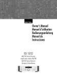
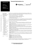
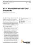
Examples of Harvard-based DSP architectures include the Texas Instruments
TMS320Cxx family of processors [6]: TMS320C1x, TMS320C2x and TMS320C2xx
– fixed-point 16-bit DSPs (see Figure 2-16) [45], and TMS320C4x – floating-point
32-bit DSP [46].
Figure 2-16. TMS320C26 DSP block diagram (source: [6])
26
Digital Signal Acquisition and Processing Systems
Mihai V. MICEA
Real-Time Data Acquisition and DSP Systems
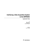
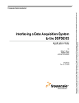
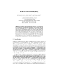
Examples of modified Harvard-based DSP architectures include the Motorola
DSP56k family of processors [5]: DSP568xx – fixed-point 16-bit DSPs [47] and
DSP563xx – fixed-point 24-bit DSPs [48, 49] (see Figure 2-17).
Figure 2-17. Motorola DSP56307 block diagram (source: [49])
Digital signal processing architectures feature additional logic to improve DSPspecific algorithm programming and execution. For example, the Motorola DSP56k
family of processors implements the following enhancements [5]:
y register and addressing support for various types of buffering (linear and
circular buffers) and table manipulation (e.g. step into tables at specified rates
for waveform generation);
y bit-reversed addressing scheme, useful for addressing the twiddle factors in
2k-point FFT addressing and to unscramble 2k-point FFT data;
y hardware support (registers and additional logic) for loop programming (i.e.
hardware DO loop instruction);
y most core registers can be programmed according to their specific functions
or can be used as general purpose registers;
y due to the highly parallel internal bus architecture, all the main units of the
DSP56k core can operate simultaneously and autonomously: PCU, Data
ALU, AGU, DMA Controller, Expansion Port, Clock Logic. The peripheral
interfaces of a particular DSP based on the '56k core can operate
autonomously as well.
Digital Signal Acquisition and Processing Systems
27
Real-Time Data Acquisition and DSP Systems
Mihai V. MICEA
The high efficiency of digital signal processors (high performance,
programming flexibility, reduced power consumption and low cost), along with the
corresponding software tools (assemblers, linkers, debuggers and compilers),
available to system and application programmers at moderate cost, recommend the
DSPs as the most elegant solution for current signal processing systems.
(4) Software on personal computers (PC)
DSP algorithms can be implemented as programs running on personal
computers. The solution has the advantage of maximum flexibility and portability as
the programming language used can be one of the common high-level languages
such as C or Java. Currently, the application programmer benefits from a very large
variety of software tools for DSP algorithm design and implementation on the PC:
assemblers for a wide range of target processors, linkers, debuggers, high-level
language compilers, emulators and simulators, as well as fully integrated software
development packages.
On the other hand, the relatively moderate-to-low execution speed that PCs
running under common operating platforms (e.g. MS Windows, Linux, etc.) are
capable of when executing specialized DSP applications does not recommend them
for use on autonomous, industrial systems. Also, common operating systems for PC
do not provide real-time operating capabilities, necessary for many signal processing
applications.
2.3 Common Architectures of DSAPS
Digital signal acquisition and processing systems are currently implemented in a
large variety of architectures, depending in most cases on the specifications and
requirements of a particular application (or set of applications). Thus, for high
performance signal processing applications, where flexibility and scalability are not
critical design issues but, instead, the system response time is important, compact
architectures of DSAPS are preferred.
On the other hand, moderate performance applications requiring greater
flexibility and scalability of the system use in most cases modular architectures of
DSAPS.
In the following paragraphs both types of architecture are discussed and some
exemplifications as case studies are presented.
2.3.1 Compact DSAPS
The architecture of a compact digital signal acquisition and processing system
incorporates all the necessary components discussed above in a single module:
y analog and digital interfaces to signals from the environment
y signal conditioning circuitry
y A/D and D/A conversion logic
28
Digital Signal Acquisition and Processing Systems
Mihai V. MICEA
Real-Time Data Acquisition and DSP Systems
y DSP hardware and software structures, having also the role of controlling the
proper operation of the entire system
y data communication interface with a host computer
A host computer can optionally be connected to the DSAPS to serve as
interactive user interface and as presentation and storage support for the results.
One of the most common examples of compact DSAP systems is the add-in data
acquisition card connected to an extension slot on the motherboard of a host PC. The
data acquisition card provides all the necessary circuitry for signal I/O, conditioning
and conversion. It is also equipped with the minimal logic required for control of the
on-board devices and their operation, and with the proper interface for data and
command exchange with the host computer as well. The PC plays the role of master
control device of the DSAPS operation, as well as the role of main digital processing
system, executing the DSP algorithms implemented by the application programmer.
It also serves as user interface.
"Aquarius-DSP 1" is such an example of compact DSAPS. It was developed by
the author during 1996-1998 within a research collaboration including DSPLabs
(Computer Software and Engineering Department) and D109 (Electrical Machines
Department) laboratories, and national research and development institutes such as
the Romanian Academy ("Academia Romana"), MEN ("Ministerul Educatiei
Nationale") and MCT ("Ministerul Cercetarii si Tehnologiei") [50 – 56].
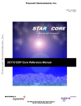
Figure 2-18. Aquarius-DSP 1 block diagram
The general architecture of the Aquarius-DSP 1 data acquisition card [12, 18,
32, 57] is specifically designed to reduce as much as possible the board control
circuitry and to simplify the power supply logic of the system. It is composed of the
following functional blocks (see Figure 2-18):
y A/D conversion block (ADCM), based on the Burr-Brown analog-to-digital
sampling converter ADS774 [25] and the MPC507 analog multiplexer [31]
Digital Signal Acquisition and Processing Systems
29
Real-Time Data Acquisition and DSP Systems
Mihai V. MICEA
y D/A conversion block (DACM), built around the Burr-Brown digital-toanalog converter DAC80 [58]
y Digital I/O block (IOM), implemented with the three-channel programmed
parallel interface 8255
y Command and control block of the DAQ card (DAQCDM)
y DAQ internal data/address/command bus (IBUS) which interconnects all the
on-board devices
y Communication interface of the DAQ card to a host computer (ICOMM),
using the ISA-AT standard bus architecture.
The DAQCDM block is basically composed of the device selection logic, clock
and synchronization circuitry (based on the 8254 programmable triple timer/counter
device) and the interrupt- and DMA- based data transfer logic. As a result, AquariusDSP 1 has a high operating autonomy.
Table 2-5 presents the general specifications and functional parameters of the
Aquarius-DSP 1 data acquisition card.
Table 2-5. General specifications of the Aquarius-DSP 1
Parameter
Type of DAQ
System
Interface with the
Host
Analog Inputs
Analog Outputs
30
Specifications
Data aquisition and conditioning add-in card
IBM PC-AT compatible
16-bit ISA-AT bus connector
Base I/O address is set with jumpers to:
0x100, 0x120 or 0x140
IRQ level is set within the command register to:
IRQ 5, IRQ 10, IRQ 11 or IRQ 12
DMA access channel is set within the command register to:
DMA 0 (8-bit transfer);
DMA 5, DMA 6 and DMA 7 (16-bit transfer, respectively)
Eight differential input channels
Input voltage ranges:
20 V: ±10 V – bipolar, 0 .. +20 V – unipolar;
10 V: ±5 V – bipolar, 0 .. +10 V – unipolar
Channel polling: consecutive cyclic, from a given channel
towards channel 0
Overvoltage protection: 70 Vp-p
Connector: 2x17 male header for flat ribbon cable
One differential output channel
Maximum output current: ±5 mA
Output voltage ranges:
5 V: ±2.5 V – bipolar, 0 .. +5 V – unipolar;
10 V: ±5 V – bipolar, 0 .. +10 V – unipolar;
20 V: ±10 V – bipolar
Digital Signal Acquisition and Processing Systems
Mihai V. MICEA
Digital I/O
A/D Conversion
D/A Conversion
Power Supplies
Dimensions
Real-Time Data Acquisition and DSP Systems
Output impedance: ±2.5 Ω, ±5 Ω, ±10 Ω, +5 Ω, +10 Ω,
depending on the selected voltage range
Connector: 2x5 male header for flat ribbon cable
Three 8-bit independent channels
Connector: three 2x5 male headers for flat ribbon cable
Conversion resolution: 12- or 8-bit, set through the
command register
Acquisition timing:
8.5 µs (max.), at a 12-bit resolution;
5.9 µs (max.), at an 8-bit resolution
Liniarity error: ±1 bit (LSB), max.
Conversion resolution: 12-bit
Conversion timing: 4 µs (max.)
Voltage: +5 V;
Current: 600 mA (max.)
Standard AT full size add-in card: 337x113 mm
Aquarius-DSP 1 has three main roles:
1.
Digital I/O. The operation can be performed through one of the three
independent 8-bit bidirectional data channels. Data transfer parameters are
programmed into the on-board 8255 device for each separate channel.
2.
D/A Conversion. Two steps are required to program the operation. First, the
DAQ board is set to the D/A acquisition mode. Next, data to be converted is
successively sent to the DAQ board in a 12-bit format.
3.
A/D Conversion. Three main issues concern the operation:
a) Analog input channel addressing
b) A/D acquisition modes
c) Fetch of the conversion results
a) The analog input channels are switched to the input of the ADS774 A/D
converter one at a time, through the MPC507 analog multiplexer. Channel
selection is controlled by a counter with a parallel preset input.
Channel selection can be performed using two addressing modes: lockedchannel mode (i.e. acquisition will be performed from a single input channel) or
channel-polling mode (i.e. cyclic polling of consecutive channels, from a given,
preprogrammed channel towards channel 0).
b) There are two distinct modes of A/D acquisition. A singular data
acquisition, controlled entirely by the user/application program on the host
computer represents the singular mode (or software mode). First, the DAQ card
is initialized by uploading the on-board Command Register with the proper
Digital Signal Acquisition and Processing Systems
31
Real-Time Data Acquisition and DSP Systems
Mihai V. MICEA
configuration word. Then, the acquisition operation is started using the software
driver provided with the board as interface. The results will be fetched from the
on-board Status Register after the conversion has been completed successfully.
Burst mode facilitates automatic sessions of a predefined (programmed)
number of data acquisition cycles. User/application programs need only to
program and initiate the operation and to store the results of each consecutive
conversion.
c) Conversion results can be fetched into the host computer in three ways.
The on-board Status Register can be manually read for the results of the last
successfully completed conversion cycle. The procedure is supported by the
software driver provided with the board and is usually used for singular
acquisition operations (singular mode).
Another, more efficient, method is based on interrupts. Aquarius-DSP 1 can
issue an interrupt to the host computer at the end of each conversion cycle. The
results are fetched into the PC while the next acquisition operation is
automatically started. If the application program allocates a memory buffer for
the acquisition results, it could perform other operations while the acquisition
process is executing on the DAQ board. When the buffer is filled by the
interrupt handler installed by the DAQ driver, the application can process the
entire set of results.
Aquarius-DSP 1 also provides the application programs with the mechanism
of collecting acquisition data through DMA. At the end of each conversion
process, the DAQ board issues a DMA request to the PC. While the DMA
controller of the host computer fetches the results into the memory, the next
acquisition cycle is automatically initiated.
The modules designed for evaluation of digital signal processors are another example
of compact DSAP systems. A common architecture of evaluation module (EVM)
consists of:
y Main digital signal processor
y EEPROM and RAM memory devices
y Interface logic for data and command exchange with the host computer
y Data acquisition (A/D and D/A conversion) logic (usually an audio CODEC)
y Non-intrusive test logic and test points (most boards use the JTAG bus
architecture – Joint Test Action Group)
y Clock and synchronization logic
y Test switches, push-buttons and LEDs
y Configuration jumpers and micro-switches
Figure 2-19 presents the functional block diagram of the evaluation module for
the Motorola DSP56303 digital signal processor [59, 60]. Exchange of data and
command between the EVM and the host computer is implemented through separate
interfaces. An RS232 serial link connected to the second on-board DSP (DSP56002)
provides support for command exchange and interpretation, for debug purposes.
DSP56002 has the main roles of controlling the serial communication with the host
computer and to interpret the specific command protocol of the debugger software
32
Digital Signal Acquisition and Processing Systems
Mihai V. MICEA
Real-Time Data Acquisition and DSP Systems
provided with the EVM package. Therefore, DSP56002 is also called "Command
Converter". The second interface with the host computer is the ISA bus connector,
enabling high-performance data exchange with the PC.
Figure 2-19. Motorola DSP56303EVM functional block diagram (source: [59])
The DSP-based evaluation modules are usually equipped with a voice or audio
codec (like the Crystal Semiconductor CS4125 [61] on the DSP56303EVM).
Therefore, such evaluation modules are moderate-performance compact DSAP
systems, able of acquiring and processing signals with a maximum bandwidth of
24 kHz (audio signals). Some practical examples and applications of digital signal
processing with the EVMs are described in the next section, to illustrate the power
and efficiency of EVMs as DSAP systems.
2.3.2 Modular DSAPS
Data acquisition and processing applications requiring high flexibility and scalability
use the modular approach. Thus, modular DSAPS are commonly used in industrial
environments, where inserting and removing of signal conditioning or signal
conversion modules is a relatively frequent operation, and where signal processing
and system control units are placed at a distance from the transducers, signal
conditioning and acquisition units.
Typically, the following components of a modular DSAPS can be implemented
as stand-alone units interconnected with various communication interfaces:
Digital Signal Acquisition and Processing Systems
33
Real-Time Data Acquisition and DSP Systems
y
y
y
y
y
Mihai V. MICEA
signal conditioning
A/D conversion
D/A conversion
digital I/O
signal processing and system control
Modular DSAP systems can be implemented in a large variety of configurations,
ranging from highly granular architectures (each component is a distinct module, see
Figure 2-20) to more compact configurations (for example, signal conditioning units
composing a module, distinct from the rest – see Figure 2-21).
Data/command link
Signal processing
and control unit
Backplane bus
A/D, D/A and Digital I/O
...
Signal
conditioning
modules
Transducers
(sensors/actuators)
Figure 2-20. Highly granular architecture of modular DSAPS
In the first case of DSAP architecture (Figure 2-20), each functional block is
implemented as an extension card: various signal conditioning boards for specific
types of transducers, A/D and D/A conversion cards (which can be of different types
and numbers, according to the application requirements), digital I/O boards, and
signal processing and system control boards.
The functional blocks are grouped into separate modules using special chassis
and racks with the main function of supporting the local communication between the
add-in cards, and the remote communication with the other module(s). Usually,
modules implement local and external communication as a backplane bus with
expansion slots for the add-in cards and a connector for the remote communication
cable/media.
In the latter case (Figure 2-21), modules feature the same structure and
configuration as described above, but the overall DSAP system contains less
modules. Figure 2-21 presents a DSAPS with two distinct modules: a data
acquisition, digital signal processing and control module (the PC computer with an
add-in DAQ card), and a signal conditioning module. The host computer resembles
34
Digital Signal Acquisition and Processing Systems
Mihai V. MICEA
Real-Time Data Acquisition and DSP Systems
the module chassis previously described, but the expansion slots of the
communication bus are placed on the system board (motherboard).
Signal processing and control unit
System bus
(Motherboard)
Add-in DAQ
board
Data/command link
Signal conditioning
module
Transducers
(sensors/actuators)
Figure 2-21. Two-module DSAPS
The National Instruments Corporation provides extensive solutions for modular
DSAP and instrumentation systems through the SCXI architecture [44].
Figure 2-22. Two SCXI system configurations (source: [62])
SCXI – Signal Conditioning eXtensions for Instrumentation, specifies the
terminal blocks, modules, chassis, cable assemblies, DAQ devices, protocols and
Digital Signal Acquisition and Processing Systems
35
Real-Time Data Acquisition and DSP Systems
Mihai V. MICEA
software that can be used to build various configurations of modular SDAP systems
and digital instrumentation networks (see Figure 2-22) [62].
Modular DSAP architectures provide high flexibility and scalability to the
applications requiring moderate processing speed.
One of their disadvantages is the strict compatibility required for the functional
cards to be inserted into a particular module chassis, as they must obey the exact
specifications of the expansion slots of the chassis backplane bus. On the other hand,
inter-module data/command exchange can be a strong feature of the system, when it
complies with commonly used communication standards (see Table 2-4).
36
Digital Signal Acquisition and Processing Systems
Mihai V. MICEA
Real-Time Data Acquisition and DSP Systems
3 Applications of Data Acquisition and DSP
This section approaches the vast number of applications of data acquisition and
digital signal processing, developed currently in almost every field of human activity.
First, a short overview of some of the main application domains of DSAP
systems is outlined.
Real-life examples of data acquisition and digital signal processing are further
presented. The applications were developed as research projects and grants at the
DSP Laboratories in Timisoara – DSPLabs, in collaboration with various partners
such as Motorola, Inc.
3.1 Application Domains of DSAP
Currently, DSAP systems support almost every human activity, as extremely
efficient, fast and precise command and control tools. From bank transactions and
modern digital telecommunication services to air and ground traffic control, or from
quick and easy office management to the advanced technology of satellites, digital
control systems can be found as key components.
Therefore, the application domains of digital signal acquisition and processing
are extremely numerous. Table 3-1 below synthesizes some of the application
domains of DSAP, classifying them into main fields of interest [5,6].
Table 3-1. Application domains of DSAP - a short overview
Application Domain
1. Generic signal processing
2. Graphics and image
processing
Applications of Data Acquisition and DSP
Example of Applications
Convolution
Correlation
Fast Fourier Transform (FFT)
Discrete Cosine Transform (DCT)
Windowing
Digital filtering
Adaptive filter desing and implementation
3-D image manipulation
Animation
Image filtering
Image enhancement
Digital maps
Image compression/transmission
Pattern/feature recognition
Robot vision
Movement tracking
37
Real-Time Data Acquisition and DSP Systems
3. Industrial/laboratory
instrumentation
4. Industrial equipment
5. Telecommunications
6. Medical equipment
7. Speech processing
38
Mihai V. MICEA
Waveform generation
Function generation
Transient analysis
High performance digital oscilloscopes
Spectrum analyzers
Computer aided/virtual instrumentation
Seismic processing
Robotics
Digital automation and control
Security access
Active noise cancellation
Engine and motor control
Vibration analysis
Tone generation
PCM CODECs
Medium-rate vocoders
VOIP (Voice Over IP)
MODEMs, FAXes
Line repeaters
Channel multiplexors
Echo cancellation
Digital communication interfaces
Mobile communications
Cordless telephones
ISDN equipment
Answering machines
Broad-band communication
Video-conference
Data compression/encryption
Multimedia communication systems
Advanced diagnoze
X-ray analysis
Electrocardiogram
Electroencephalogram
Nuclear Magnetic Resonance analysis
Hearing aid devices
Ultrasound equipment
Prosthetics
Chemical analysis equipment
Patient monitoring equipment
Speech synthesis
Speech recognition
Speech enhancement
Text-to-speech
Voice mail
Speaker authentication/verification
Applications of Data Acquisition and DSP
Mihai V. MICEA
8. Computers
9. Automotive Control
10. Consumer electronics and
entertainment
11. Military
Applications of Data Acquisition and DSP
Real-Time Data Acquisition and DSP Systems
Laser printers/copiers
OCR (Optical Character Recognition)
Signature recognition/authentication
Scanners and bar-code scanners
High-resolution monitors
Graphic accelerators/video processors
High-performance workstations
Engine control
System diagnosis
Adaptive ride control
Global positioning navigation
Anti-blocking system (ABS)
Vibration analysis
Active noise cancellation
Active suspension
Servo-steering
4-wheel steering
Airbag control
Voice commands
Intelligent display systems
Digital radio
Digital audio/TV
Music synthesizer
Multimedia
Educational/intelligent toys
UPS (Uninterruptible Power Source)
Digital cameras
Digital videodisk players
MP3 players
Low-noise, high-performance vacuum cleaners
and washing machines
Virtual reality
Karaoke
Arcade games
Special effects generation
Radar/Sonar processing
Fly-by-wire systems
Secure wireless communications
Radio frequency modems
Navigation
Missile guidance
Target detection, recognition and tracking
Night vision
Stealth systems
39
Real-Time Data Acquisition and DSP Systems
Mihai V. MICEA
3.2 DSP-Based Digital Oscilloscope
The first example of DSAP application is a digital oscilloscope implemented with a
DAQ board, a DSP-based evaluation module and a host computer as graphical user
interface. The application is part of DALT.1.2/2000 grant, developed at the DSPLabs
in collaboration with Motorola, Inc. [63].
Figure 3-1 presents the block diagram of the system, which is composed of [28]:
y A custom-made DAQ board for signal conditioning and acquisition
y DSP56303EVM evaluation module [59], which controls the overall system
operation and performs all the data processing required by the oscilloscope
y A host computer as graphical user interface providing an interactive system
control platform
Figure 3-1. General architecture of the system
Although the DSP56303EVM includes an on-board audio codec (the Crystal
Semiconductor CS4215 [61]), its performance is insufficient for a mediumperformance digital oscilloscope. Therefore, a simple data acquisition scheme was
designed, as presented in Figure 3-2.
Figure 3-2. Block diagram of the DAQ board
The Burr-Brown ADS774 was selected as the A/D converter device of the DAQ
system because of its simple interface and command requirements. Some of its main
40
Applications of Data Acquisition and DSP
Mihai V. MICEA
Real-Time Data Acquisition and DSP Systems
characteristics are synthesized in Table 3-2. The parameter values in bold type are
the ones selected for the DAQ system.
Table 3-2. ADS774 main parameters
Parameter
Operating principle
Specification
Successive approximation
with capacitor array
rCONV = 12 or 8
TCONV = 8 or 5.5
FS = 117 or 125
FSR = 20
–10 to +10
0 to +20
FSR = 10
–5 to +5
0 to +10
VREF = 2.5
Conversion resolution
Minimum conversion period
Maximum sampling rate
Full scale range
Bipolar input voltage
Unipolar input voltage
Full scale range
Bipolar input voltage
Unipolar input voltage
Internal reference voltage
Unit
–
bit
µs
kHz
V
V
Because the ADC is configured for 12-bit conversion resolution and 20-volt
FSR, the measuring precision of the system in terms of the LSB is:
LSB =
FSR
=
20
= 4.88 mV
212
2
The DAQ board is interfaced to the DSP-based evaluation module through a
special-purpose port of the DSP device - the Port A (see Figure 3-3).
rCONV
Figure 3-3. Interfacing the DAQ to the DSP system
The interface operates according to the general timing diagram presented in
Figure 3-4. The falling edge of the RD signal triggers a new conversion cycle on the
ADC and simultaneously loads the ACQ buffers with the previous conversion result.
The rising edge of RD strobes the buffered data to the DDB8–19 lines for storing into
a predefined data buffer in the DSP. After a TCONV delay, the result code of the
current conversion cycle is available at the data output lines of the ADC, ready to be
buffered. The full RD cycle period must be long enough to include the ADC
Applications of Data Acquisition and DSP
41
Real-Time Data Acquisition and DSP Systems
Mihai V. MICEA
conversion period (8 µs) plus a small delay to allow for the data transfer from the
buffer to the DSP. The period of the RD line is about 9 µs.
Figure 3-4. Interface timing diagram
Data acquisition is fully controlled by the DSP software. Additional userdefined routines can be easily integrated to process the acquired data when the buffer
is filled by the acquisition routine.
Figure 3-5 below presents the flowchart of the main program. The jagged arrows
in the figure represent asynchronous events, which imply wait states on the receiving
side. These events include:
y ECP data transactions between DSP and the host
y DSP timer interrupts which acknowledge sample acquisition operations
All data processing required by the oscilloscope is performed by corresponding
routines on the DSP, including the functions which a typical oscilloscope applies to a
periodic input signal:
y Signal synchronization (Syncro routine)
y Minimum and maximum amplitude (Min_max routine)
y Frequency and period (calculated interactively with the oscilloscope GUI)
y Fast Fourier Transform (fftr2a and bitrev macros)
A flexible and intuitive graphical user interface for the digital oscilloscope was
designed using a host computer. Data display windows, buttons, and slide bars
provide a control panel that is easy to use. To maximize throughput while
maintaining system flexibility, the ECP standard parallel interface is used to connect
the DSP to the host computer [27, 29].
The graphical user interface (see Figure 3-6) emulates the display and control
panel of an actual oscilloscope. It combines the features of an analog oscilloscope
with the advantages of digital processing:
y Continuous calculation of signal parameters (amplitude, frequency, period)
y Calculations performed either automatically or with the use of special,
interactive, mouse-controlled cursors
y Facilities for changing the oscilloscope time base and synchronization modes
y Memory capability
y Real-time FFT calculation and graphic display of the corresponding
frequency spectrum
42
Applications of Data Acquisition and DSP
Mihai V. MICEA
Real-Time Data Acquisition and DSP Systems
The GUI program was developed under the LINUX platform using the
"SVGALib" (Super VGA graphical library) in console mode.
Figure 3-5. Main program flowchart of the oscilloscope
Applications of Data Acquisition and DSP
43
Real-Time Data Acquisition and DSP Systems
Mihai V. MICEA
Figure 3-6. GUI of the oscilloscope
Table 3-3 summarizes the main functional parameters of the digital oscilloscope.
Table 3-3. Digital oscilloscope parameters
Parameter
Specification or Description
Analog signal interface
Input signal voltage range
–10 to +10 V / 0 to +20 V (10 Vpp input)
–5 to +5 V / 0 to +10 V (20 Vpp input)
Sampling rate
117 k samples per second (maximum)
Input signal frequency range
0 to 55.5 kHz
Input channels
1
Input impedance
12 kΩ (10 Vpp input)
50 kΩ (20 Vpp input)
Conversion resolution
12 bits
Least significant bit
2.44 mV (10 Vpp input)
4.88 mV (20 Vpp input)
Graphical user interface
General features
Real-time graphical display of acquired signal,
both for the time and frequency domains.
Basic signal parameter calculation in automatic
or manual modes.
Signal display modes
"RUN Mode" – real-time display
"FREEZE Mode" – static display of a captured
signal
44
Applications of Data Acquisition and DSP
Mihai V. MICEA
Variable time base
Synchronization modes
Amplitude calculation
Frequency/period calculation
Parameters calculated and
displayed continuously
Real-Time Data Acquisition and DSP Systems
256 stages, ranging from 588 to 123,460 µs per
division
Rising/falling edge;
Variable threshold in the –10 to +10 V range
"Automatic Mode": minimum and maximum
amplitude values, for every 512 samples of
acquired data.
"Manual Mode": two mouse-controlled
horizontal amplitude cursors.
Two vertical time cursors moved with the
mouse.
Oscilloscope calculates automatically the
corresponding time and frequency values.
Current time base (in µs/div);
Sampling frequency (in samples per second);
Synchronization threshold level (in V);
Instant values of the acquired signal,
corresponding to the two horizontal
amplitude cursors (in V);
Instant period and frequency values
corresponding to the two vertical cursors (in
seconds and Hz);
Signal frequency spectrum (FFT coefficients);
Instant frequency value corresponding to the
vertical cursor in the spectrogram (in Hz).
The application issued good results during testing and proved that the principles
used here could be extended to higher-performance DSAP systems by selecting a
faster DAQ module along with suitable software algorithms to accommodate larger
data throughput.
3.3 Real-Time Sonar Processing
SONAR (SOund NAvigation and Ranging) systems, like RADAR and electrooptical systems, have a large field of applications in robotics, navigation, and target
detection. The common principle of functioning is based on the propagation of waves
between a target and the detector. Sonars, however, differ fundamentally from radar
and electro-optics because the energy is transferred by acoustic waves.
Digital signal processing techniques increase the versatility of modern sonar
systems, resulting in a wider range of detection, better precision, data storage and
post-processing capabilities, as compared to previous, analog sonar systems. Digital
filtering algorithms can be applied to the received data, thus improving the target
detection capabilities in noisy environments. Therefore, using digital signal
processors (DSPs) to enhance sonar performance is advantageous.
Applications of Data Acquisition and DSP
45
Real-Time Data Acquisition and DSP Systems
Mihai V. MICEA
Real-time Sonar processing with digital signal processors is an application
developed at the DSPLabs in collaboration with Motorola, Inc., as part of the
DALT.1.3/2000 grant [64].
The basic sonar system estimates the distance to a target by calculating the
overall propagation time of a specially selected audio or ultrasound wave between
the sonar and the target. In an active sonar system the wave propagates from the
transmitter to the target and bounces back to the receiver analogous to pulse-echo
radar and passive sonar systems in which the target is the source of the energy that
propagates to the receiver.
In an active sonar system, the source of the acoustic wave is part of the sonar
system. The electrical energy from the transmitter must be converted into acoustic
energy, by a transducer. In a passive sonar system, the source is the target itself.
Knowing the propagation speed of the acoustic waves in the particular
environment where the sonar operates – say, in air – the estimated target distance
from the sonar is determined using (3 .1):
D = vs
δ
(3 .1)
2
m
where: v s = 340 is the propagation speed of acoustic waves in air,
s
δ [s] is the total propagation delay of acoustic waves.
The general system architecture of the real-time sonar system [65] is presented
in Figure 3-7.
Figure 3-7. Real-time Sonar system architecture
On the emitter-receiver platform is mounted a 400SR-400ST pair of capacitive
ultrasound transducers with the following characteristics: fSonar = 40 kHz, frequency
tolerance of ±1 kHz, good directivity and small size. On the same platform is
mounted the transducer interface logic: electronic amplifier and driver circuits and
the A/D conversion subsystem, based on the Burr-Brown sampling ADS-774 that
46
Applications of Data Acquisition and DSP
Mihai V. MICEA
Real-Time Data Acquisition and DSP Systems
works at a rate of 108 k samples per second for a 12-bit resolution. The emitterreceiver platform is rotated by a stepper motor.
A Motorola DSP56824EVM evaluation module [66, 67] was used as the core
unit of the Sonar system. It is directly connected to the emitter-receiver platform
through the DSP on-chip Port B, configured as GPIO port (General Purpose I/O).
The on-board DSP performs all the sonar-specific data processing operations,
including:
y Data communication with the transducer interface through the GPIO Port B
y Wave generation for the emitting ultrasound transducer
y Received echo analog-to-digital conversion
y Low-pass digital signal filtering
y Detection of the emitted pattern in the received data buffer
y Calculation of the target polar coordinates (distance and angle)
y Bidirectional data communication with the host computer through the serial
interface
y Stepper motor control and driving
When activated, the real-time sonar system performs the steps illustrated in the
general data flow below (Figure 3-8):
Figure 3-8. General Sonar operations flow
Applications of Data Acquisition and DSP
47
Real-Time Data Acquisition and DSP Systems
Mihai V. MICEA
Figure 3-8 emphasizes the most important routines developed for the Sonar
system, as well as their relative position in time during the operation of the Sonar.
One of the most important characteristics of the Sonar general data flow, evident in
the illustration, is the parallelism of routine execution between the host side and the
DSP side.
Items denoted in Figure 3-8 as "α" and "β" are stable states of the data flow.
When the execution on the DSP reaches the "α" state, it waits asynchronously for an
external event in order to go further – i.e., the host computer to signal it is ready to
receive results from the DSP. After receiving the signal, the DSP executes a series of
routines eventually reaching the distance calculation loop which corresponds to a 1.8
degree horizontal scan (two 0.9-degree rotation steps of the stepper motor) from a
total of 180 degrees – the sonar angular detection range.
In the same manner, when the execution on the host side reaches the "β" state,
the computer sends a "wait for data" command to the DSP and loops indefinitely
until one of the following conditions occur: DSP sends results through the serial link,
or the user stops the Sonar operation from the graphical user interface.
The Sonar DSP device generates a 40 kHz rectangular signal as the source
wave. After being amplified with the transducer interface logic and sent through the
emitting transducer, the resulting acoustic wave becomes a sinusoid. The source
signal is generated over 40 periods to ensure enough signal energy for range
maximization.
At the reception side, the DSP commands the A/D conversion block for 2048
consecutive acquisition cycles of the received echo. The resulting echo samples are
stored in a 2 K-word data buffer on the DSP on-chip memory for further processing.
First, the received echo is filtered with a simple digital low-pass moving average
filter with 20 coefficients. Next, the maximum value and its index in the received
data buffer are calculated. The Sonar program will interpret this information to
extract the target distance in millimeters. To avoid the appearance of "fake" targets
when the Sonar receives only noise (i.e. no real target exists on current transducer
direction, in the detection range), the resulted maximum value is compared to a
predefined threshold. If the maximum is higher than the threshold, the Sonar stores it
as the distance to the target.
The angle of the target is the second polar coordinate calculated by the Sonar.
Actually, it results from the current angular position of the transducer platform. Two
rotation parameters, rightcount and leftcount, are altered by the stepper motor
control routine. For example, if the transducer platform is currently turning leftward,
leftcount contains the number of rotation steps to be done until the complete
rotation to the left will be performed (totaling 180 degrees), while rightcount
variable is forced to "0".
The transducer platform is consecutively rotated with 1.8-degree steps from left
to right and vice versa, totaling an angular range of 180 degrees for the Sonar system.
At the end of a detection cycle (i.e. the Sonar search procedure for a rotation step, see
Figure 3-8), the DSP sends to the host computer the target coordinates (distance, in
mm, and angle, in degrees) through the serial data link.
The host computer (see Figure 3-7) performs within the Sonar system two basic
tasks:
48
Applications of Data Acquisition and DSP
Mihai V. MICEA
Real-Time Data Acquisition and DSP Systems
y establishes a serial data link with the DSP for command and result
transactions, and
y provides an intuitive and interactive graphical user interface for the Sonar.
Command and data communication with the DSP is implemented on the host
side through the PC standard serial interface (RS232), configured at its maximum bit
rate: 115.2 kbps, with 8 data bits, one stop bit and no parity ("8N1"). The selected bit
rate is high enough for the proper sonar functioning in real-time, because the
necessary data throughput between the host computer and DSP requires medium
rates.
The sonar GUI was designed to run under Windows 9x/NT platforms on a
recommended graphical resolution of 800 × 600 pixels. Users control the general
sonar behavior – "start", "stop", and "exit" – using the corresponding buttons
provided by the interface (see Figure 3-9).
Figure 3-9. Sonar graphical user interface
Sonar operation and detection results are displayed in real-time using three
modes:
1. Graphical display window – depicts the detected targets at relative
coordinates corresponding to their real position to the Sonar transducers.
This is the most intuitive mode, similar to classical Radar and Sonar scopes.
2. Numerical mode – displays the exact polar coordinates of the currently
displayed target in two separate boxes: one for the target range (in
millimeters) and the other for the angular position (in degrees).
3. Progress bar display – presents the distance to the currently displayed target
in an intuitive manner by showing a scale of the Sonar minimum and
maximum detection range.
Applications of Data Acquisition and DSP
49
Real-Time Data Acquisition and DSP Systems
Mihai V. MICEA
The real-time Sonar system was successfully implemented and tested using
targets of different sizes, shapes, and surfaces. Theoretical performance
characteristics are based on two main parameters.
First, the maximum sonar detection range is a parameter of sound velocity
(application-independent variable), of the data buffer length and echo sampling rate,
the last two being the application-dependent variables:
L
v
Dmax = buffer ⋅ s
2
FS
(3 .2)
where: Lbuffer = 2048 words – is the length of the received data buffer;
FS = 108 kHz – is the sampling rate used for echo acquisition;
vs = 340 m/sec – is the velocity of the acoustic waves in the air at normal
temperature.
The resulting theoretical value for the maximum detection range of the Sonar
system is:
(3 .3)
Dmax = 3223.7 mm
The value in (3 .3), resulting from (3 .2), is a theoretical one, because the energy
loss of acoustic waves during propagation in the air was ignored, and also because of
the reflection loss on the target. These parameters are dependent on local air pressure
and temperature, as well as the size, surface, and shape of a particular target. The
acoustic noise present in the environment as well as the induced electrical noise at
the reception side was also ignored.
The practical results obtained demonstrate the importance of the parameters
ignored in the equations above. At the maximum theoretical limit of the distance
(about 3.2 m) and using a large surface (1000 × 500 mm rectangle) the system was
able to detect the target, but the results were highly unstable (at the limit of error
threshold).
The second main sonar parameter is the so-called detection resolution – the
uncertainty of distance calculation. For the proposed sonar implementation, the
detection resolution is given by:
ε=
vs
= 3.148 mm
FS
(3 .4)
Again, practical evaluations of the parameter in (3 .4) issued higher results, for
the same reasons as explained above.
3.4 Real-Time Person Tracking Video System
A simple and efficient solution to the real-time automatic person tracking problem is
proposed by the application funded by Motorola, Inc., under grant DALT.2.5/2001,
at the Digital Signal Processing Laboratories in Timisoara – DSPLabs.
The application objective is a video camera-based system with the ability to
follow moving objects appearing in the sequence of images acquired in real-time.
Figure 3-10 depicts the general architecture of the real-time person tracking video
system that was implemented for testing purposes.
50
Applications of Data Acquisition and DSP
Mihai V. MICEA
Real-Time Data Acquisition and DSP Systems
Video camera
Video
link
Rotating
platform
Host
computer
Stepper motor
Data and
control link
Motor
control link
DSP module
Figure 3-10. General architecture of the person tracking system
Due to the high processing power and data throughput required by the
application, the real-time tracking algorithm was implemented entirely on a PC,
which also controls the acquisition of the video stream from the camera. After
detecting the movement and computing its characteristics, the main algorithm sends
proper data and control words to a DSP-based module.
The primary role of the DSP module within the test system is to process data
coming from the host computer and to command accordingly the stepper motor that
drives the rotating platform. The video camera, which is mounted on the rotating
platform, is thus continuously oriented towards the moving object (person), in realtime.
The target system for the application is the DSP-based module, which will run
all the necessary image processing and person tracking algorithms, as well as the
control routines for the video stream acquisition and for driving the rotating platform.
This will provide a real-time person tracking system with a very good
cost/performance ratio.
In this case, the PC station will simply be a passive component of the system,
used mainly to display the tracked person (see Figure 3-11).
Because the main goal is to follow a moving person, in the case of more than
one moving object, the application implements the heuristic principle of following
the largest moving object (i.e. the object that produces the largest surface, as a result
of motion thresholding and segmentation of the video frames). Thus, even if two
objects have the same visible surface, if one object is moving faster, then it has a
larger movement surface.
The tracking algorithm developed and implemented here relies on motion
segmentation techniques. More precisely, these techniques use threshold methods for
detecting the changes that appear between two consecutive frames from the image
sequence. Thus, motion segmentation represents the labeling of each and every pixel
that is associated with an independently moving object from a sequence of frames.
As in any segmentation process, the use of an adaptive threshold algorithm facilitates
the success.
Applications of Data Acquisition and DSP
51
Real-Time Data Acquisition and DSP Systems
Mihai V. MICEA
Video camera
Video
link
Host
computer
Rotating
platform
Stepper motor
Motor
control link
DSP module
Figure 3-11. Real-time person tracking system controlled with a DSP
Motion segmentation is performed by frame differentiation due to the simplicity,
speed and relatively moderate processing requirements of this technique. Every two
consecutive image frames are differentiated and the result is compared with a
predefined threshold, as in (3 .5):
1 if ∆ n,n−1 ( x, y ) > P
Ψn,n−1 ( x, y ) =
0 otherwise
(3 .5)
where: Ψn,n–1(x,y) is the image segmentation function,
n and n–1 are the indices of two consecutive image frames,
x and y are the Cartesian coordinates of each pixel in a frame, and
∆n,n–1(x,y) is the frame difference function, defined as in (3 .6).
∆ n,n−1 ( x, y ) = Fn ( x, y ) − Fn−1 ( x, y )
(3 .6)
The function described in (3 .6) calculates the difference between two
consecutive frames, Fn(x, y) and Fn–1(x, y), on a per-pixel basis. Assuming that
brightness and contrast between any two consecutive frames remain the same (in
practice this is usually not true), the places where (3 .7) is verified indicate
“changed” regions.
∆ n,n−1 ( x, y ) ≠ 0
(3 .7)
Because of the observation noise, (3 .7) becomes true very rarely, so the
“changed” regions will not always indicate the moving objects from the frames with
reasonable accuracy. Therefore, a threshold P must be applied, as in (3 .5). As a
result, the "changed" regions will correspond to:
Ψn,n−1 ( x, y ) = 1
Figure 3-12 illustrates the concept of the segmentation algorithm described by
the equations above and used by the tracking application.
The image resulted from segmentation is further partitioned into Nb vertical
strips, of equal width, L.
52
Applications of Data Acquisition and DSP
Mihai V. MICEA
Real-Time Data Acquisition and DSP Systems
Fn−1(x, y)
Ψ n, n−1(x, y)
Fn (x, y)
Figure 3-12. Basic concept of the segmentation algorithm
For each vertical strip (i.e. for b from 0 to Nb – 1), the algorithm computes:
Sb =
L −1 H −1
∑ ∑ Ψ n,n−1(b × L + j, k )
(3 .8)
j −0 k =0
where: H is the height of the strips (actually, the height of the image frames).
With the Sb values, the maximum is then calculated, as in (3 .9). The bMAX
indicates the strip corresponding to the most important movement in the segmented
image, but it also gives the number of steps and the direction for the stepper motor,
to drive the video camera. The total number of strips (and, the width of each
individual strip as well) must be closely related with the characteristics of the
electrical motor.
bMAX = max(S b )
b = 0 .. N b −1
(3 .9)
At the same time, bMAX will be used to classify all the strips into moving strips
and still strips: if the Sb value of strip b in the segmented image is at least 40% of
bMAX, then it will be classified as a moving strip; otherwise, it will be classified as a
still strip:
40
moving if Sb ≥
bMAX
b is
100
still
otherwise
(3 .10)
Figure 3-13. Strip classification in the segmented image
Applications of Data Acquisition and DSP
53
Real-Time Data Acquisition and DSP Systems
Mihai V. MICEA
Figure 3-13 exemplifies the procedure of classifying the vertical strips into
moving strips (depicted with dark color) and still strips (white). As a result, the
motion segmentation is eventually characterized by two more values, bMINn and
bMAXn, in addition to bMAX. The two new values represent the leftmost moving strip
and the rightmost moving strip, respectively, from the segmented image.
The operation of the motion segmentation algorithm in a real situation is
exemplified in Figure 3-14. On the left side of the picture there is a graphical
representation of bMINn, bMAXn and bCn for Ψn,n–1(x, y) (corresponding to Fn(x, y) and
Fn–1(x, y) frame processing), related to the Sb values of every strip. In the case of the
tracking system, the width of the vertical strips can be of 2 ÷ 8 pixels. In the middle
of the picture is the representation of the corresponding difference image, after the
motion segmentation Ψn,n–1(x, y) is applied.
The parameter bCn represents the center of the moving object to be followed by
the tracking system. It is calculated with (3 .11).
bCn = bMAXn – bMINn
(3 .11)
Figure 3-14. A real-life example of the motion segmentation algorithm
Direction and speed estimation of the moving object is the main goal of the
tracking algorithm. The estimation is based simply on storing the bCn parameters for
each two consecutive processing steps k–1 and k, and calculating their signed
difference (3 .12).
vk, k–1 = bCk – bCk–1
(3 .12)
54
Applications of Data Acquisition and DSP
Mihai V. MICEA
Real-Time Data Acquisition and DSP Systems
The magnitude of vk, k –1 quantifies the movement of the tracked object, while its
sign represents the movement direction. With these two basic parameters the person
tracking algorithm can control the rotating platform to orient the video camera
towards the moving object.
Testing the person tracking system by using the corresponding implementation
(Figure 3-10) proved that all the project objectives set in the specification phase were
successfully met. Some of the performance parameters featured by the person
tracking system are listed below:
y The maximum distance for a good tracking of human motion is 15 m
y The minimum distance for tracking and following human motion is 0.5 m
y The maximum speed for a moving human-shaped object to be tracked and
followed was evaluated at 7 m/sec (when the object is moving on a trajectory
at a distance of 5 m away from the video camera)
y There is no minimum speed for tracking and following a person that moves at
a typical distance of 5 meters from the video camera
y Using a stepper motor with 0.9° per step and a torque of 64 steps per second,
we can consider that, ideally, a person moving with a speed of 7.87 m/sec at
5 m away from the video camera can still be tracked.
Applications of Data Acquisition and DSP
55
Mihai V. MICEA
Real-Time Data Acquisition and DSP Systems
4 High Performance Multiprocessor DSP Architectures
High performance digital signal processing platforms are currently the most efficient
solutions for embedded and real-time applications involving signal acquisition and
processing at high rates.
A continuously increasing number of applications require digital control devices
with tremendous processing power and data throughput, on one hand, and reduced
consumption power and small physical sizes, on the other hand. Moreover, the digital
data processing and control systems must operate under tight real-time specifications
and, in most cases, are the main platform of embedded systems. The most common
types of such applications include:
y Multimedia systems (multi-channel audio/voice coding and compression,
audio-conferencing, image and video stream compression and transmission,
three-dimensional graphics and animation, video-conferencing, advanced
human-machine interfaces, speech processing, security systems, virtual
reality, etc.);
y High-performance communication systems (2G, 2.5G and 3G mobile
telecommunication systems, wireless infrastructure (basestation processing,
transcoder units, digital circuit/packet switching centers), packet telephony
(voice, fax and data processing), network nodes and gateways, broadband
communication, etc.);
y Intelligent/autonomous machines (intelligent robots operating in hazardous or
unreachable environments, marine, aeronautic and space navigation and
exploration equipment, satellites, etc.).
This section provides an overview of one of the most representative high
performance digital signal processing platforms: the Motorola StarCore-based
processors.
4.1 Motorola StarCore SC140 DSP Core
4.1.1 General Description
The Motorola StarCore SC140 digital signal processing (DSP) core [68] implements
an innovative architecture that addresses high-performance DSP applications such as
wireline and wireless communications, multimedia systems and computationalintensive digital control.
The SC140 is a flexible programmable DSP core that provides exceptional
performance, low power consumption, efficient compilability and compact code
density. It implements a variable-length execution set (VLES) execution model,
High Performance Multiprocessor DSP Architectures
57
Real-Time Data Acquisition and DSP Systems
Mihai V. MICEA
enabling maximum parallelism by allowing multiple address generation and data
arithmetic and logic units to execute multiple instructions in a single clock cycle.
Key features of the SC140 core include the following:
y Up to 4 MMACS (million multiply-and-accumulate) operations per second
and 10 RISC MIPS (million RISC instruction words per second) for each
megahertz of clock frequency
y Four arithmetic and logic units (ALU), each comprising:
à A true (16 × 16) + 40 → 40-bit multiply-and-accumulate (MAC) unit
à A bit field unit, composed of a true 40-bit parallel barrel shifter, a mask
generation unit and a logic unit
y Hardware support for fractional and integer data types
y Sixteen 40-bit data registers for fractional and integer data operand storage
y An address generation unit (AGU), composed of two 32-bit address
arithmetic units (AAU) and a bit mask unit (BMU) for easily setting,
clearing, inverting or testing a selected group of bits in a register or memory
location
y Sixteen 32-bit address registers, four address offset registers and four modulo
address registers
y Unified data/program memory addressing space
y Zero-overhead hardware loops with up to four levels of nesting
y Real-time debug capabilities through the enhanced on-chip emulation
(EOnCE) module
y Low power wait standby mode
4.1.2 Core Architecture
Figure 4-1 presents the block diagram of the SC140 core. It provides the following
main functional units:
y Data arithmetic and logic unit (DALU)
y Address generation unit (AGU)
y Program sequencer unit (PSEQ)
Although SC140 uses a unified data/program addressing space, its internal
architecture (functional units, buses and register files) is designed to comply with the
modified Harvard architecture. Thus, the following buses are implemented:
y Two data memory buses (address and data pairs: XABA and XDBA, and
XABB and XDBB, respectively)
y A program address and data pair (PAB and PDB)
y Special buses to support external instruction set accelerator units
The data arithmetic and logic unit (DALU) contains a register file of sixteen 40bit registers, four parallel ALUs (each containing a multiply-and-accumulate unit –
MAC – and a bit field unit – BFU – with a 40-bit barrel shifter) and eight data bus
shifters/limiters (see Figure 4-2).
58
High Performance Multiprocessor DSP Architectures
Mihai V. MICEA
Real-Time Data Acquisition and DSP Systems
Figure 4-1. Block diagram of the SC140 core (source: [68])
XDBA
XDBB
64
64
8
2
1 Shifter/Limiter
40
40
..
. . . 40
40
39
.
64
64
(8 buses)
32 31
16 15
0
L0
D0.e
D0.h
D0.l
D0
L1
D1.e
D1.h
D1.l
D1
L2
D2.e
D2.h
D2.l
D2
L15
D15.e
D15.h
D15.l
D15
DALU Register File
40
40
40
ALU
1
(4 x 3 buses)
...
2
3
4
Figure 4-2. DALU architecture
High Performance Multiprocessor DSP Architectures
59
Real-Time Data Acquisition and DSP Systems
Mihai V. MICEA
All the BFU and ALU units can access all the sixteen DALU registers
(D[0..15]), as source operands, destination operands, accumulators, or as general
purpose registers.
Each register is partitioned into three portions (see Figure 4-2): two 16-bit
registers (D[0..15].l and D[0..15].h) and one 8-bit register (extension portion,
D[0..15].e). In addition, one limit tag bit is associated with each data register
(L[0..15]). Accesses to/from these registers can be in widths of 8 bits, 16 bits, 32 bits,
or 40 bits, depending on the instruction.
The two 64-bit wide data buses (XDBA and XDBB) between the DALU register
file and the memory enable a very high data transfer speed (by allowing two data
moves in parallel, each up to 64 bits in width), as well as a very flexible data
manipulation mechanism (through the move instructions that allow variable data
widths – see Table 4-1).
Table 4-1. Types of move instructions with respect to data width
Move instruction
MOVE.W
MOVE.F
Description
Load or store bytes (8-bit)
Load or store integer or fractional words
(16-bit)
MOVE.2W
MOVE.2F
MOVE.L
Load or store two integers, two fractions
and long words, respectively (32-bit)
MOVE.4W
MOVE.4F
Load or store four integers and four
fractions, respectively (64-bit)
Load or store two long words (64-bit)
MOVE.B
MOVE.2L
DALU supports three types of two's complement data formats: signed fractional
(SF), signed integer (SI) and unsigned integer (UI). With the signed fractional
format, the N-bit operand is represented using the "1.[N–1]" bit format (1 sign bit, N–
1 fractional bits). The resulting range for signed fractional numbers is:
–1.0 ≤ SF ≤ +1.0 – 2 –(N – 1)
Using the signed integer (SI) format, the N-bit operand is represented as N
integer bits. The range for signed integer numbers is:
–2 N – 1 ≤ SI ≤ 2 N – 1 – 1
Unsigned integer numbers can be thought of as positive only and lie in the
following range:
0 ≤ UI ≤ 2 N – 1
For example, the most negative number that can be represented for long-word
signed fractions is –1.0 (of which the internal representation is $8000 000), while
the most positive fractional long word is 1.0 – 2–31 (corresponding to $7FFF FFFF).
The address generation unit (AGU) is one of the execution units of the SC140
core and performs effective address calculations using the necessary integer
arithmetic. A block diagram of the AGU is depicted in Figure 4-3, emphasizing its
main units and registers.
60
High Performance Multiprocessor DSP Architectures
Mihai V. MICEA
Real-Time Data Acquisition and DSP Systems
Figure 4-3. AGU block diagram (source: [68])
All of the AGU registers are 32-bit wide, and can be used according to their
specific purpose, or as general-purpose storage (except for the MCTL, NSP and ESP
registers). The sixteen address registers R[0..15] can contain addresses or generalpurpose data. They are composed of two separate banks: a low bank (R[0..7]), and a
high bank (R[8..15]) which can be used either as address registers or as base address
registers (B[8..15]) for the modulo addressing mode. The modifier registers (M[0..3])
can be used in the modulo addressing mode and they contain the value of the
modulus modifier. The offset registers (N[0..3]) can contain offset values used to
increment/decrement address registers in address register update calculations.
The SC140 core has two 32-bit stack pointer registers used implicitly in all PUSH
and POP instructions: the normal stack pointer (NSP) and the exception stack pointer
(ESP). Only one stack pointer is active at one time: NSP for the Normal mode and
ESP for the Exception mode. Thus, SC140 provides a simple and efficient
mechanism for multitasking and operating system implementation. The NSP is used
by tasks when the core is in the normal mode of processing, while the ESP is used in
the exception mode by the OS and interrupts (see Figure 4-4).
DALU also contains two identical address arithmetic units (AAU), each
composed of a 32-bit full adder (called an "offset adder"), which can perform the
following operations:
y Add or subtract two AGU registers
y Add an immediate value
y Increment or decrement an AGU register
High Performance Multiprocessor DSP Architectures
61
Real-Time Data Acquisition and DSP Systems
Mihai V. MICEA
y Add the PC value
y Add with reverse-carry
Memory
space
Memory
space
NSP
Task
Stack
Space
for
Intr.
Task i
ESP
NSP
Task
Stack
Exception
Stack
Space
for
OS
Calls
OS
Task i+1
Figure 4-4. SC140 stack support for multitasking
The bit mask unit (BMU) is used to perform bit mask operations such as setting,
clearing, changing or testing bits in a destination according to an immediate mask
operand. All bit mask instructions are typically executed in two cycles and work on
16-bit data, which can be a memory location or a portion (high or low) of a register.
Table 4-2 summarizes the addressing modes of the SC140 core. The addressing
modes are related to where the operands are to be found and how the address
calculations are to be made.
Table 4-2. SC140 addressing modes summary
Category
Addressing Mode
Register Direct
Data, address or control register
Address
No update
Register Indirect Post-increment
Post-decrement
Post-increment by offset Ni
Indexed by offset N0
Indexed by address register Rm
Short displacement
Word displacement
62
Assembler Synthax
Dn [Dm Di Dj]
(Rn)
(Rn)+
(Rn)(Rn) + Ni
(Rn + N0)
(Rn + Rm)
(Rn + x)
(Rn + xxxx)
High Performance Multiprocessor DSP Architectures
Mihai V. MICEA
Real-Time Data Acquisition and DSP Systems
PC Relative
PC Relative with displacement
Special
Immediate short data
Immediate word data
Immediate long data
#xx (5, 6 or 7 bits)
#xxxx (16 bits)
#xxxxxxxx (32 bits)
Absolute word address
Absolute long address
Absolute jump address
Implicit reference
xxxx (16 bits)
xxxxxxxx (32 bits)
Address
Modifier
(defined by the
MCTL register)
xxxxxxxx (32 bits)
Software Stack Reference in
data memory (using NSP
or ESP);
Program Control Unit
Register Reference;
Program Memory Reference
AM[0..3] ← 0000
Linear addressing
in the MCTL register
Reverse-carry addressing 1
Modulo addressing
#xx (8 bits)
#xxx (10 bits)
#xxxx (16 bits)
#xxxxx (20 bits)
2
Multiple wrap-around modulo
addressing 3
AM[0..3] ← 0001
in the MCTL register
AM[0..3] ← 10xx
in the MCTL register
AM[0..3] ← 11xx
in the MCTL register
Notes:
Reverse-carry addressing is useful for 2k point FFT (Fast Fourier
Transform) addressing (addressing the twiddle factors, or unscrambling FFT
input/output data). This mode uses address registers R[0..7] and the offset
registers N[0..3], and is performed in the hardware by propagating the carry
from each pair of added bits in the reverse direction (from the MSB toward the
LSB end).
1
2
Modulo address modification is useful for creating circular buffers for FIFO
queues, delay lines, and sample buffers up to 231 words long. This mode uses the
base address registers B[0..7] as pointers to the start of the circular buffer,
address registers R[0..7] as pointers to data words inside the buffer, and modifier
registers M[0..3] for defining the size of the circular buffer.
Each base address register (Bn register) is associated with an Rn register
(B0 with R0, and so on). Each register Rn has one Mj register assigned to it by
encoding in the MCTL. The lower boundary value of the buffer resides in the
Bn register, and the upper boundary is calculated as Bn + Mj – 1 (see Figure
4-5).
High Performance Multiprocessor DSP Architectures
63
Real-Time Data Acquisition and DSP Systems
Mihai V. MICEA
Memory
space
MCTL
Mj
Modulo type
Modulo
mod
Rn
Pointer
Bn
Base addr.
Upper
boundary:
Bn + Mj − 1
Circular
Buffer of
Mj
locations
Base address:
Bn
Figure 4-5. Modulo addressing procedure
3
Multiple wrap-around addressing is useful for decimation, interpolation and
waveform generation. In multiple wrap-around modulo addressing mode, the
modulus M is a power of 2 in the range of 21 to 231. The value M–1 is stored in
the modifier register (Mj). The B[0..7] registers are not used for multiple wraparound modulo addressing; therefore, their corresponding R[8..15] registers can
be used for linear addressing.
The lower and upper boundaries are derived from the contents of Mj. The
lower boundary (base address) value has zeros in the k LSBs where M = 2k and
therefore must be a multiple of M. The Rn register involved in the memory
access, is used to set the MSBs of the base address. The base address is set so
that the initial value in the Rn register is within the lower and upper boundaries.
The upper boundary is the lower boundary plus the modulo size minus one (base
address + M – 1).
The program sequencer unit (PSEQ) performs instruction fetch, instruction
dispatch, hardware loop control, and exception processing. PSEQ controls the
different processing states of the SC140 core, and consists of three hardware blocks:
y Program dispatch unit (PDU) – responsible for detecting the execution set out
of a one or two fetch set, and dispatching the various instructions of the
execution set to their appropriate execution units where they are decoded.
y Program control unit (PCU) – responsible for controlling the sequence of the
program flow.
y Program address generator (PAG) – responsible for generating the program
counter (PC) for instruction fetch operations, including hardware looping.
PSEQ contains the following special-purpose 32-bit registers:
y PC – Program counter register
y SR – Status register
y SA[0..3] – Four loop start address registers
64
High Performance Multiprocessor DSP Architectures
Mihai V. MICEA
Real-Time Data Acquisition and DSP Systems
y LC[0..3] – Four loop counter registers
y EMR – Exception and mode register
y VBA – Interrupt vector base address register
To support parallel execution, the SC140 core uses a variable length execution
set (VLES) architecture with a static grouping mechanism. Several instructions can
be grouped together to form an execution set, which is dispatched to the execution
units in parallel. The core contains six independent execution units: four ALUs and
two AAUs. An execution set can contain up to six instructions with a maximum of
eight words. For many instructions, an execution set takes only one clock cycle.
Further parallelization is provided by the SC140 through a five-stage execution
pipeline (see Figure 4-6).
Prefetch
PSEQ
Fetch
Dispatch
AGU
DALU
• Generate addresses for program fetch
• Update fetch counter (FC)
• Read fetch set from memory
• Dispatch instructions
• Decode AGU instructions
Address
Generation
•
•
•
•
•
Decode DALU instructions
Generate addresses for data load and store operations
Perform address calculations: normal and change-of-flow
Perform AGU arithmetic instructions
Update AGU registers
Address
Generation
•
•
•
•
•
Decode DALU instructions
Generate addresses for data load and store operations
Perform address calculations: normal and change-of-flow
Perform AGU arithmetic instructions
Update AGU registers
Figure 4-6. Instruction pipeline stages on the SC140
4.1.3 SC140 Programming
To exemplify the SC140 core programming, a simple matrix multiplication was
chosen. The algorithm calculates the product of two square matrixes, A and B, each
of size four rows by four columns, as in (4 .1).
This particular matrix size was chosen for the main reason that the SC140
features four independent ALUs, thus maximizing concurrent processing of the
necessary operations when in multiple of four.
High Performance Multiprocessor DSP Architectures
65
Real-Time Data Acquisition and DSP Systems
A
4×4
a1,1
a
= 2,1
a3,1
a 4,1
A× B = C
4×4
a1, 2
a 2, 2
a3, 2
a 4, 2
Mihai V. MICEA
a1, 4
a 2, 4
; B
a3, 4
a 4, 4
a1,3
a 2 ,3
a3,3
a 4 ,3
c1,1
c
= 2,1
c3,1
c 4,1
c1,2
c 2, 2
c3, 2
c 4, 2
c1,3
c 2, 3
c3,3
c 4, 3
4×4
b1,1
b
= 2,1
b3,1
b4,1
b1, 2
b2, 2
b3,2
b4, 2
b1,3
b2,3
b3,3
b4,3
b1,4
b2,4
b3, 4
b4,4
c1, 4
c 2, 4
c3, 4
c 4, 4
(4 .1)
where:
4
ci , j = ∑ ai ,k ⋅ bk , j
(4 .2)
k =1
In pseudo-code, the matrix multiplication kernel can be written as in the
following Code Listing 4-1:
Code Listing 4-1. Classical matrix multiplication pseudo-code
for i = 1 to 4 do
for j = 1 to 4 do
{
c[i,j] = 0;
for k = 1 to 4 do
c[i,j] = c[i,j] + a[i,k]*b[k,j];
}
The proposed algorithm emphasizes some of the programming facilities
provided by the SC140 core architecture, like:
y extensive use of the general-purpose DALU registers for multiple operand
manipulation;
y use of highly parallel instruction set;
y modulo addressing for circular buffer programming;
y use of nested hardware loops.
Figure 4-7 presents the memory layout used to store the matrix data for
maximum efficiency of the algorithm operation. Matrix A and C are stored in natural
order (row-wise), while matrix B is stored column-wise. Address register R0 is used
to address in the linear mode each row of matrix A, starting from a_base. Data
registers D[0..3] are used to store all the four elements of a row in a single instruction
cycle. R0 will be incremented with 4 for every loop (using offset register N0), to
address the next row of matrix A.
Matrix B is accessed using the (B1, R1, M1) address register set, in the modulo
mode. R1 is also incremented with 4 for every loop (using offset register N1), to
address the next column of matrix B. When R1 reaches the highest address in the
circular buffer (i.e. b4,4), which is specified by the M1 register, it will be
automatically decremented point back to the base of the buffer (i.e. b4,4, specified by
the value b_base in B1 register).
66
High Performance Multiprocessor DSP Architectures
Mihai V. MICEA
Real-Time Data Acquisition and DSP Systems
The results of multiplication of each row and column between the two matrixes
are stored in the memory space defined for matrix C (starting from c_base), using
data register D14 and address register R2 in linear addressing mode.
Memory layout
for matrix A
Memory layout
for matrix B
a 4,4
b 4,4
R0
a_base
...
c 4,1
c 3,4
b 1,3
b 4,2
c 3,1
c 2,4
D3
N1
D2
D1
D0
R1
B1
b_base
b 1,2
b 4,1
b 3,1
b 2,1
b 1,1
...
a 2,1
a 1,4
a 1,3
a 1,2
a 1,1
D7
D6
D5
D4
R2
c_base
...
a 3,1
a 2,4
...
...
b 1,4
b 4,3
...
a 4,1
a 3,4
...
...
c 4,4
...
M1
...
N0
Memory layout
for matrix C
c 2,1
c 1,4
c 1,3
c 1,2
c 1,1
D14
Figure 4-7. Memory layout for matrix multiplication
The basic implementation of the 4×4 matrix multiplication algorithm on the
SC140 core is presented in Code Listing 4-2.
Code Listing 4-2. Matrix multiplication algorithm for the SC140
; Algorithm initialization
;;
move.l
move.l
#a_base,R0
#4,N0
; Initialize matrix A
;; addressing (linear
;; mode with offset).
move.l
move.l
move.l
move.l
move.l
#b_base,R1
#4,N1
#b_base,B1
#(4*4),M1
#$000009,MCTL
; Initialize matrix B
;; addressing (modulo
;; mode with offset).
move.l
#c_base,R2
; Initialize matrix C
;; addressing (linear
;; mode).
; Multiplication loops
;;
[
dosetup0 _a_rows
doen0
#4
]
; Initialize the two
;; hardware loops.
dosetup1 _b_cols
; Activate first loop.
High Performance Multiprocessor DSP Architectures
67
Real-Time Data Acquisition and DSP Systems
Mihai V. MICEA
loopstart0
_a_rows
[
move.4f (R0)+N0,D0,D1,D2,D3
doen1
#4
]
loopstart1
_b_cols
[
clr
D8
clr
D9
clr
D10
clr
D11
move.4f (R1)+N1,D4,D5,D6,D7
]
[
mac
mac
]
add
add
move.f
loopend1
loopend0
; First loop.
; Load entire row of A.
; Activate second loop.
; Second loop.
; Load entire column of B.
; Multiply row i of A with
;; column j of B.
D0,D4,D8
D2,D6,D10
mac
mac
D1,D5,D9
D3,D7,D11
D8,D9,D12
D12,D13,D14
D14,(R2)+
add
D10,D11,D13
; Store the c[i,j] result.
As seen from the code listing above, the entire loop of multiplying a row of
matrix A with a column of matrix B (loop _b_cols) is performed within 5 instruction
cycles only. The square brackets in Code Listing 4-2 specify grouping of instructions
into instruction sets that require a single execution cycle each. Therefore, the
multiplication loops of two 4×4 matrixes require only:
texec_SC140 = 4⋅(1store_row + 4⋅5inner_loop) = 84
instruction cycles on a SC140 core, while on a conventional architecture it requires at
least:
texec_conventional = 4⋅(1clear_c[i,j] + 4⋅(1addr_row_elem + 1store_row_elem) +
+ 4⋅(4⋅(1addr_col_elem + 1store_col_elem) + 4mac + 1store_c[i,j])) = 244
instruction cycles.
68
High Performance Multiprocessor DSP Architectures
Mihai V. MICEA
Real-Time Data Acquisition and DSP Systems
4.2 Motorola MSC8101 Digital Signal Processor
4.2.1 General Description
Motorola MSC8101 is the first StarCore-based digital signal processor and it features
high performance, low cost, low power, and superscalar architecture [3].
Some of the main features of the MSC8101 processor are:
y Integrates a high-performance StarCore SC140 core unit: up to 1200 true
DSP MIPS (multiply-and-accumulate (MAC) operations with the associated
MOVEs and pointer updates) or 3000 RISC MIPS with a 300 MHz clock at
1.5 V core voltage.
y Large on-chip memory: 512 kB (256 k × 16-bit words) unified program/data
RAM and 2 kB bootstrap ROM.
y PowerPC system bus: 64/32-bit data and 32-bit address lines, operating at
100 MHz. The bus can access off-device memory expansion and peripherals
or enable external host devices to access internal resources.
y System interface unit (SIU): clock synthesizer, reset controller, two interrupt
controllers, real-time clock register, periodic interrupt timer, hardware bus
monitor and software watchdog timer.
y Communication processor module (CPM): embedded 32-bit RISC controller
architecture for flexible communication with on-chip and off-chip
peripherals. It interfaces the SC140 core to the peripherals through the ondevice dual-port RAM and serial DMA controllers. The CPM includes the
following communication controllers:
à two fast serial communication controllers (supporting 10/100-Mbit
à
à
à
à
à
à
à
à
à
Ethernet, ATM, TDM synchronous interface and HDLC),
a third fast serial communications controller (FCC) supporting TDM
interfaces,
two multi-channel controllers (MCC),
two serial communication controllers (SCC),
two serial management controllers (SMC),
a serial peripheral interface (SPI),
an I2C controller, with multi-master, master and slave modes,
up to four TDM interfaces,
eight independent baud-rate generators and ten input clock pins for
supplying clocks to FCC, SCC and SMC serial channels,
four independent 16-bit timers that can interconnect as two 32-bit timers.
y Eight-bank memory controller: provides glueless interface to SRAM, 100
MHz page mode SDRAM, DRAM, EPROM, FLASH and other userdefinable peripherals (user-programmable machines – UPMs, and generalpurpose chip-select machines – GPCMs).
y DMA controllers: 16 independent unidirectional DMA channels with priority
based time multiplexing.
High Performance Multiprocessor DSP Architectures
69
Real-Time Data Acquisition and DSP Systems
Mihai V. MICEA
y Enhanced filter coprocessor (EFCOP): on-device 300 MHz 32-bit
coprocessor for digital filter implementation, that runs in parallel with the
SC140 core.
y Reduced power dissipation: very low power CMOS design (estimated power
dissipation: 500 mW) and two low-power stand-by modes (Wait and Stop
modes).
4.2.2 MSC8101 Architecture
The MSC8101 processor is composed of three major functional blocks (see
Figure 4-8):
1. Extended Core, based on the StarCore SC140
2. System Interface Unit (SIU)
3. Communications Processor Module (CPM)
Figure 4-8. MSC8101 block diagram (source: [3])
A short overview of these functional blocks is provided in the following
paragraphs.
1. Extended core.
The high level of performance MSC8101 is capable of, is provided by the
StarCore SC140 unit, which can execute 1200 true DSP MIPS (1.2 billion
70
High Performance Multiprocessor DSP Architectures
Mihai V. MICEA
Real-Time Data Acquisition and DSP Systems
multiply-and-accumulate (MAC) operations, together with associated data
movements and pointer updates, per second), at a clock rate of 300 MHz.
In addition to the SC140 core, a 512 kB (256 k × 16-bit words) unified
program/data SRAM block and a 2 kB bootstrap ROM module provide
extensive on-chip storage space for boot code, programs and data. The extended
core memory operates at core frequency and is connected to SC140 through four
64-bit address memory ports: P (Program, 128-bit data read), XA and XB (Data,
64-bit read and write) and L (Data, 64-bit read and write).
The SC140 core is interfaced to all the MSC8101 on-device and off-device
peripherals through a high-speed pipeline bus – the QBus. It has the same
frequency as the SC140 core and features separate address and data phases.
A Programmable Interrupt Controller (PIC) serves all the IRQ and NMI
signals received from MSC8101 peripherals and I/O pins. The PIC is a
peripheral module mapped into the memory of the SC140 core and is accessed
via the QBus. PIC features 32 interrupt signal inputs: 8 asynchronous edgetriggered NMI inputs and 24 asynchronous edge-triggered/level-triggered IRQ
inputs, and provides support for nine priority levels.
The EFCOP (Enhanced Filter Coprocessor) peripheral module functions as
a general-purpose, fully programmable filter. It has optimized modes of
operation to perform real and complex FIR, IIR, adaptive and multichannel FIR
filtering with a 32-bit resolution.
2. System Interface Unit (SIU).
The main component of the SIU is the 60x-compatible PowerPC parallel
system bus, which can be configured to either 64-bit or 32-bit data width. The
PowerPC system bus provides flexible and fast parallel communication support
between the MSC8101 internal and external peripherals.
The MSC8101 memory controller (MEMC) serves two purposes: (a) to
provide a glueless interface to the external memory and peripheral devices on
the external PowerPC system bus, and (b) to enable interfacing with the internal
DSP memory and peripherals residing on the internal PowerPC local bus. It
supports a large variety of memory systems with very specific timing
requirements: SDRAM, SRAM, EPROM, flash EPROM, burstable RAM,
regular DRAM devices, extended data output DRAM devices, and other
peripherals.
DMA support is provided by the on-chip multi-channel DMA controller.
The main features of the MSC8101 DMA controller are:
à 16 time-multiplexed unidirectional channels, providing up to eight
memory-to-memory channels
à Access to four external peripherals and to two internal peripherals, along
with the EFCOP and the enhanced 16-bit host interface (HDI16)
à Priority-based time-multiplexing between channels, using 16 internal
priority levels between channels
Interrupt handling within the MSC8101 is implemented to provide
maximum flexibility. A SIU-CPM (SIC) unit receives interrupts from internal
High Performance Multiprocessor DSP Architectures
71
Real-Time Data Acquisition and DSP Systems
Mihai V. MICEA
sources such as the periodic interrupt timer (PIT) or the time counter (TMCNT),
from the communications processor module (CPM), and from external sources
such as the interrupt request ( IRQ ) signals.
3. Communications Processor Module (CPM)
The Motorola MSC8101 is also called "Network-Ready DSP" due to its
extensive and flexible set of communications capabilities. The communications
processor module (CPM) includes all the necessary blocks to provide with an
efficient way to handle data communication tasks (see Figure 4-9).
Figure 4-9. MSC8101 CPM block diagram (source: [3])
The main features of the CPM are:
à Communications Processor (CP): a 32-bit RISC architecture, able to
execute code form internal ROM or dual-port RAM at a rate of one
instruction per clock cycle. It includes instruction support for CRC
computation and bit manipulation.
à Three full-duplex fast serial communication controllers (FCCs), with
support for the following protocols: ATM protocol through UTOPIA
interface, Fast Ethernet, HDLC, and for totally transparent operations.
à Two multi-channel controllers (MCCs) that together can handle up to
256 HDLC/transparent channels at 64 kbps each, multiplexed on up to
four TDM interfaces.
à Four full-duplex serial communication controllers (SCCs) that support
the following protocols: Ethernet, high level/synchronous data link
72
High Performance Multiprocessor DSP Architectures
Mihai V. MICEA
Real-Time Data Acquisition and DSP Systems
à
à
à
à
à
à
control (HDLC/SDLC), LocalTalk (HDLC-based local area network
protocol), universal asynchronous receiver/transmitter (UART),
synchronous UART, binary synchronous communication (BISYNC) and
totally transparent operation.
Two full-duplex serial management controllers (SMCs) that support the
following protocols: GCI (ISDN interface) monitor, UART and
transparent operation.
A serial peripheral interface (SPI) with support for master of slave.
An I2C bus controller.
A time-slot assigner (TSA) that supports multiplexing of data from any
of the communication controllers connected to it, onto four time-division
multiplexed (TDM) interfaces.
Eight independent baud-rate generators (BRGs).
Four general-purpose 16-bit timers or two 32-bit timers.
4.2.3 Target Applications
Digital telecommunication and multimedia systems witness today an explosive
development and many efforts have been oriented towards applications in these key
areas of interest, such as:
y Multimedia systems (multi-channel audio/voice coding and compression,
audio-conferencing, image and video stream compression and transmission,
three-dimensional graphics and animation, video-conferencing, advanced
human-machine interfaces, speech processing, security systems, virtual
reality, etc.);
y High-performance communication systems (2G, 2.5G and 3G mobile
telecommunication systems, wireless infrastructure (basestation processing,
transcoder units, digital circuit/packet switching centers), packet telephony
(voice, fax and data processing), network nodes and gateways, broadband
communication, etc.).
Migration from circuit-switched to packet-switched networks, both for wireline
and wireless infrastructures, the increase of time-multiplexed communication
channels per physical channel, as well as the continuous need of higher transfer rates,
require digital control devices with tremendous processing power and data
throughput. Moreover, the digital data processing and control systems must operate
under tight real-time specifications and, in most cases, are the main platform of
embedded systems.
New processor and DSP architectures have been designed to meet the
requirements presented above. The MSC8101 DSP is one of such advanced digital
processing platforms and provides the system/application designer with highperformance capabilities, including:
y powerful data processing core, with a high degree of instruction parallelism;
y large on-chip memory and peripheral interface set, as well as extensive
support for external devices;
y efficient support for multiprocessing (PowerPC-type system bus, interrupt
lines, DMA, etc.);
High Performance Multiprocessor DSP Architectures
73
Real-Time Data Acquisition and DSP Systems
Mihai V. MICEA
y on-chip enhanced filter coprocessor, that operates in parallel with the core;
y versatile on-chip communications processor module, that provides support
for a large variety of communication interfaces and protocols.
A generic example of application that benefits of the MSC8101 capabilities
including the ones described above is the so-called "Distributed DSP Farm
Architecture", used in distributed processing of data in digital telecommunication
networks.
The classical approach implements a single-master/multiple-slave
multiprocessor architecture (see Figure 4-10). The master processor runs the network
protocol stack and also controls the execution of necessary data processing
algorithms on the slave processors (DSPs). The performance of the system is
therefore limited by the data throughput of the master processor.
Protocol Stack
Master
Processor
Network
Control
Data
DSP
DSP
DSP
Bottleneck
DSP
DSP Algorithms
Figure 4-10. Classical multiprocessor architecture for network data processing
In the distributed DSP farm architecture implemented with the MSC8101
(Figure 4-11), all processors can link directly to the network data lines through their
versatile communications processor module (CPM). Each processor extracts the data
needed by its own algorithm directly from the network data lines (packets).
Protocol Stack
MSC8101
Control
Data
Network
MSC
8101
MSC
8101
MSC
8101
MSC
8101
DSP Algorithms
Figure 4-11. Distributed DSP farm architecture for network data processing
A more detailed block diagram of the distributed DSP farm architecture
described above is presented in Figure 4-12. The diagram emphasizes the capabilities
provided by the MSC8101 processor for easy system design and integration: the
74
High Performance Multiprocessor DSP Architectures
Mihai V. MICEA
Real-Time Data Acquisition and DSP Systems
CPM unit for direct connection to network data lines, PowerPC system bus and 16bit HI16 interface for multiprocessor interconnection and memory expansion.
TDM and/or Packetized Backplane
(Ethernet/HDLC/ATM)
CPM
.
..
.
HI16
CPM
16
MSC8101
PPC
MSC8101
..
Host
Protocol Stack
16
HI16
MSC8101
64
System
Memory
SDRAM
PPC
PPC
CPM
Optional
RAM
DSP Bank
Figure 4-12. Block diagram of the MSC8101 distributed DSP farm architecture
4.3 Motorola MSC8102 Quad-Core DSP
At the second quarter of 2002, Motorola planned to sample the MSC8102 processor,
claimed to be the industry's highest performance DSP [69]. It is Motorola's second
StarCore-based DSP after the MSC8101 processor.
The MSC8102 DSP includes the following features:
y Four StarCore SC140 DSP cores, working at 300 MHz. The overall
processing power (16 independent ALUs) reaches up to 4800 MMACs
(million multiply-and-accumulate instructions)
y Very large on-chip SRAM: 1.436 MByte unified SRAM, organized in an
efficient multi-level memory hierarchy
y Four Enhanced Filter Coprocessors (EFCOP) working at 300 MHz. Including
the EFCOP units, the MSC8102 processing power reaches up to 6000
MMACs
y Very high I/O throughput: a PowerPC system bus operating at 100 MHz,
with a 32/64-bit interface, four serial TDM interfaces operating at 50 MHz
(resulting in a total of 200 Mbps serial data throughput), a host port operating
at 100 MHz with a 32/64-bit Direct Slave Interface (DSI), and a Universal
Asynchronous Receiver/Transmitter (UART) with RS232 interface
y A core-independent 16-channel DMA controller
High Performance Multiprocessor DSP Architectures
75
Real-Time Data Acquisition and DSP Systems
Mihai V. MICEA
y Advanced integration technology with Very Low Power Dissipation: 0.13
micron Copper Process Technology, with a power dissipation of 1.6 Watts
and at a package size of 20 × 20 mm.
PPC System Bus
System
Bus
Interface
Syst
IF
SQBUS
64/32
MEMC
64
Bridge
64
MSC8102
DMA
L2
SRAM
PPC Local Bus
TDM
Boot
ROM
MQBUS
TDM
TDM
TDM
RS232
Host
Port
EFCOP
Syst
IF
Mem
IF
L1
RAM
Instr
Cache
Write
Buff
PIC
UART
QBUS
32
Timers
P
Xa
Xb
DSI
64/32
SC140
Core
SC140 Extended Core
PLL
JTAG
QBUS
IF
MEMC
Figure 4-13. MSC8102 block diagram
The block diagram of the MSC8102 digital signal processor is depicted in
Figure 4-13. Each one of the four SC140 extended core units contains the following
functional blocks:
y 224 kBytes of L1 SRAM local memory
y 16 kBytes of real-time Instruction Cache
y EFCOP module (with support for FIR and IIR filtering, adaptive filtering,
multichannel filters, echo cancellation algorithms, and 32 × 32 matrix
multiplication and accumulation)
y 4 entries Write Buffer
y Programmable Interrupt Controller (PIC)
The on-chip SRAM memory hierarchy contains also 476 kBytes of L2 shared
memory, which operates at 300 MHz clock rate.
The high processing power and data throughput, the large on-chip memory and
the exceptional capabilities of interconnection with external devices (memory and
peripherals) recommend the MSC8102 digital signal processor for complex real-time
applications, such as digital telecommunications, multi-channel wireline packet
76
High Performance Multiprocessor DSP Architectures
Mihai V. MICEA
Real-Time Data Acquisition and DSP Systems
telephony (Voice-over-IP (VoIP) gateways and modems) and wireless transcoding
(see Figure 4-14).
Figure 4-14. Multi-channel telecom applications with the MSC8102 (source: [69])
Another facility of the MSC8102 DSP is its intrinsic capability for
multiprocessing, both from the hardware point of view (highly parallel architecture,
with more than 22 units operating in parallel, a high performance system bus
interface, and various peripheral port interfaces for easy multiprocessor
interconnection) as well as from the software perspective (separate stack pointers for
operating system and for user code, efficient and user-friendly software development
environments and tools).
Therefore, applications with high demands of processing power and real-time
data throughput can be implemented with little effort and cost using the MSC8102
platforms: multimedia processing, voice/audio, image and video processing, and
many more.
High Performance Multiprocessor DSP Architectures
77
Mihai V. MICEA
Real-Time Data Acquisition and DSP Systems
5 Conclusions
The report focuses on the real-time data acquisition and digital signal processing
architectures, their design and implementation issues and the prospects in this
modern field of digital engineering.
Some basic theoretical elements of digital signal acquisition are presented in the
first part of Section 2. Data acquisition is a three-phase process: signal sampling,
sample quantization and binary coding. For analog-to-digital conversion operations,
the three steps follow the order of their enumeration, while for digital-to-analog
conversion, the order is reversed.
The main parameters of digital signal acquisition are the sampling period (FS)
and the conversion resolution (b). The higher these two parameters, the higher the
performance of the data acquisition system.
From the architectural point of view, the signal acquisition systems usually
consist of the following functional blocks:
y Signal conditioning
y Analog-to-digital conversion (ADC)
y Digital-to-analog conversion (DAC)
y Digital I/O
y Data communication with the controlling system
Digital signal processing systems are the key component of any digital signal
acquisition and processing system (DSAPS). There are mainly four different
approaches for implementing DSP systems: finite-state automata, microcontrollerbased, specialized processors (DSPs) and software routines on personal computers.
Section 2 discusses these types of DSP systems, emphasizing on today's most
common and efficient solution: the digital signal processors.
DSPs derive from microcontroller architecture with further improvements to
efficiently accommodate specific operations statistically employed by signal
processing algorithms. All DSP processor architectures provide specially-designed
arithmetic and logic unit(s), supporting single-cycle complex operations, such as
MAC (multiply-and-accumulate) instructions. Further on, a high degree of
instruction parallelism is implemented due to the Harvard or modified Harvard
architectures, and instruction pipelines and caches.
The second half of Section 2 and the next section of the paper provide an
overview of current digital signal acquisition and processing architectures, as well as
their programming principles through some suggestive example applications.
Digital signal acquisition and processing systems are currently implemented in a
large variety of architectures, depending in most cases on the specifications and
requirements of a particular application (or set of applications). Thus, for high
performance signal processing applications, where flexibility and scalability are not
critical design issues but, instead, the system response time is important, compact
architectures of DSAPS are preferred.
Conclusions
79
Real-Time Data Acquisition and DSP Systems
Mihai V. MICEA
On the other hand, moderate performance applications requiring greater
flexibility and scalability of the system use in most cases modular architectures of
DSAPS.
The architecture of a compact digital signal acquisition and processing system
incorporates all the necessary components into a single module:
y analog and digital interfaces to signals from the environment;
y signal conditioning circuitry;
y A/D and D/A conversion logic;
y DSP hardware and software structures, having also the role of controlling the
proper operation of the entire system;
y data communication interface with a host computer.
A host computer can optionally be connected to the DSAPS to serve as
interactive user interface and as presentation and storage support for the results. One
of the most common examples of compact DSAP systems is the add-in data
acquisition card connected to an extension slot on the motherboard of a host PC.
Such an example is the "Aquarius-DSP 1" data acquisition card, developed by the
author between 1996 and 1998, within research grants.
Modular DSAP systems can be implemented in a large variety of configurations,
ranging from highly granular architectures (each component is a distinct module), to
more compact configurations (e.g., signal conditioning units composing a module,
distinct from the rest). The functional blocks are grouped into separate modules using
special chassis and racks with the main role of supporting the local communication
between the add-in cards, and the remote communication with the other module(s).
Usually, modules implement local and external communication as a backplane bus
with expansion slots for the add-in cards and a connector for the remote
communication cable/media.
National Instruments Corporation, for instance, provides extensive solutions for
modular DSAP and instrumentation systems through the SCXI architecture (Signal
Conditioning eXtensions for Instrumentation).
The current trend of development in the digital signal acquisition and processing
field is guided by new and challenging application requirements, including:
y High processing power and data throughput. As applications like
multimedia, high-performance digital communication and complex
intelligent/autonomous machines become of central interest in today's
industry and business, new digital processing architectures are designed, to
supply the enormous processing power required. Advanced integration
technologies that provide very high on-chip density at reduced consumption
power and low costs, enable large scale design and implementation of
multiprocessing architectures. On the other hand, to provide high data
throughput, efficient data communication architectures and protocols must be
considered as a key issue.
y Flexibility and scalability. The large number of digital signal acquisition and
processing applications currently being developed enforce the concepts of
flexibility and scalability into system and application design. Therefore,
modular approaches of implementing both hardware and software
components are being widely used along with high levels of abstraction,
80
Conclusions
Mihai V. MICEA
Real-Time Data Acquisition and DSP Systems
starting from the system specification phase towards the final implementation
and testing.
y Interfacing digital systems to complex application environments. High
performance analog/digital interface devices are currently developed. The
features that are constantly being improved include the number of I/O
channels, the sampling rate and conversion speed, and the conversion
resolution.
y Embedding digital control and processing units into products. A new class of
electronic devices is currently emerging: smart products with digital
intelligence for the end-user (e.g., smart household devices: vacuum cleaners,
washing machines, home digital audio/video equipments; smart user
interfaces: the "Bluetooth" technology, smart bracelets, data access
equipment and pointing devices; and so on). The embedded technologies are
also being widely used in industrial and research applications.
y Providing real-time system operating capabilities. Currently, digital control
and data processing systems are the most efficient solution for a very large
number of real-life applications, including life-critical machines and
equipment (e.g. civil and military avionics, space ships and modules, medical
equipment, power plants, and many more). Tight timing requirements must
be satisfied in such cases, thus adding a new key dimension to the system
behavior: it is not sufficient to issue correct processing results, but they must
be provided at the right time (e.g., before a predefined deadline). Most of the
existing system/application software must be therefore revised and
redesigned – including most of the currently used operating systems.
As a result, digital signal acquisition and processing systems tend to feature a
modular architecture, with high performance standardized data links between the
modules.
Moreover, the digital signal processing devices – the key component of any
DSAP system – are implemented as powerful, specialized processors (DSPs), as
compared to classical approach which uses finite-state automata, microcontrollers or
software routines on computers. In many cases, due to the high processing power
required by the applications, more DSPs are interconnected into efficient
multiprocessor architectures.
Section 4 of the paper presents such a high performance DSP family – the
Motorola StarCore SC140, and the processors based on this powerful core:
MSC8101 and MSC8102.
Along with its high processing power (up to 1200 MMACs at 300 MHz clock
rate), the StarCore SC140 DSP core provides both the system/application designer
and the system programmer with excellent facilities, like:
y modified Harvard architecture that interconnects the extended register files
and the autonomously functional units (ALUs, AAUs, Program Sequencer,
etc.) to the memory and peripheral interfaces;
y unified program/data memory addressing in a large variety of modes
y hardware support for various data types and zero-overhead loops with up to
four levels of nesting;
y hardware stack support for multiprogramming (two separate stack pointers:
NSP – the normal stack pointer, and ESP – the exception stack pointer);
Conclusions
81
Real-Time Data Acquisition and DSP Systems
Mihai V. MICEA
y compact, variable length instruction set (VLES) execution model that enables
maximum parallelism by allowing multiple address generation and data
arithmetic and logic units to execute multiple instructions in a single clock
cycle.
The two digital signal processors implemented with the StarCore SC140
platform, the Motorola MSC8101 and MSC8102, feature high performance (e.g., the
MSC8102 is currently claimed to be industry's highest performance DSP, reaching
up to 6000 MMACs with its four StarCore SC140 DSP cores, each working at 300
MHz clock rate), low cost, low power and superscalar architecture.
With their extensive set of communication capabilities and a very high I/O
throughput, which can be programmed in a very flexible manner, the StarCore-based
DSPs can be easily integrated into multiprocessor architectures, able to provide the
necessary processing power and data throughput to a large variety of applications.
Such applications, many of them requiring true real-time operation within
embedded system architectures, include the following:
y Multimedia systems (multi-channel audio/voice coding and compression,
audio-conferencing, image and video stream compression and transmission,
three-dimensional graphics and animation, video-conferencing, advanced
human-machine interfaces, speech processing, security systems, virtual
reality, etc.);
y High-performance communication systems (2G, 2.5G and 3G mobile
telecommunication systems, wireless infrastructure (basestation processing,
transcoder units, digital circuit/packet switching centers), packet telephony
(voice, fax and data processing), network nodes and gateways, broadband
communication, etc.);
y Intelligent/autonomous machines (intelligent robots operating in hazardous or
unreachable environments, marine, aeronautic and space navigation and
exploration equipment, satellites, etc.).
Section 4 exemplifies a generic class of applications that benefits from the
MSC8101 capabilities – the so-called "Distributed DSP Farm Architecture", used in
distributed processing of data in digital telecommunication networks.
∗ ∗ ∗
Within this general framework of digital signal acquisition and processing, we have
been currently involved in a PhD program, with a consistent support from Motorola
SPS, since 2001. The PhD activity covers the following topics:
1. Data Acquisition and Conditioning Systems
2. Parallel and Multiprocessor Data Processing Systems
3. Digital Signal Processing Techniques and Architectures
4. Real-Time and Embedded Architectures and their Programming
Our future work considers the embedded, multiprocessor architectures based on
the StarCore SC140 DSP core (such as the MSC8101 processor) and their
programming, both at the system and at the application levels, to be able to provide
true real-time operating capabilities.
82
Conclusions
Mihai V. MICEA
Real-Time Data Acquisition and DSP Systems
Therefore, our research activity focuses of the following goals:
y Overall system characteristics.
à Multiprocessor architecture: multiprocessor models (master-slave, multi-
peer, shared memory and distributed processing), extraction of parallel
features from algorithms (with emphasis on DSP algorithms);
à Real-time systems: real-time operating systems and applications, where
time is the key coordinate, task predictability, worst-case operation
analysis, periodic and aperiodic (sporadic) tasks, critical, hard and soft
real-time tasks, and their scheduling;
à Embedded systems: little difference between system and application/user
tasks, low level of resource protection, etc.
y Task modeling and analysis:
à Various task models (processes, light processes, threads, real-time
threads, executable modules – MODEXes);
à Task states (New, Ready, Running, Suspend, Blocked, Exit, etc.) and
resource configuration for each task state.
y Resource allocation and task scheduling:
à Task execution analysis graphs (control-flow graphs, data-flow graphs,
Directed Acyclic Graphs – DAGs, etc.);
à Processor allocation techniques – real-time task scheduling algorithms
(the Rate Monotonic Algorithm – RMA, priority preemption, priority
ceiling algorithm, feasibility analysis, best effort approach, etc.);
à Memory management (linear allocation techniques, allocation tables,
pagination, segmentation, etc.);
à Interrupt and I/O management;
à Unified resource allocation approaches.
y Inter-process communication (IPC) mechanisms
As a case study, our research will focus on the design and implementation of a
multiprocessor, real-time, embedded operating system for the Motorola MSC8101
DSP, which will serve as platform for real-time multimedia applications (e.g., video
stream processing, person tracking and face recognition systems).
Conclusions
83
Mihai V. MICEA
Real-Time Data Acquisition and DSP Systems
References
[1]
[2]
[3]
[4]
[5]
[6]
[7]
[8]
[9]
[10]
[11]
[12]
[13]
[14]
[15]
References
National Instruments Corporation, "Measurement and Automation Catalogue",
1999.
National Instruments Corporation, "Instrupedia CD-ROM", Vol. 3, No. 1,
1998.
Motorola, Inc., "MSC8101 Reference Manual: 16-Bit Digital Signal
Processor", MSC8101RM/D, Rev. 1, June 2001.
Texas Instruments, Inc., "SM320C80 Digital Signal Processor Data Sheet",
SGUS021, August 1996.
Motorola, Inc., "DSP56000: 24-Bit Digital Signal Processor Family Manual",
DSP56KFAMUM/AD, 1995.
Texas Instruments, Inc., "TMS320 DSP Development Support Reference
Guide", SPRU011E, January 1997.
E. C. Ifeachor, B. W. Jervis, "Digital Signal Processing: A Practical
Approach", Addison-Wesley, 1993.
J. A. Stankovic, "Real-Time Computing", Invited paper, BYTE, pp. (155-160),
August 1992.
J. A. Stankovic, "Distributed Real-Time Computing: The Next Generation",
Invited keynote paper, Special issue of "Journal of the Society of
Instrumentation and Control Engineers of Japan", Vol. 31, No. 7, pp. (726736), 1992.
K. Ghosh, B. Mukherjee, K. Schwan, "A Survey of Real-Time Operating
Systems", Technical Report GIT-CC-93/18, College of Computing, Georgia
Institute of Technology, Atlanta, Georgia, February 1994.
Texas Instruments, Inc., "TMS320C31 Embedded Control Technical Brief",
SPRU083, August 1992.
M. V. Micea, "Signal Acquisition and Conditioning Systems: Laboratory
Workshops", ("Sisteme de achizitie numerica a datelor: Indrumator de
laborator"), Comanda 270/2000, Centrul de multiplicare al Universitatii
POLITEHNICA Timisoara, 2000.
L. Toma, "Digital Signal Acquisition and Processing Systems", ("Sisteme de
achizitie si prelucrare numerica a semnalelor"), Editura de Vest, Timisoara,
1996.
Pentek, Inc., "Digital Signal Processing and Data Acquisition", Product
Catalog, 1996.
National Instruments Corporation, "Instrupedia CD-ROM", Vol. 3, No. 1,
Windows / Macintosh Version, 1998.
85
Real-Time Data Acquisition and DSP Systems
Mihai V. MICEA
[16] Burr-Brown, Inc., "Data Conversion Products", Burr-Brown IC Databook,
1995.
[17] National Instruments Corporation, "DAQ Designer 99 CD-ROM: The
Interactive Configuration Advisor for PC-Based Data Acquisition", 1999.
[18] V. Cretu, M. V. Micea, "Data Acquisition System - from Design to Real-Life
Applications Integration", Proceedings of the International Conference on
Engineering and Modern Electric Systems EMES'99, Computer Section,
University of Oradea, May 26-29, 1999, pp. (154-162).
[19] J. G. Proakis, D. G. Manolakis, "Digital Signal Processing: Principles,
Algorithms and Applications", 3-rd Edition, Prentice-Hall, 1996.
[20] A. V. Oppenheim, R. W. Schafer, "Digital Signal Processing", Prentice-Hall,
1996.
[21] A. V. Oppenheim, R. W. Schafer, "Discrete-Time Signal Processing", PrenticeHall, 1989.
[22] P. A. Lynn, W. Fuerst, "Introductory Digital Signal Processing with Computer
Applications", John Wiley & Sons, 1992.
[23] P. Denbigh, "System Analysis and Signal Processing: With Emphasis on the
Use of MATLAB", Addison Wesley Longman, 1998.
[24] J. Albanus, "Coding Schemes Used with Data Converters", Application Note
AN-175, Burr-Brown, Inc., 1991.
[25] Burr-Brown, Inc., "ADS774: Microprocessor-Compatible Sampling CMOS
Analog-to-Digital Converter", Product Data Sheet PDS-1109F, 1995.
[26] M. V. Micea, "Interfacing DAQ Systems to Digital Signal Processors",
Transactions on Automatic Control and Computer Science, Special Issue
Dedicated to the Fourth International Conference on Technical Informatics,
CONTI'2000, October 12-13, Vol. 45 (59), No. 4, "Politehnica" University of
Timisoara, 2000, pp. (23-28).
[27] M. V. Micea, V. Cretu, D. Chiciudean, "Communication Protocols
Implementation on DSP-based Systems", Proceedings of the International
Symposium on Systems Theory, SINTES 10, 10-th Edition, Automation,
Computers, Electronics, May 25-26, University of Craiova, 2000, pp. (C 205208).
[28] M. V. Micea, V. Cretu, D. Chiciudean, "Interfacing a Data Acquisition System
to the DSP56303", Application Note AN2087/D Rev. 0, 12/2000, Motorola,
Inc., USA, 2000.
[29] M. V. Micea, D. Chiciudean, L. Muntean, "ECP Standard Parallel Interface for
DSP56300 Devices", Application Note AN2085/D Rev. 0, 11/2000, Motorola,
Inc., USA, 2000.
[30] Texas Instruments, Inc., "DAC707/708/709: Microprocessor-Compatible 16Bit Digital-to-Analog Converters", Burr-Brown Product Data Sheet PDS-557H
(SBAS145), 2000.
[31] Texas Instruments, Inc., "MPC506A/507A: Single-Ended 16-Channel /
Differential 8-Channel CMOS Analog Multiplexers", Burr-Brown Product
Data Sheet PDS-774E (SBFS018), 2000.
86
References
Mihai V. MICEA
Real-Time Data Acquisition and DSP Systems
[32] M. V. Micea, I. Guzun, V. Guzun, "Performant Multifunction I/O Board for the
IBM PC AT", Proceedings of the International Conference on Microelectronics
and Computer Science, Vol. 1, Technical University of Chisinau, Rep.
Moldova, 1997, pp. (167-171).
[33] J. Goldie, "Summary of Well Known Interface Standards", Application Note
AN-216, National Semiconductor, 1998.
[34] Philips, Inc., "Universal Serial Bus (USB) Standard", Application Note, Philips
Semiconductors, 1996.
[35] P. Liu, D. Thomson, "IEEE 1394: Changing the Way We Do Multimedia
Communications", IEEE MultiMedia, IEEE Inc., Online, 2002. Available:
http://www.computer.org/multimedia/articles/firewire.htm.
[36] M. D. J. Teener, "IEEE 1394-1995: High Performance Serial Bus", Zayante,
Inc., 1998.
[37] Infrared Data Association, "IrDA Serial Infrared Physical Layer Specification
(IrPHY)", Draft version 1.4, 2001.
[38] Infrared Data Association, "IrDA Serial Infrared Link Access Protocol
(IrLAP)", Version 1.1, 1996.
[39] Infrared Data Association, "IrDA Serial Infrared Link Management Protocol",
Version 1.1, 1996.
[40] Philips Semiconductors, "CAN Specification", Version 2.0, 1992.
[41] B&B Electronics Ltd., "Parallel Port Explained", Technical Note PPE2899,
1999.
[42] M. Shnier, "Dictionary of PC Hardware and Data Communications Terms",
O'Reilly & Associates, Online, 1996. Available: http://www.ora.com/
reference/dictionary.
[43] National Instruments Corporation, "PXITM Specification: PCI eXtensions for
Instrumentation, An Implementation of the CompactPCITM", Revision 1.0,
August 1997.
[44] National Instruments Corporation, "LabVIEW Measurements Manual", July
2000 Edition, 322661A-01, 2000.
[45] Texas Instruments, Inc., "TMS320C2x User's Guide", SPRU014C, October
1992.
[46] Texas Instruments, Inc., "TMS320C4x User's Guide", SPRU063, March 1996.
[47] Motorola, Inc., "DSP56800: 16-Bit Digital Signal Processor – Family Manual",
DSP56800FM/D, Rev. 01, 01/2000, 2000.
[48] Motorola, Inc., "DSP56300: 24-Bit Digital Signal Processor – Family Manual",
DSP56300FM/D, Semiconductor Products Sector, DSP Division, 2000.
[49] Motorola, Inc., "DSP56307: 24-Bit Digital Signal Processor – User's Manual",
DSP56307UM/D, Rev. 0, 08/10/98, Semiconductor Products Sector, DSP
Division, 1998.
[50] V. Cretu, M. Biriescu, M. Mot, I. Sora and M. V. Micea, "Recording and Data
Processing Software for Transient Regimes Study of Electrical Machines",
("Produs program pentru inregistrarea si prelucrarea informatiilor obtinute din
References
87
Real-Time Data Acquisition and DSP Systems
[51]
[52]
[53]
[54]
[55]
[56]
[57]
88
Mihai V. MICEA
regimurile tranzitorii ale masinilor electrice"), Research Grant 4004/1995,
Ministerul Educatiei Nationale (MEN), Bucuresti, 1995.
V. Cretu, M. Biriescu, M. Mot, I. Sora and M. V. Micea, "Recording and Data
Processing Software for Transient Regimes Study of Electrical Machines",
("Produs program pentru inregistrarea si prelucrarea informatiilor obtinute din
regimurile tranzitorii ale masinilor electrice"), Research Grant 5004/1996,
Theme 344, Ministerul Educatiei Nationale (MEN), Bucuresti (CNCIS), 1996.
V. Cretu, M. Biriescu, M. Mot, I. Sora and M. V. Micea, "Recording and Data
Processing Software for Transient Regimes Study of Electrical Machines",
("Produs program pentru inregistrarea si prelucrarea informatiilor obtinute din
regimurile tranzitorii ale masinilor electrice"), Research Grant 7004/1997,
Theme 48/798, Phase I, Ministerul Educatiei Nationale (MEN), Bucuresti
(CNCIS), 1997.
V. Cretu, M. Biriescu, M. Mot, I. Sora and M. V. Micea, "Data Acquisition
System for Electromagnetic Parameters Determination", ("Sistem de achizitii
de date pentru determinarea parametrilor electromagnetici"), Research Grant
496/1997, Theme A1, Ministerul Cercetarii si Tehnologiei (MCT), Bucuresti,
1997.
V. Cretu, M. Biriescu, M. Mot, I. Sora and M. V. Micea, "Recording and Data
Processing Software for Transient Regimes Study of Electrical Machines",
("Produs program pentru inregistrarea si prelucrarea informatiilor obtinute din
regimurile tranzitorii ale masinilor electrice"), Research Grant 36/1998, Theme
#3, CNCSU Code 261, Phase #2, Ministerul Educatiei Nationale (MEN),
Bucuresti (CNCSU), 1998.
V. Cretu, M. Biriescu, M. Mot, I. Sora and M. V. Micea, "Data Acquisition
System for Electromagnetic Parameters Determination", ("Sistem de achizitii
de date pentru determinarea parametrilor electromagnetici"), Research Grant
666/1996, Theme A1, Additional 637/1998, Phase #1: "An Experimental Study
Regarding Saturation Influence over Rotoric Parameters of Induction LowPower Engines Using a Data Acquisition and Digital Processing System",
("Studiu experimental privind influenta saturatiei asupra paramterilor rotorici
ai masinilor de inductie de mica putere utilizand un sistem de achizitie si
prelucrare a datelor"), Ministerul Cercetarii si Tehnologiei (MCT), Bucuresti,
1998.
V. Cretu, M. Biriescu, M. Mot, I. Sora and M. V. Micea, "Data Acquisition
System for Electromagnetic Parameters Determination", ("Sistem de achizitii
de date pentru determinarea parametrilor electromagnetici"), Research Grant
666/1996, Theme A1, Additional 1073/1998, Phase #2: "Torque
Characteristics Determination for Triphased Induction Engines. A Preliminary
Comparative Study of Two Methods Applied on a Low-Power Engine",
("Determinarea curbei cuplului la motoare de inductie trifazate. Studiu
preliminar comparativ a doua metode aplicate pe un motor de mica putere"),
Ministerul Cercetarii si Tehnologiei (MCT), Bucuresti, 1998.
V. Cretu, M. V. Micea, I. Guzun, V. Guzun, "Aquarius-DSP, from its Design
to Applications Integration", Transactions on Automatic Control and Computer
References
Mihai V. MICEA
[58]
[59]
[60]
[61]
[62]
[63]
[64]
[65]
[66]
[67]
[68]
[69]
References
Real-Time Data Acquisition and DSP Systems
Science, Vol. 44 (58), No. 1, 2, Periodica Politehnica, Timisoara, 1999, pp. (516).
Texas Instruments, Inc., "DAC80/DAC80P: Monolithic 12-bit Digital-toAnalog Converters", Burr-Brown Product Data Sheet PDS-643F (SBAS148),
2000.
Motorola, Inc., "DSP56303EVM User's Manual", DSP56303EVMUM/AD,
Semiconductor Products Sector, DSP Division, 1998.
Motorola, Inc., "DSP56303 User's Manual", DSP56303UM/AD, 1996.
Crystal Semiconductor Corporation, "CS4125: 16-Bit Multimedia Audio
Codec", Data Sheet DS76F2 Revision E, September, 1993.
National Instruments Corporation, "SCXITM: Getting Started with SCXI",
320515F-01, July 2000 Edition, 2000.
M. V. Micea, V. Cretu, D. Chiciudean, "Performant DAQ System Interfacing
the DSP56303", Research & Development Grant DALT.1.2/2000. Published at
MOTOROLA SPS as Application Note AN2087/D Rev. 0, 12/2000:
"Interfacing a Data Acquisition System to the DSP56303".
M. V. Micea, L. Muntean, D. Brosteanu, "Simple Real-time SONAR with the
DSP56824", Research & Development Grant DALT.1.3/2000. Published at
MOTOROLA SPS as Application Note AN2086/D Rev. 0, 06/2001: "Simple
Real-time SONAR with the DSP56824".
M. V. Micea, L. Muntean, D. Brosteanu, "Simple Real-time SONAR with the
DSP56824", Application Note AN2086/D Rev. 0, 6/2001, Motorola,
Incorporated, USA, 2001.
Motorola, Inc., "DSP56824 Evaluation Module: Hardware Reference Manual",
DSP56824EVMUM/D, Rev. 1.2, 07/99, Semiconductor Products Sector, 1999.
Motorola, Inc., "DSP56824: 16-Bit Digital Signal Processor – User's Manual",
DSP56824UM/AD, Semiconductor Product Sector, 1997.
Motorola, Inc. and Lucent Technologies, Inc., "SC140 DSP Core Reference
Manual", MNSC140CORE/D, Rev. 1, 6/2000, 2000.
D. Baczewski, "Motorola Quad-Core DSP: MSC8102", Presentation Paper,
MSC8102PRES, Networking & Computing Systems Group, Motorola
Semiconductors, Motorola, Inc., October, 2001.
89