1
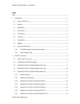
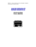
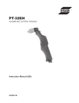
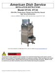
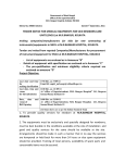
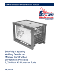
GX200 2+4
GX2
2
DC Welder
Generator
Fuel Efficient
Low Noise Level
Optional Electric Start
11 HP Honda Gas Engine
4000 Watt AC Generator
Service Manual
SVM_GX200 2+4
www.red-d-arc.com
for Serial No. 2500 and up
1-800-245-3660
Service Centers Across North America
North America's Largest Fleet of Welding and Positioning Equipment
SAFETY
Arc Welding Safety Precautions
PROTECT YOURSELF AND OTHERS FROM POSSIBLE SERIOUS INJURY OR DEATH. READ AND UNDERSTAND
BOTH THE SPECIFIC INFORMATION GIVEN IN THE OPERATING MANUAL FOR THE WELDER AND/OR OTHER
EQUIPMENT TO BE USED AS WELL AS THE FOLLOWING GENERAL INFORMATION.
1. HAVE ALL INSTALLATION, OPERATION, MAINTENANCE
AND REPAIR WORK performed only by qualified people.
2. ELECTRIC SHOCK can kill.
Protect yourself from possible dangerous electrical shock:
a. The electrode and work (or ground) circuits are
electrically "hot" when the welder is on. Never permit
contact between "hot" parts of the circuits and bare skin
or wet clothing. Wear dry, hole-free gloves to insulate
hands.
b.
Always insulate yourself from the work and ground by using dry
insulation. When welding in damp locations, on metal floors,
gratings or scaffolds, and when in positions such as sitting or
lying, make certain the insulation is large enough to cover your
full area of physical contact with work and ground.
Do not weld in locations near chlorinated hydrocarbon vapours
coming from degreasing, cleaning or spraying operations. The
heat and rays of the arc can react with solvent vapours to form
phosgene, a highly toxic gas, and other irritating products.
c.
Shielding gases used for arc welding can displace air and cause
injury or death. Always use enough ventilation, especially in
confined areas, to insure breathing air is safe.
d.
Read and understand the manufacturer's instructions for this
equipment and the consumables to be used, including the material safety data sheet (MSDS) and follow your employer's safety
practices.
e.
Also see item 9b.
4. ARC RAYS can injure eyes and burn skin.
a. Use a shield with the proper filter and cover plates to protect
your eyes from sparks and the rays of the arc when welding or
observing open arc welding. Headshield and filter lens should
conform to ANSI Z87. 1 standards.
c.
Always be sure the work cable makes a good electrical connection with the metal being welded. The connection should be as
close as possible to the area being welded.
d.
Ground the work or metal to be welded to a good
electrical ground.
b.
Use suitable clothing made from durable, flame-resistant material to protect your skin and that of your helpers from the arc rays.
Maintain the electrode holder, work clamp, welding cable and
welding machine in good, safe operating condition.
c.
Protect other nearby personnel with suitable nonflammable
screening and/or warn them not to watch the arc nor expose
themselves to the arc rays or to hot spatter or metal.
e.
f.
Never dip the electrode in water for cooling.
g.
Never simultaneously touch electrically "hot" parts of electrode
holders connected to two welders because voltage between the
two can be the total of the open circuit voltage of both welders.
h.
If using the welder as a power source for mechanized welding,
the above precautions also apply for the automatic electrode,
electrode reel, welding head, nozzle or semiautomatic welding
gun.
i.
When working above floor level, protect yourself from
a fall should you get a shock.
j.
Also see Items 6c and 8.
3. FUMES AND GASES can be dangerous to your health.
a. Welding may produce fumes and gases hazardous to health.
Avoid breathing these fumes and gases. When welding, keep
your head out of the fume. Use enough ventilation and/or
exhaust at the arc to keep fumes and gases away from the
breathing zone. When welding on galvanized, lead or cadmium
plated steel and other metals which produce toxic fumes, even
greater care must be taken.
2
b.
5. FIRE OR EXPLOSION can cause death or property damage.
a. Remove fire hazards well away from the area. If this is not possible cover them to prevent the welding sparks from starting a
fire. Remember that welding sparks and hot materials from
welding can easily go through small cracks and openings to
adjacent areas. Have a fire extinguisher readily available.
b.
Where compressed gases are to be used at the job site, special
precautions should be used to prevent hazardous situations.
Refer to "Safety in Welding and Cutting" (ANSI Standard 249.1)
and the operating information for the equipment being used.
c.
When not welding, make certain no part of the electrode circuit
is touching the work or ground. Accidental contact can cause
overheating and create a fire hazard.
d.
Do not heat, cut or weld tanks, drums or containers until the
proper steps have been taken to insure that such procedures will
not cause flammable or toxic vapours from substances inside.
They can cause an explosion even though they have been
"cleaned." For information purchase "Recommended Safe
Practices for the Preparation for Welding and Cutting of
Containers and Piping That Have Held Hazardous Substances.",
SAFETY
Highway, Arlington, VA 22202.
AWS F4.1-80 from the American Welding Society.
e.
Vent hollow castings or containers before heating, cutting or
welding. They may explode.
f.
Also see items 6c and 9c.
6. For Welding in General.
a. Droplets of molten slag and metal are thrown or fall from the
welding arc. Protect yourself with oil free protective garments
such as leather gloves, heavy shirt, cuffless trousers, high shoes
and a cap over your hair. Wear ear plugs when welding out of
position or in confined places. Always wear safety glasses when
in a welding area. Use glasses with side shields when near slag
chipping operations.
b.
c.
Keep all equipment safety guards, covers and devices in position
and in good repair. Keep hands, hair, clothing and tools away
from V-belts, gears, fans and all other moving parts when starting, operating or repairing equipment.
Be sure the work cable is connected to the work as close to the
welding area as practical. Work cables connected to the building
framework or other locations some distance from the welding
area increase the possibility of the welding current passing
through lifting chains, crane cables or other alternate circuits.
This can create fire hazards or overheat lifting chains or cables
until they fail.
7. For Gas-Shielded Arc Welding.
a. Use only compressed gas cylinders containing the correct shielding gas for the process used and properly operating regulators
designed for the gas and pressure used. All hoses, fittings, etc.
should be suitable for the application and maintained in good
condition.
b.
c.
Always keeps cylinders in an upright position securely chained
to an undercarriage or fixed support.
Cylinders should be located:
•
Away from areas where they may be struck or subjected to
physical damage.
•
A safe distance from arc welding or cutting operations and
any other source of heat, sparks, or flame.
d.
Never allow the electrode, electrode holder, or any other electrically "hot" parts to touch a cylinder.
e.
Keep your head and face away from the cylinder valve outlet
when opening the cylinder valve.
f.
Valve protection caps should always be in place and handtight
except when the cylinder is in use or connected for use.
g.
Read and follow the instructions on compressed gas cylinders,
associated equipment, and CGA publication P-1 "Precautions for
Safe Handling of Compressed Gases in Cylinders" available
from the Compressed Gas Association, 1235 Jefferson Davis
8. For Electrically Powered Equipment.
a. Turn off input power using the disconnect switch at the fuse box
before working on the equipment.
b.
Make the electrical installation in accordance with the
National Electrical Code, all local codes and the manufacturer's
recommendations.
c.
Properly ground the equipment in accordance with the National
Electrical Code and the manufacturer's recommendations.
9. For Engine Powered Equipment.
a. Turn the engine off before troubleshooting and maintenance
work unless the maintenance work requires it to be running.
b.
Operate the internal combustion engines in open, well ventilated
areas or vent the engine exhaust fumes outdoors.
c.
Do not add the fuel near an open flame, welding arc or when the
engine is running. Stop the engine and, if possible, allow it to
cool when refuelling to prevent spilled fuel from vaporizing on
contact with hot engine parts and igniting. Do not spill fuel
when filling tank. If fuel is spilled, wipe it up and do not start
engine until fumes have been eliminated.
d.
In some cases it may be necessary to remove safety guards to
perform required maintenance. Remove guards only when necessary and replace them when the maintenance requiring their
removal is complete. Always use the greatest care when working
near moving parts.
e.
Do not put your hands near the engine fan. Do not attempt to
override the governor or idler by pushing on the throttle control
rods while the engine is running.
f.
To prevent accidentally starting gasoline engines while turning
the engine or welding generator during maintenance work, disconnect the spark plug wires, distributor cap or magneto wire as
appropriate.
g.
To avoid scalding, do not remove the radiator pressure cap when
the engine is hot.
For more detailed information it is strongly recommended that you
purchase a copy of "Safety in Welding & Cutting - ANSI Standard
249.1" from the American Welding Society, P.O. Box 351040 Miami,
Florida 33135.
3
PRODUCT INFORMATION
PRODUCT DESCRIPTION
The GX200 is a portable engine driven arc welding power source
capable of providing constant current output for stick welding or DC
TIG welding.
GENERATOR
The generator of the GX200 is asynchronous with capacitor
excitation and therefore with excellent mechanical features of
sturdiness and simplicity; it requires no maintenance as it has no
sliding parts such as slip rings and brushes.
The rotor consists of a laminar pack with die cast aluminum stand.
The sizing and setting up of these active parts represent a new
principle which has made the asynchronous generator suitable for
welding services and which has been appropriately patented.
All units are equipped with low oil pressure shutdown systems.
Engines should never be operated with shutdown system
disconnected or inoperative.
GENERAL MAINTENANCE
Check all external bolts (engine mounts, generator mounts etc.) at
least once per year and tighten/replace as required.
The GX200 has a current range of 40-200 amps with a 60% duty
cycle at 170 Amps. The unit is also capable of providing 2 KVA of
120 VAC and 4KVA of 240 VAC at 60 cycle.
1 - Turn the fuel valve to the on position (turn to right)
2 - Close the choke (turn to left)
3 - Turn the throttle control knob until half open
4 - Turn the engine switch to the on position
5 - Pull the start rope lightly until resistance is felt, then pull briskly.
6 - As the engine warms up, gradually move the choke lever to the
open position.
7 - Let the engine run at low speed for 2-3 minutes to warm up.
PRE-OPERATION MAINTENANCE
ELECTRIC START
OIL
1 - Remove the oil filler cap and wipe the dipstick clean. 2 - Insert
the dipstick into the oil filler neck, but do not screw it in. 3 - If
the level is low, fill to the top of the oil filler neck with the
recommended oil.
OIL CAPACITY: 300cc ( 10 US oz.)
DO NOT OVERFILL.
Fill the fuel tank with the grade of fuel recommended.
LOCATION/VENTILATION
The welder should be located to provide an unrestricted flow of
clean, cool air. Also, locate the welder so that engine exhaust fumes
are properly vented to an outside area.
POLARITY CONTROL AND CABLE SIZES
With the engine off, connect the electrode and work cables of the
appropriate size (see the following table) to the studs located on the
front panel. For positive polarity, connect the electrode cable to the
terminal marked "Positive". For Negative polarity, connect the
electrode cable to the "Negative" stud. These connections should be
checked periodically and tightened if necessary.
When welding at a considerable distance from the welder, be sure
you use ample size welding cables.
TABLE 2
RECOMMENDED COPPER CABLE SIZES
AT 60% DUTY CYCLE
Total Combined Length of
Electrode Plus Work Cable in feet
%
Cycle
Amps Duty
1-Turn the fuel valve to the on position (turn to right) 2-Close the
choke (turn to left) 3-Turn the throttle control knob until half open. 4Turn start key switch to start. 5-As the engine warms up, gradually
move the choke lever to the open position. 6-Let the engine run at
low speed for 2-3 minutes to warm up.
TO TURN OFF THE UNIT
Turn the throttle knob in an counterclockwise direction until the
furthest position, after letting the engine run slowly for a few
seconds, turn the stop switch to the off position *IMPORTANT* Turn the fuel valve to the off position
FUEL
4
SAFETY SHUTDOWN SYSTEM
0-50
50-100
100-150 150-200 200-250
225
40
3 AWG
3 AWG
2AWG
1AWG 1/0AWG
225
100
1 AWG
1 AWG
1 AWG
1 AWG 1/0AWG
CONTROL OF WELDING CURRENT
There is one continuous current control for each range which gives
you complete adjustment of current from min. to max. within the
range. There is a low tap for ranges from 40-90Amps, a medium tap
for ranges from 90-170Amps and a high tap for ranges from 160195Amps. Always use the lowest possible range with fine current
adjustment closest to max. position.
AUXILIARY POWER
Your GX200 is equipped with AC auxiliary power.
The AC unit provides 1 X 120Volt Duplex receptacle 2KW, and 1 X
120/240Volt twist lock receptacle 4KW, at 60 Hertz power.
The output circuit is protected with a 15Amp circuit breaker for the
120V and a 15Amp circuit breaker for the 240V.
PRODUCT INFORMATION
MAINTENANCE
Have qualified personnel do the maintenance work. Turn the
engine off before working inside the machine. In some cases it
may be necessary to remove safety guards to perform required
maintenance. Remove guards only when necessary and replace
them when the maintenance requiring their removal is complete.
Always use the greatest care when working near moving parts.
Do not put your hands near the engine or generator fan. If a
problem cannot be corrected by following the instructions, take
the machine to the nearest RED-D-ARC location.
GENERAL INSTRUCTIONS
1. Blow out the welder and controls with an air hose at least once
every two months. In particularly dirty locations, this cleaning may
be necessary once a week. Use low pressure air to avoid driving
dirt into the insulation.
2. Change oil after the first 20 hours of operation. Thereafter change
the crankcase oil every 100 hours using the proper grade of oil as
recommended in the engine operating manual.
3. Oil classification SG SF/CC CD
Use viscosities as per the engine manual.
WARNING
• Do not touch electrically live parts or electrode
with skin or wet clothing. Insulate yourself
from work and ground.
• Keep flammable materials away.
• Wear eye, ear and body protection.
• Keep your head out of fumes.
• Use ventilation or exhaust to remove
fumes from breathing zone.
• Turn power off before servicing.
• Do not operate with panel open
or guards off.
• Stop engine when fuelling.
• Do not smoke when fuelling.
• Remove cap slowly to
release pressure.
• Do not overfill tank.
• Wipe up spilled fuel and allow
fumes to clear before starting engine.
• Keep sparks and flame away from tank.
5
OPERATION
CONTROL PANEL FEATURES
6
A
Grounding Screw
M
120V circuit breaker - 10A
B
Welding Socket: negative 90-170A
N
Hourmeter/Tachometer
C
Welding Socket: negative 160-195A
O
120/240V Single Phase Outlet
D
Throttle Control
P
240V signal lamp
E
Welding Socket: positive connection
Q
240V circuit breaker - 145A
F
Welding Socket: negative 40-90A
R
Start/Stop engine switch
G
Serial Number
S
Electronic battery charger
H
Stop switch
I
120V signal lamp
L
120V Single Phase outlet
circuit breaker
T
Low oil level signal lamp
OPERATION
Fuel
Consumption
Fuel consumption has been optimized by means of careful design of the combustion chamber, fuel feed & injection systems, and cross-flow cylinder heads. In order to enhance
longevity of the engine, the engine turns at a constant 3600 RPM and no engine idler is
used. As a result, there is no waiting time for the welder to achieve operating speed when
striking an arc.
Fuel consumption figures at average operating loads are as follows:
Tank Capacity
6.5 litres (1.6 U.S.gallons)
Operating Interval
Replacement
Parts
3-4 hours per tank
Engine replacement parts are available from authorized HONDA dealers.
All other parts are available from any RED-D-ARC location.
Engine
Specifications
Model
No. of Cylinders
Displacement
Rotation Speed
Power
Cooling system
Ignition system
Starting system
Optional Electric Start
PTO shaft rotation
Fuel
HONDA GX 340
1
337cc
3600 RPM
11 HP
Forced Air
Transistorized magnet
Pull start with recoil cable
Counterclockwise
Automotive gasoline
MODEL
WELDING OUTPUT
AUXILIARY OUTPUT
GX200
40-200 amps ® 25volts
90 volts maximum O.C.V.
120 Vac 15 amps
1 duplex outlet
2.0 KVA
120/240 Vac
15 amps
I single outlet
4.0 KVA
7
TROUBLESHOOTING
WARNING:
• Have qualified personnel do the troubleshooting work. Turn the engine off before working inside the machine. In some
cases it may be necessary to remove safety guards to perform required maintenance. Remove guards only when necessary
and replace them when the maintenance requiring their removal is complete. Always use the greatest care when working
near moving parts.
• Do not put your hands near the engine fan. If a problem cannot be corrected by following the instructions, take the
machine-to the nearest Red-D-Arc Location.
TROUBLE
CAUSE
WHAT TO DO
1. Engine won’t start.
A. Weather colder than -10C
B. Engine flooded.
C. Fouled spark plug.
D. Dirt or water in fuel.
E. Clogged fuel line or fuel strainer.
A. Use very light engine oil.
B. Close fuel line, drain carburetor & bowl, try again.
C. Clean or replace spark plug.
D. Drain tank and refill.
E. Drain fuel line, tank, and refill.
2. Engine runs but generator
does not produce power
at output studs and AC
outlets.
A. Unit started with load plugged in.
B. Loose connection or broken wire.
C. Welding cables shorted together.
D. Shorted diode.
E. Bad condenser.
F. Burned windings.
A. Unplug load, start engine and then plug load in.
B. Repair, mend or retighten connection
BEFORE you do any major disassembly
C. Remove short.
D. Replace rectifier.
E. Replace condenser.
F. Replace stator.
A. Broken wire to output studs
B. Opened diodes.
A. Repair.
B. Replace rectifier.
3. Engine runs well and
produces AC power but
no welding output.
8
ASSEMBLY
MISCELLANEOUS ASSEMBLY
9
ASSEMBLY
ASSEMBLY
MISC. ASSEMBLY PARTS LIST
ITEM
1
2
3
4
5
6
7
8
9
10
11
12
13
14
15
16
17
18
19
20
21
22
23
24
25
26
27
28
29
30
31
32
33
34
35
37
38
39
40
41
42
43
44
45
46
47
48
49
50
10
PART NAME & DESCRIPTION
Stator
Engine flange
Tie Rod
Rotor
Lower Stator Cover
Bearing Flange
Ball Bearing
Internal Ring
Spring Washer
Clip Ring
Fan
Fan Ring
Power Rectifier Assy.
Rectifier Cover
Tubular Frame Assy.
Shock Absorber (40x40 mms)
Shock Absorber (30x30 mms)
Spacer (H 20 mms)
Flange Tie Rod
Instrument Case
Aluminum Front Plate
Knob Cap
Throttle Knob
Throttle Cable Assembly
Ground Screw
Connection Block 6 Poles
Spacer (H70 mms)
Shock Absorber (15x30 mms)
Shock Absorber (15x30 mms)
Capacitor Support Plate
Capacitor Bracket
Capacitor 60 uF
Reactance Assembly
Right Side Cover
Lifting Hook
Air Deflector
Left Side Cover
Three Phase Reactance
Engine Support Bracket
Screw (M 5x27 mms)
Rubber Protective Cover
Circuit Breaker 15A
Spring
Resistance Coil
Resistance Support
Resistance Terminal
Male Insulator (22 mms dia.)
Insulating Washer (7 mms dia.)
Insulating Washer (12 mms dia.)
NO. REQ'D
1
1
1
1
1
1
1
1
1
1
1
1
1
1
1
2
2
2
4
1
l
1
1
1
1
1
2
2
2
1
1
3
1
1
1
1
1
1
1
5
4
4
1
1
1
4
5
10
10
PART NO.
18.335
18.281
18.279
18.280
18.278
18.642
304
305
305
307
310
311
18.377
606
RGX200FRAME
13.961
313
622
18.078
17.114
18.378
11.209
16.900
14.436
15.721
10.364
16.548
320
13.802
13.799
17.119
11.333
13.925
18.376
18.379
18.284
17.450
13.927
14.854
13.929
14.658
13.640
14.139
14.432
12.830
11.439
17.603
17.491
17.490
ASSEMBLY
MISC. ASSEMBLY PARTS LIST
ITEM
51
52
53
54
55
56
57
59
60
61
62
63
64
65
66
67
PART NAME & DESCRIPTION
Female Insulator (22 mms dia.)
Left Protection Grate
Side Plate - Left
Side Plate - Right
Top Cover
Washer
Spacer
Digital Tachometer/Hourmeter
Resistance Coil
Resistance Cover
Resistance Support
Plate
Cable Connector
12V 12Ah Battery
Battery Bracket
Battery Cover Panel
NO. REQ'D
5
1
1
1
1
4
2
1
1
1
1
1
4
1
1
1
PART NO.
17.602
13.922
17.321
15.720
17.571
14.270
18.380
TT226NR-2C
17.117
17.322
17.323
17.324
18.285
MOB-CB12B-B2
RGX200BOX
RGX200BOX
11
WIRING DIAGRAMS
12