1
VAA11801-R.3578.A
1-3. PW1 POWER CIRCUIT DESCRIPTION
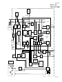
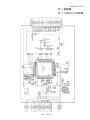
1. Power Circuit Outline
The switching regulator consists of a DC-DC converter,
and it uses a digital power supply, CCD power supply,
LCD panel power supply, LED backlight power supply
and EVF backlight power supply. The controller is used
FA7708R and TK11840L.
1-1. Switching Regulator Controller FA7708R
(IC501)
This is the basic circuit which is necessary for
controlling the power supply for a PWM-type switching
regulator, and is provided with five built-in channels.
CH1: CCD power supply circuit
CH2: digital 1.85 V power supply circuit
CH3: digital 3.35 V power supply circuit
CH4: LCD panel power supply circuit
CH5: LED backlight circuit for LCD
1. Short-circuit Protection Circuit
If output is short-circuited for the length of time
determined by the condenser which is connected to Pin
(37) of IC501, all output is turned off. The power is
restored by ON and OFF.
2. Digital 3.35 V Power Supply Circuit
Consists of a step-down type switching regulator, and
outputs 3.35 V ± 2.5 %.
3. Digital 1.85 V Power Supply Circuit
Consists of a step-down type switching regulator, and
outputs 1.85 V ± 5 %.
1-2. Switching Regulator Controller K11840L
(IC503)
This is the LED backlight circuit for EVF, and is
provided with one built-in channel.
1. Short-circuit Protection Circuit
If output is short-circuited for the length of time
determined by the condenser which is connected to Pin
(2) of IC503, all output is turned off. The power is
restored by ON and OFF.
2. LED Backlight Power Supply Circuit (for EVF)
Consists of a step-up switching regulator, and carries
out constant-current control for the LEDs.
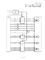
2. AC Adaptor and Battery Distinction
Differentiated by the voltage at pin 56 of the 8-bit
microprocessor. When an AC adaptor is being used,
transistor Q3010 on the SY1 circuit board is turned on,
so that pin 56 becomes low. When a battery is being
used, D3016 stops the current from flowing, so that the
transistor turns off and the voltage at pin 56 becomes
high.
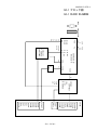
3. Battery Charging Protection Circuit
A FET (UPA1915TE) switch is inserted into the (+) end
of the battery harness so that charging current does not
flow to the battery by mistake when a battery and an
AC adaptor are being used together. When a voltage is
being generated by the AC adapter, Q5003 is turned off,
so that the battery circuit is isolated. If there is no
voltage coming from the AC adaptor, Q5003 turns on
and power is supplied from the battery.
4. CCD Power Circuit and Digital 5 V Power Supply
Circuit
15.0 V ± 0.5 V, –7.5 V ±0.5 V and 5.02 V ± 0.1 V are
output by flyback transformer (T5001). The voltage is
adjusted to 5.02 V. Digital 5 V and CCD 5.02 V are
shared.
5. LCD Panel Power Supply Circuit
Consists of a step-up type switching regulator, and
outputs 12.3 V ± 2.5 %.
6. LED Backlight Power Supply Circuit (for LCD)
Consists of a step-up switching regulator, and carries
out constant-current control for the LEDs.
- E4 ・ E5700 -