1
litiin
3173W
())1)
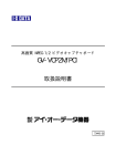
SERVICE MANUAL
FOR
SINGER*
211W151
machine
SINGLE NEEDLE
LOCK STITCH
/
2_—
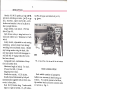
This book contains complete information covering operation
and adjustment of machine and a list of parts, accessories and
special fittings. Illustrations and descriptions of parts in rear
of book should be consulted when ordering any part of machine
requiring renewal.
THE SINGER MANUFACTURING COMPANY
© 1962 try The Singer Monrrfonturrng Con,pony
Copyright Under Irrternotionr,I Copyright Union
All RrhU Rr ,rrvrd r,rrdrr I,rtrr-Anreriron Copyright Unjon
copyright
°A Trodenrgrk of THE SINGER MANUFACTURING COMPANY
Printed in U.
S. A.
2
DESCRIPT iON
Macbin v 21 1 W 151 produces high speed,
precision stitching on coats, suits, over—
ails, rainwear, sports oute rwear, work
do the s and si m liar itt’ m s of medium to
heavy weight fabrics.
Single needle, lock stitch. l’tdtral
Stitch Type 301.
Beit driven rotary sewing hook on ver
tical axis makes two revolutions for each
stitch.
Safety clutch, adjustable to suit sewing
conditions, prote cts hook from damage
resulting from accidental strain. Should
any foreign matter clog the hook, this
new type safety clutch will disengage it
self and will re-engage only after area
has been cleared.
Compound feed, combination of drop
feed and needle feed.
Maximum length of stitch, 5 to inch.
Presser bar lift, 1/4 inch.
Hinged presser foot.
Needle bar stroke, 1-5/16 inches.
Needle thread lubricated by felt pad
automatically supplied with oil from res
ervoir in face plate.
Bed, 20-3/8 inches long, 7 inches wide.
Space at right of needle, 10-1/2 inches.
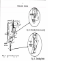
hole in drip pan and attach oil jar D,
as shown.
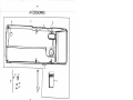
Fig. 2. Knee Lifter, Drip Pan ond Oil Jar In Position
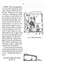
HOOK LUBRICATION
Hook saddle contains oil pumped to
bobbin case raceway in hook during op
eration. To control amount of oil flow,
tip machine back and loosen control valve
set screw A, Fig. 3.
SPEED
Maximum speed, 4000 R. P. M., depend
ing on material being stitched. It is ad
visable to run a new machine slower than
maximum speed for first few minutes to
allow time for oil to reach moving parts.
Machine pulley turns over toward operator.
SETTING
UP
Fasten drip pan to table with its left end
evenwith left end of cut-out. Fasten knee
lifter bracket in location shown in Fig. 2.
Assemble it so that lifter rod A does not
strike drip pan. Screw slots in bracket
provide necessary adjustment. Set stop
stud B to stop action of knee lifter as soon
as presser foot is raised enough to trip
hand lever. Screw drain pipe C into drain
Fig. 3. Sewing Hook Oil
Control Valve Set Screw
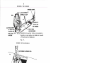
Fig. 4. Sewing Hook
Oil Control Valve Screw
Return machine to upright position.
Turn control valve K to right for more oil;
to left for less oil.
After desired adjust
ment is attained, re-tighten control valve
set screw A. See complete lubricating
instructions next.
3
LU KRICATJON
CLEANING
Use SI NGER OIL, ‘‘I’YI-i A’’ or
‘‘TYPI C’’. Use ‘‘TYPE C’’ OIL when
an oi[ is desired which will produce
minimum stain on fabrics even after
long period of storage.
CLean out all lint and other waste from
around sewing hook and between feed
rows on underside of throat plate.
FILl. THREAD LUBRICATOR
RESERVOIR WITH
HIGH MARK
FILL RESERVOIR
SI NGER*
THREAD LUBRICANT
“TYPE E”
ON
WHEN MACHINE
IS RUNNING—
—
(CHECK TWICE DAILY)
T L_-
OFF
WHEN MACHINE
IS IDLE
FOR
MORE
THREAD
LUBRICANT
-
Fig. 6. Reservoir in Arm
LUBRICATING PAD
Fig. 5. LubricatIng Nachine Head
FILL RESERVOIR
TO HIGH MARK
CHECK TWICE DAILY
/
HIGH MARK
C-.’
SATURATE WICK
OIL TWICE DAILY
Fig. 7. Reservoir in Bed
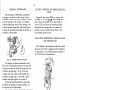
NEEDLES
Use SINGER* Needles
Catalog 1901 (135x7)
when machine is set with 1/4” clear
ance under presser foot
or
Catalog 3355 (135x17)
when machine is set with 3/8” clear
ance under presser foot
Needle sizes determined by size of
thread and type of material being sewn.
MOVE TO
HIGHEST POINT
LONG
TO
LEFT
LOOSEN SCREW
INSERT NEEDLE UP
AS FAR AS POSSIBLE
AND TIGHTEN SCREW
jg. 8. Setting the Needle
4
THREADING
NEEDLE
Fig. 10. Threading Tension Assembly
OIL PAD
Fig. 9. Upper Threading Complete
Fig.
BOBBIN
REMOVAL
RAISE LATCH
BOBBIN
7
Fig.
12.
11. Threading Needle
5
TI-IF BOBBIN
WINDING
TENSION CONTROL
1. PLACE BOBBIN ON
SPINDLE AS FAR
AS IT WILL GO
OIL
LOOSEN TO
ADJUST FOR
EVEN WINDING
3. PRESS DOWN
TO PUSH PULLE
AGAINST BELT,
2. WIND THREAD
AROUND BOBBIN
N0TETIGHTEN FOR MORE THREAD ON BOBBIN:
Regulate to stop winder when bobbin is wound
1/16 inch short of bobbin rim
THEN START
MACHINE
Fig.
BOBBIN
13.
REPLACEMENT
PLACE BOBBIN ON CENTER STUD
2
CLOSE LATCH
I,
DIRECTION OF THREAD
AROUND BOBBIN
Fig.
THREADING
14.
BOBBIN CASE
DRAW THREAD TO
BACK OF PROJECTION
DRAW THREAD UP
TWO INCHES
Fig. 15.
Fig.
16.
6
THREAD
TENSIONS
Turn machine pulley until tension
screw is accessible.
Regulate needle thread tension only
when presser foot is down.
MORE
TENSION
MORE TENSION
LESS TENSION
<-..
Fig. 17. Hobbin Thread Tension
Tension on threads should be as light
as possible while still sufficient to set
Fig. 18.
stitch in material.
STITCH LENGTH REGULATION
1. Stop machine 2. Depress button shown in Fig. 19
3. Turn machine pulley toward you
slowly— until button drops (clicks).
4. Turn machine pulley until desired
stitch length is opposite mark on
arm (see Fig. 20 ).
5. Release button.
Needle Thread Tension
Fig. 20. Stitch Length
Indicator
Never depress the button while the
machine is running.
Make certain that plunger is disengaged
before starting machine.
BUTTON
Fig. 19. Stitch Length Button Regulator
PRESSER FOOT
PRESSURE
TURN TO
ADJUST
The pressure on the material should be
as light as possible, while still suffi
cient to insure correct feeding.
Fig. 21. Adjusting Pressure
7
THREAD
CONTROLLER
The function of the thread controller
spring is to hold back the slack of the
needle thread until point of needle reach
es the goods in its descent, as without
this controlling action of the spring, the
slack thread (especially silk) will some
times be penetrated by point of needle as
needle is descending.
TO SET A NEEDLE BAR WHICH HAS NO
MARK
Regulate the stitch length as instructed
on page 6, so that there is no feeding mo
tion, then set needle bar so that when it
rises 3/32 inch from its lowest position
and point of sewing hook is at center of
needle, eye of needle will be about 1/16
inch below point of hook.
RELATIVE POSITIONS OF NEEDLE BAR
AND PRESSER BAR
The distance between the needle bar and
presser bar (after regulating stitch length
so that there is no feed movement) should
be 17/32 inch as shown below.
Fig. 22. Adjustment of Thread Controller
To change the thread controller stop
for more controller action on the thread,
loosen set screw Z, and turn thread con
troller spring stop T, Fig. 22 to the
right; for less action, turn thread con
troller spring stop T to the left, after
which securely tighten set screw Z.
It may be found advisable to increase
tension of spring for coarse thread, or
to lessen it for fine thread.
To increase tension of thread controller
on thread, loosen tension stud set screw
Y, located nearly under tension stud, and
turn tension stud AZ slightly to the left.
To decrease tension turn it to the right.
Re-tighten stud set screw Y.
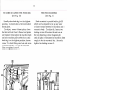
TO SET NEEDLE BAR
See that needle is up in the holder as
far as it will go. There are two lines
across the needle bar about two inches
above the lower end. When needle bar
is at its lowest position, the upper mark
should be just visible at end of needle
bar frame.
In case needle bar is not correctly set,
loosen needle bar connecting stud pinch
screw M, Fig. 23 and place needle bar
in correct position as directed above,
then re-tighten screw M.
Fig. 23. Relative Positions of Needle
Bar and Presser Bar
If the distance between needle bar and
presser bar is more or less than 17/32
inch, loosen needle bar frame shaft clamp
screw NZ, Fig. 24. While this screw is
loose, needle bar frame can be moved for
ward or backward, as may be required,
N2
Fig. 24. To Adjust Needle Rook Frame
S
until the distance between the needle bar
and presser bar is 17/32 inch. A piece
ol. sheet metal 17/32 inch wide may be
llse(1 to det. rnine the correct distance.
When the adj ustinent has been made,
securely tighten screw NZ.
TO ADJUST HEIGHT OF
SEWING HOOK
When lower timing mark A, Fig. 26 on
needle bar is just visible at end of needle
bar frame on upward stroke of needle bar,
the hook point should be about 1/16 inch
above eye of neecUc, as shown in Fig. 26.
To adjust height of hook, fasten throat
plate to bed of machine with bobbin case
stop finger K, Fig. 26, in sewing position.
Use 032 inch shim. Shim should slide
between bobbin case stop finger K and
throat plate. If the shim is too loose,
turn machine pulley so that socket screws
hook so that a hole in bobbin case is in
line with hook height adjusting screw J2,
Fig. 25. To raise hook, turn down screw
J2. if there is insufficient space for the
shim to pass between bobbin case stop
finger K and throat plate, turn up screw JZ
and press down hook. Check timing and
tighten socket screws HZ, then turn screw
JZ just enough to leave a light tension.
TO SET SEWING HOOK TO
OR FROM NEEDLE
N
.
J2
Fig. 27. Adjustments Underneath the Nachine
Fig. 25. Height Adjustment of Sawing Hook
HZ, Fig. 25 are accessible with a socket
wrench. Loosen both screws and remove
cloth washer from bobbin case, then turn
To prevent point of hook from dividing
strands of thread, it should pass as close
as possible to the needle (within the clear
ance above needle eye).
Turn machine pulley over toward you
until point of sewing hook is at center of
needle. Loosen screws N and T, Fig. 27,
underneath bed of machine and move hook
saddle to the right or left, as may be re
quired, until point of hook is as close to
needle as possible without striking it, then
securely tighten screws N and T.
CAUTION: Make sure hook driving gears
U, are set correctly with relation to face
of hook saddle. Use 008 shim.
The function of hook washer (needle
guard) GZ, Fig. 25, which is attached to
bottom of sewing hook, is to prevent point
of hook from striking needle if, when pass
ing through material, needle is deflected
toward hook.
The needle guard can be bent with a small
pair of pliers until it prevents hook point
from striking needle, but it should not be
bent outward enough to deflect needle from
its normal path.
.
Fig. 26. Height Adjustment of Sewing Hook
9
‘10 l’IM1 SEW[NG HOOK
on
Regulate tin stitch length, as instructed
JiLg 6,
so that there i s no feeding mo
TO REMOVE BOBBIN CASE
FROM SEWING I-lOOK
(see Fig. Z9)
—
tiun
Remove throat plate and turn machi tie
pulley over toward you until lower mark
across needle bar is just visible at end
of needle bar frame on upward stroke of
needle bar, as shown in Fig. 26. If
needle bar and sewing hook are correctly
timed, the point of hook will be at center
of needle (about 1/16 inch above the eye)
as shown in Fig. 26.
Remove the two hook gib screws W,
from sewing hook, lift oil hook gib F2,
and remove bobbin case X.
x
Fi(;. 29. To Remove Bobbin Case from
Sewin; Hook
TO REMOVE SEWING HOOK
FROM MACHINE
Remove presser foot, throat plate and
feed dog, then loosen two socket screws
in hub of hook HZ, Fig. 30 and lift hook
off end of shaft. To remove hook shaft,
first remove screws in ball bearing re
J2
Fj. 28. Timin Sew1n Hook
In case sewing hook is not correctly
timed, turn machine pulley over toward
you until needle bar has descended to
its lowest point and has risen to the po
sition
where
lower timing mark
across needle bar is just visible at end
of needle bar frame, as shown at A,
Fig. 26. Loosen two socket screws in
hub of hook shaft gear L2, Fig. 28 and
turn hook until point of hook is at center
of needle. Then securely tighten two
socket screws in hook shaft gear L2.
Fig. 30. To Remove Sewinc hook from Machine
taming cap directly under hook. Next,
tip machine back and loosen set screws
L2, Fig. 28 in hook shaft gear and lift
hook shaft by top end. If shaft does not
lift out easily, loosen screws in cover
plate of hook saddle sufficiently to per
mit oil to drain out, then remove cover,
being careful not to damage the gasket
MZ, Fig. 32, page 10, then tap end of
hook shaft.
10
CAUTION: The hook is equipped with a
screw in the hub for adjusting the vertical
position of the hook relative to the throat
plate seat. This position is set to a gauge
at the factory. When replacing or install
ing a new hook, care must be taken to see
that the bobbin case stop finger K, Fig. 31
fits correctly in the throat plate. If it is
too high, it will interfere with the free
passage of thread. If it is too low, it may
slip out and cause damage to hook and
bobbin case when machine is in operation.
To make the adjustment, remove cloth
washer in bottom of bobbin case, loosen
socket screws HZ, Fig. 30, page 9 in hook
hub, then turn hook until adjusting screw
appears beneath one of the holes in the
bottom of bobbin case. Hold hook down
against its seat and turn adjusting screw
with screwdriver until the proper up and
down position is attained. Tighten socket
screws HZ, Fig. 30 in hub of hook.
To remove ball bearing from hook shaft,
rest bearing with shaft-end up on two pieces
of sheet metal placed across the open jaws
of a vise. Tap shaft until bearing is re
moved.
Y
E2
D2
C2
Fig. 31. Adjusting Bobbin Case Opener
TO ADJUST BOBBIN CASE OPENER
(see Fig. 31)
The bobbin case opener Y should be
set so that it touches the bobbin case as
lightly as possible, yet turns the bobbin
case enough to make a sufficient open
ing for the free passage of the thread be
tween throat plate and bobbin case.
TO TIME BOBBIN CASE OPENER
(see Figs. 31 and 3Z)
Turn machine pulley over toward you
until lower timing mark on needle bar is
even with end of needle bar frame on up
ward stroke of needle. In this position,
the mark DZ, on flange of opener driving
shaft, should line up with reference mark
CZ on hook saddle. If opener shaft is out
of time, tip machine back and loosen
Fig. 32. Timing Bobbin Case Opener
socket screws KZ in opener driving gear
then return machine to upright position
and turn shaft with screwdriver in screw EZ
at top end of shaft, then tighten socket
screws KZ in gear.
11
TO RAISR OR LOWVR THE FEED DOG
(see Fig. 33)
THE FEED ECCENTRIC
(see Fig. 34)
Usually when feed dog is at its highest
position, it should show a full tooth above
throat plate.
To adjust, remove throat plate; clean
the lint and dust from between feed points
and replace throat plate; tip machine back
and turn machine pulley toward you until
feed dog is at its highest position; loosen
screw V in feed lifting cam fork and raise
or lower feed dog, as may be required.
Then re-tighten screw V.
Feed eccentric is provided with a gib P2
which can be adjusted to take up any wear
or loose motion between feed eccentric and
eccentric body. To adjust gib, loosen two
locking screws 02 nearest gib and turn in
the two adjusting screws 02 against gib
until all play is eliminated and eccentric fits
snugly in slot in eccentric body. Securely
tighten two locking screws QZ.
B3
Fig. 33. Feed Adjustments
When raising or lowering feed dog, be
careful that its underside does not drop
low enough to strike sewing hook.
Feed dog should be set so that when
needle is down it will be slightly in front
of center of needle hole in feed dog. In
case needle is not correctly located in
needle hole, loosen pinch screws B3
and adjust feed dog as required. Then
securely tighten pinch screws B3 and
check relative position of the needle
bar and presser bar as instructed on
page 7.
Fig. 34. Feed Eccentric
Spring R2 presses against feed eccen
tric cam to prevent it from moving out
of position while machine is operating.
Collar S2 may be moved to right or left
to change spring pressure. It should
ordinarily be set flush with end of hub
of eccentric body.
12
TO RLMOV1 NEEDLE BAR ROCK FRAME
Open the fact plate. Remove take— up
hinge stud L, Fig. 23, page 7, and Lake—tip.
Remove cover plate on front upright por
tion oi arm and loosen needle bar rock
frame rock shaft connection pinch screw
N2, Fig. 35. Pull needle bar rock frame
with its shaft from machine.
TO REPLACE ARM SHAFT
CONNECTION BELT
(see Fig. 37)
Remove needle to avoid damage while ma
chine is out of time. Slide belt off lower
pulley XZ. Loosen two screws in machine
pulley and remove machine pulley and ball
bearing which comes out with the pulley.
Lift belt up and draw it around arm shaft
through space at M2, Fig. 36, normally
occupied by ball bearing.
\
Fig. 33. To Remove Needle Bar Rock Frame
Fig. 37. To Replace Arm Shaft Connection Belt
TO REMOVE TAKE-UP LEVER
Remove arm cover on top of
Loosen set screw U2, Fig. 36,
move take-up lever hinge stud
page 7. Lift take-up lever out
slot VZ in top of arm.
V2 U2
Fig. 36. To Remove Take-up Lever
machine.
and re
L, Fig. 23,
through
T2
Replace belt through ball bearing hole at
MZ, Fig. 36, After placing belt over upper
pulley TZ, Fig. 36 replace machine pulley
with ball bearing. To remove all end play
from shaft, lightly tighten set screws in ma
chine pulley and (holding needle bar crank
in place) tap machine pulley into position
with palm of hand. Tighten machine pulley
set screws firmly.
Turn machine pulley over toward you un
til thread take-up lever is at its highest
point. Then turn hook driving shaft until the
“B’ setting mark at Z2 on safety clutch in
pulley X2 is in line with mark Y2 cut into ma
chine bed. Now, without disturbing either
arm shaft or hook driving shaft, slip belt
over lower pulley. The feed will then be
correctly timed with needle.
NOTE: Safety clutch in lower belt pulley
XZ has been set at factory for correct torque
and must not be disturbed.
13
PARTS LIST
FOR
SINGER
211w151
MACHINE
Parts marked with a diamond (+) are furnished only when repairs are
made at the factory; these (+) parts are named at bottom of descriptive
list opposite illustration.
14
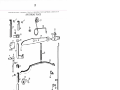
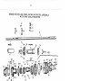
ARM SI-LAF’T, NEEDLE BAR AND TAKE-UP ASSEMBLY
R I.
No.
1
2
3
1
5
6
7
8
9
10
11
12
13
1 L1
15
16
17
18
19
20
21
22
23
25
26
27
28
29
30
31
32
33
31*
35
36
37
38
39
Part
No.
Zi01 39
267239
235706
200383 C
Description
Likc”-iip Lever
hinge Stud with 235706
Oil Packing (wick)
Hinge Stud Set Screw
202552
Connecting Link
Driving Stud with 2i071
202399
LO7 1
1
2L
Oil Packing (wick)
26i7 1
Connecting Stud with 200072C and 202330
Pinch Screw
20007 ZC
202330
Oil Packing (wick)
267160
Oil Pad (felt) (upper)
267236
Oil Reservoir Oil Wick
267247
Arm Shaft +267158 with 200333C, 200347AL, 200378C,
200388C, 267221 and +267Z22
267221
Connecting Link Stud with 267466
267466
Oil Packing (wick)
20037AL Set Screw
200388C
Set Screw
200333C
Position Screw
200378C
Position Screw Check Screw
267221
Friction Washer
L7L+7
1
2L
Arm ShMt Bushing
2 0i 329
Oil Pad (felt) (lower)
2003LlC
Set Screw
267162
Belt Pulley with 200363AL, 350492C and two 202253
202253
Spring Flange
350’+92C
Position Screw
200363AL
Set Screw
267161
Connection Belt (reinforced neoprene)
2L722
Machine Pulley 2L72l with 27211*2
2L721
Machine Pulley (aluminum alloy ca;ting) for “V” belt
(outside diam. of belt groove 2.9 in.) (rim diam.
+
1
in.) (inside belt groove) with l1*1566C and l’il567C
l1*1566C
Position Screw
l1*l567C
Set Screw
27211*2
Bearing (back) (double shielded bearing)
21*0020
Needle Bar with ZOO125ALX, 200l75D and 21*0039
ZOO1Z5ALX Set Screw
200l75D
Needle Bar Thread Guide Screw
21*0039
Needle Bar Thread Guide
21*1*726
Take-up Lever Guard
20l31*lC
+267158
+267222
Guard Screw (3)
Arm Shaft
Needle Bar Crank
15
ARM SHAFT, NEEDLE BAR AND TAKEU ASSEMBLY
4
1
r
6
38
n
7
12
16
14
}13
29
31
26
30
33
24
21
27
34
—
— —
35%
37—
36
ll
16
LUBRICATION DEVICE, BED SLIDES, COVERS AND MISCELLANEOUS PARTS
Ref.
No.
I
2
Part
No.
3
15
16
17
18
19
20
21
22
271017
Z0l525E
267272
267395
i705
1
2i
20007D
268197
267220
201313F
267388
0003
1
2L
2OOO
223811
223812
2OLZ35
20O90&E
202005
267152
350563E
26700
23
267396
25
26
27
28
237D
267397
200l33E
267398
267399
1_I
5
6
7
8
9
10
11
12
1 3
2lr751
Z000Li7X
+244701
+244702
Description
Arm Cover (top) with 267272
Screw (6)
Thread Guide (top of Arm)
Lock Nut
Oil Level Indicator
Gasket (vellumoid)
Face Plate
Face Plate Screw (2)
Needle Bar Connecting Link Oil Guard Lock Plate
Oil Guard
Screw (2)
Tension Release Lever Rod Tube
Bed Slide (back)
Bed Slide (front)
Stop
Spring
Arm Position Pin (2)
Arm Screw (4:)
Washer ()
Arm Cover (side)
Screw
Dynamic Head End Lubrication Device complete, Nos. 267396
267397, 267398, 267399 and five 237D
Oil Vibrating Pump Block
Oil Vibrating Pump Screw(S)
Oil Vibrating Pump Bracket
Oil Vibrating Pump Bracket Screw (Z)
Oil Vibrating Pump Weight
Oil Vibrating Pump Weight Spring
Arm with 267388
Bed
17
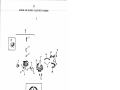
LUBRICATION DEVICE, BED SLIDES, COVERS AND MISCELLANEOUS PARTS
_r__1
()
/
3
1°
1
5
2
0
jO
01
o
21
/)
12
I
_j
1o
20
19
22
23
24
26
24
__,/
27
24
14
F:
—
0
13
I,
18
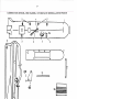
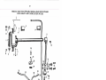
PRESSER BAR, PRESSER FOOT, PRESSER FOOT LIFTING ASSEMBLY
ANT) Ti-IROAT PLATE
Ref.
No.
1
2
3
4
5
6
7
8
9
10
11
12
13
14
15
16
17
18
19
20
21
22
23
24
25
26
27
28
29
30
31
32
33
34
35
36
37
Part
No.
Description
208566
Presser Bar with 200074F
20007’+F
Screw
207072
Presser Bar Bushing (2)
ZOO35ZALX Set Screw.(3)
210949
Spring Bracket with Z00086ALX
Z00086ALX Pinch Screw
267238
Releasing Lever Bracket
202671
Presser Bar Lifter
200653C
Hinge Screw
206608
Releasing Lever Bracket Spring
202401
Take-up Lever Oiling Felt
200132E
Oiling Felt Screw
202338
Guide Lever with Z00086ALX
Z00086ALX Pinch Screw
202337
Position Guide
200738X
Spring Stop Screw
35046+X
Lever Hinge Screw
267289
Lifting Lever Spring
240068
Lifting Lever
240067
Connection Lever
200262X
Hinge Screw
267251
Spring (flat)
350581C
Spring Regulating Screw
200948F
Spring Support Screw
20097SF
Lever Bracket Guide Screw
267265
Lever Rod
240564
Lifting Rod
227227
Lifting Rod Stop Collar with 200 113F
200113F
Set Screw
275050
Presser Foot (hinged) complete, Nos.202090, 203013
and 275049
275049
Shank with 200355X and 201537X
203013
Plate
202090
Hinge Pin
200355X
Plate Stop Screw
201537X
Stop Screw Lock Nut
240025
Throat Plate
691F
Throat Plate Screw (2)
19
PRESSER BAR,
PRISS1R FOOT, PRESSER FOOT LIFTING ASSEMBLY
A N I) TiIROAT PLATE
IS
,15
14
ir
cD
2O
13
‘Ji
12-0
23
9
.J
4
27
I
1
28
36
30
33
34
32
29
20
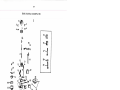
TENSION COMPLETE, THREAD GUIDES AND THREAD LUBRICATOR
Ref.
Part
No.
1
No.
21+ L1 727
2
21+0023
3
201Z21+X
1+
5
236060
223703
6
200309E
Z23706
350588X
223701+
Z1+1+0’*8
201+271
2231*38
Z01572X
267368
ZO1199F
201+925
21+1+729
200l59F
267315
267316
Z00582X
Z00337C
21+1*71+5
7
8
9
10
11
12
13
11+
15
16
17
18
19
20
21
ZZ
23
21*
25
26
21+1+735
Z011+02X
21+1+731*
27
28
29
30
31
32
33
31*
35
36
37
38
39
1*0
L+1
1*2
1*3
1*1*
21+1*71+1*
200582X
21*17 65
263551*
ZOO1L+3X
21+1*737
21*1+738
1623X
21*1*71*3
201738X
21+1*71+6
201750X
21*1*739
21*1+71*2
21*1*71*0
267323
21+1*71*1
21*1+736
Des c ription
Tension Bracket complete, Nos.201199F, 201+271,Z231+38,
223703, 223701+, 223706, 21+0023, 267315, 267368, 350588X,
two each 200309E, 201572X and 21*1+01+8
Tension Bracket with 20122
-+X and 236060
1
Tension Stud
Tension Disc Position Pin
Tension Release Lever
Release Lever Screw
Thread Controller Disc
Controller Disc Screw
Tension Release Plunger
Tension Disc
Tension Release Washer
Tension Spring
Thumb Nut
Thread Controller Spring
Thread Controller Stud with 201+925
Thread Controller Stud Washer
Thread Retainer
Tension Bracket Screw
Thread Controller Spring Stop
Thread Guide
Guide Screw
Thread Controller Stud Set Screw
Thread Lubricator complete, Nos. l623X, Z0l738X, 20l750X,
21+1+731* to 21*1+71+3, 267323,two Z1+1+7L6 and six ZOl1*OZX
Thread Lubricator Oil Reservoir Cover
Cover Screw
Thread Lubricator Oil Pad Holder complete, Nos, 21*1765,
21+1*71+1*, 263551+ and two 200l1*3X
Thread Lubricator Plate
Plate Screw (2)
Thread Lubricator Oil Pad (felt)
Oil Pad Holder
Pad Holder Screw
Thread Lubricator Oil Socket
Socket Lock Nut Washer
Socket Lock Nut
Oil Tube
Tube Nut
Socket Oil Seal
Plunger Adjusting Nut
Socket Plunger
Plunger Spring
Plunger Oil Seal (rubber)
Plunger Release Lever Pin
Plunger Release Lever
Reservoir Cover Gasket
21
TENSION COMPLETE, THREAD
GUiDES AN1) THREAD LUBRICATOR
10
12
17
61:jf
‘%
16
20
21
23
24
32
35
34
2
-‘j:
.37
38
40
°‘°
30
41
43
36
LOWER FEED ASSEMBLY WITH FEED DOG
R(.c.
No.
1
Part
No.
Z11i709
2
21+0221+
Description
Feed l)riving Rock Shaft 21+1+7 08 with Z01518E, 21+0221+,
21+1+707 and 350393C
Feed Bar 21+0223 with 225837, 267273 and 350197E
3
1+
5
6
7
8
9
10
11
12
13
21+1+708
350393C
Z0l5l8E
2-i0223
21+1+707
350l97E
225837
267273
223655
200173D
21+0259
200106E
21+1+730
200036E
202625
200383C
2’+1+71o
200029E
200051+C
200398C
267031+
267032
268063
267031
270653
20Z251+
2+371+1+
350366X
Rock Shaft
Hinge Screw (driving)
Nut
Feed Bar
Feed Driving Rock Frame with two 200036E
Fork Screw
Washer
Eccentric Fork with 200l73D and 223655
Oiling Felt
Screw
Feed Dog, 1+0 needle hole,for needle size 20 and 22
Screw (Z)
Bushing (left and right)
Rock Frame Pinch Screw
Stop Collar with two 200383C (2)
Set Screw
+C and 200398C
1
Crank with 200029E, 20005
Pinch Screw
Pinch Screw
Set Screw
Hinge Stud
Connection Z67031 with 268063 and 270653
Needle Bearing
Connection
Needle Bearing
Oil Wick (2)
Gasket (2)
Oil Stop Screw (2)
11+
15
16
17
18
19
20
21
22
23
21+
25
26
27
28
29
30
23
LOWER FEED ASSEMBLY WITH FEED DOG
14
13
‘—1
12
-
f
i
2
4
22
28
19
29
3o—
5____ 30
24
HOOK DRIVING AND FEED 1)RIVING ECCENTRIC ASSEMBLY
WITH HOOK SADDLE BEARINGS
Ref.
N0
1
2
Part
No.
Z02Z5-i
2672L+5
3
270026
1
OZL5
1
ZL
5
6
7
8
9
350i0X
27l2
263093
Z7l5
267182
10
11
12
13
1
1L
15
16
17
18
19
20
267188
ZOO38ZALX
2O1Z2OALX
2&718
7
1
2238L
267033
200582X
26806L
267623
35058C
267180
21
22
23
ZL&l763
35077C
350L&67C
268065
268066
268067
2Lj1+711&
267190
713
1
21*L
267063
200580X
244760
202253
140 197AL
244761
244762
1Z58AL
1266AL
244763
244764
244759
25
26
27
28
29
30
31
32
33
34
35
36
37
38
39
40
41
Description
Wick (2)
Feed Regulating Stud
Spring
Retaining Spring
Bed Oil Screw
Driving Shaft
Driving Shaft Bearing Packing (wick)
Driving Shaft Bearing (left)
Feed Lifting Eccentric with 201220ALX
Gear (spiral) with ZOO382ALX and 2O1ZZOALX
Set Screw
Screw
Saddle Bearing (right)
Saddle Bearing Oil Packing Wick
Friction Washer
Screw (3)
Feed Driving Eccentric
Friction Plate
Screw
1
2
67C,35077C,
763,350
Flange with 267623,two each 1
and 3505&8C
Set Screw Packing (brass)
Set Screw
Set Screw
Adjusting Disc
Spring
Collar with two 200382ALX
Collar 267190 with 2&k713
Collar with 200382ALX and 2O1ZZOALX
Ball Bearing
Retaining Washer
Screw (3)
Safety Clutch and Belt Pulley with 202253
Spring Flange
Safety Clutch Overload Pulley Set Screw
Safety Clutch Overload Pulley with two 140197AL and three 1Z58AL
Safety Clutch Driving Ball Spring
Safety Clutch Overload Pulley Adjusting Screw
Safety Clutch Overload Pulley Adjusting Screw Lock Screw
Safety Clutch Retaining Ring
Safety Clutch Driving Ball
Safety Clutch and Belt Pulley, Complete
1 &°
9C
L Cf
cQ
6E
CC
/
OC
[C
9;
c;
6?
[[
\
[[
U
L7
BE
‘
/1)
Ii
Pt
6
Cl.
c[
Il.
L
i)
-
9
P
—
SDNI’dV iaav TOOH HLIM
A[{WgSV DIIJMDD OMIAIHa UT GNV DNIAI’thJ NOOH
c?
1-TOOK AND BOBBIN CASE WITH BOBBIN
Ref.
No.
Part
No.
1
2
1
2
+
711
i
235100
3
1+
5
6
7
8
9
10
11
12
13
20361+8
2031+73
2031+71+
203216
203211+
20098L+C
200591+E
21+1671+
21+1675
3501+05C
267356
j14
15
16
17
18
19
20
21
22
Description
Flook and Bobbin Case complete, Nos 235100 and 267356
Bobbin Case complete,Nos.Z0059LiE,20098L1C,*202056,
20321k, 203216, 203173, Z03i7Li, 2036’iS, +235099,
05C
1
2+1671i, 2-iJ675 and two 350L
Bobbin Case Latch
Latch Plunger
Latch Spring
Washer (cloth)
Tension Spring
Tension Spring Regulating Screw
Tension Spring Screw
Oiling Felt
Retainer
Screw
Hook +267355 with 267358 to 267360, 35057
+F, two each
1
200591X, 201253F and 2011+09F
Hook Height Adjusting Screw
350571+F
11+0L+31+ALX Set Screw
267360
Thread Guard
200591X
Screw
Needle Guard
267359
2011+09 F
Screw
Hook Gib
267358
201253F
Screw
21+1+750
Bobbin
+202056
+235099
+267355
Bobbin Case Latch Pin
Bobbin Case (chromium plated)
Hook (sewing) with two 11+01+31+ALX
Cr4
k)
0
‘o__
cJ1
‘0
‘C.)
JS)
‘-4
0
H
CID
C
z
0
0
0
28
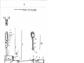
HOOK SADDLE COMPLETE
Ref.
No.
1
2
3
5
6
7
8
9
10
11
12
13
15
16
17
18
19
20
21
22
23
25
26
27
28
29
30
31
32
33
31
35
36
37
38
39
Part
No.
2*720
Description
Hook Saddle complete, Nos.200110D, ZOO37LiALX,200378C,
200388C, 2Li08, 2i70Li, 21I*711, 267053, 267166, 267167,
8,
1
, 267198, 267200,267212, 267215, 2672L
1
L
9
267172, 2671
267351,267365,267366,35056L&E,two eachZ00089X,
Z00135C, 267361 and eight Z00061ALX
2iLi711
Hook and Bobbin Case complete
Hook Ball Bearing
267053
Retainer
267361
Screw
200089X
Oil Wick Holder
276061
Oil Wick
270880
Hook Shaft with 270880 and 276061
267215
Link
267172
Cap Screw
200135C
2L70
Cam Shaft
Pinion (spiral) with two 350595XC
267366
Set Screw
350595XC
Oil Regulating Screw
E
1
35056
Hinge Stud
267167
Opener Crank
267166
Bobbin Case Opener
267351
Screw
200110D
Pinion Thrust Bearing
Z6728
Hook Shaft Bushing
267367
L
9
267l
Hook Saddle with 200 185D, 267367, 267370 and 267371
Cam Shaft Bushing (upper)
267371
Cam Shaft Gear (spiral) with two 350595XC
267365
Cam Shaft Bushing (lower)
267370
Oil Regulating Screw Check Screw
200378C
Check Screw Packing (fibre)
Oil Stop Screw
200185D
20037L&ALX Hinge Stud Set Screw
200388C
Check Screw
Z67198
Oil Gauge Sleeve with 267277
Oil Strainer
267277
Gasket
267212
Oil Reservoir
267200
20006 1ALX Sc rew
Pinch Sleeve (upper)
2671i0
Pinch Sleeve (lower)
267139
Screw
200001E
Washer
225585
Hook Saddle Screw
200006E
C)
C.)
C.)
I
7
‘)
c)
•
0
C.)
0’
1
—
o
0
—
t::j
t:tl
H
C
t:1
C)
Cr1
C
C
0
30
NEEI)LE BAR ROCK FRAME, NEEDLE BAR ROCK FRAME
ROCK SHAFT AND LUBRICATING WICKS
Ref.
No.
1
Part
No.
267286
2
3
L
0
1
025
267287
200587D
267231
267233
267232
200176E
267362
200398C
267229
200029G
267230
350566C
202277
201517E
2LjLf725
267 25L+
267276
*C
1
20003
267293
267257
5
6
7
8
9
10
11
12
13
15
16
17
18
19
20
21
22
23
25
26
27
28
29
30
31
32
267263
267321
267322
21+Liz7l6
27l7
ZLkLI7O6
267Z61
2-&*719
267262
267256
•267281
+267285
Description
0025
1
Needle Bar Rock Frame Rock Shaft •267285 with L
and •26728+
Position Pin
Wear Plate
Screw
Oiling Felt
Retainer (lower)
Retainer (upper)
Screw (i-i)
Rock Shaft Bushing (2)
Set Screw
Connection with 200029C
Pinch Screw
Link
Hinge Screw with 202277 (2)
Packing (wick)
Nut (2)
Rock Shaft Crank with 200029C and 200398C
Bed Oil Tube Clamp
Clamp Oiling Felt
Screw
Feed Driving Eccentric Connection Oil Tube Support
Feed Driving Rock Shaft Bushing (right) Oil Tube with
267263
Wick
Bed Oil Supply Tube with 267322
Oil Wick
Hook Driving Shaft Ball Bearing Oil Tube with 2L717
Wick
Feed Driving Eccentric Connection Oil Tube with 267261
Wick
Hook Saddle Bearing (right) Oil Tube with 267262
Wick
Feed Driving Rock Shaft Bushing (left) Oil Tube with
267262
Needle Bar Rock Frame with two 267Z87 and four Z00587D
Needle Bar Rock Frame Rock Shaft
31
NEEDLE BAR ROCK FRAME, NEEDLE BAR ROCK FRAME
ROCK SHAFT AND LUBRICATING WICKS
3
9
j
9
2
8
7
11
5
12
8
6
20
fl\
13
21
w
15
19
17
22
24
30
31
29
10
32
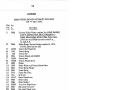
ACCESSORI ES
Ref.
Part
No.
1
No.
228886
2
3
228885
228883
350708
267197
12361
22+13
5
6
7
8
9
10
11
12
13
1-i
15
16
17
18
19
20
200113F
22&12
22+11
200270X
1203Lj2
1203L+3
Z25&98
228+76
L1I+0o
22555k
Z00157X
2750
Z672’2
135 x7 Y
Description
Drip Pan (Plastic) complete, Nos. 228883, 228885 and
five 350708
Drip Pan
Drip Pan Drain Jar
Drip Pan (Plastic) Screw Nail
Hook Saddle Oil Gauge
Machine Hinge Connection (2)
Knee Lifter Connection Lever Lifting Rod Roller Bracket
complete, Nos. 200270X, Z2Lii+ll and 224412
Set Screw
Rod Roller Bracket with 200113F
Rod Roller
Hinge Screw
Oiler (copper plated) with l203i3
Spout
Screw Driver
Screw Driver (Bobbin Case)
Machine Rest Pin (wood)
Wrench
Attachment Screw
Bobbin
Wrench (3/32 in. Hex.)
Needles, six, size 21 with Supplementary Shoulders
33
ACCSSORI ES
12
/14
13
15
18
‘F
16
1f
SING
1!
Li
1’
17
34
ACCESSORIES
BOBBIN WINDER (SWINGING AUTOMATIC, RIGHT HAND)
FOR “V” BELT DRIVE
Ref.
No.
Part
No.
1
259462
2
225462
3
4
5
6
7
8
9
10
11
12
13
14
15
16
17
18
19
20
21
22
23
24
25
26
27
28
201572X
13710
2102
225461
201499X
200082D
228026
259662
225456
225455
259930
457AL
200113F
259429
259428
200299X
202478
225458
225459
225444
200056E
225381
259660
225454
244071
225453
Description
Universal Bobbin Winder complete,Nos.200056E,200082D,
200113F, 200299X, 202478, 225381, 225444, 225453 to
225456, 225458, 225162, 228026, 259428, 259129, 259662,
Z59930,two each 225459 and wood screws 3/4 in.,
No. 12,RH.B.
Bobbin Winder Tension Bracket complete,Nos. 13710,
201572X, 225461 and two 2102
TensionStudThumbNut
Tension Spring
Tension Disc
Tension Bracket with 201499X
Tension Stud
Tension Bracket Screw
Washer
Bobbin Winder and Tension Bracket Base
Frame Spring Plunger
Frame Spring
Pulley with Li57AL
Set Screw
Brake Clamp Screw
Brake Clamp
Brake (leather)
Trip Lever Hinge Screw
Stop Latch Trip Lever
Stop Latch Thumb Lever
Stud
Stop Latch
Screw
Spindle
Oil Well Washer
Frame Hinge Pin
Oil Packing (wick)
Frame with 244071 and 259660
35
ACCESSORIES
BOBBIN WINDER (SWINGING AUTOMATIC, RIGHT HAND)
FOR “V’ BEL’r DRIVE
6
0
2{j
7
8
9
10
0
j/fl
12
26
13
24
14
15
16
21
17
18
19
36
ACCESSORI ES
KNEE LIFTER
Ref.
No.
Part
No.
1
ZZ890L
2
228751
3
228707
5
6
7
8
9
10
1].
12
13
14
15
228363
2003
f
1
7AL
228155
228367
228386
228752
228365
200530C
267 371i
350231C
228318
228364
Description
Knee Lifter Rock Lever 1
comp1ete,Nos.228318,22836
,
228365, Z28751 and Z67374
Bracket 228707 with 228363, 228367, 228386, 228L55 and
228752
Bracket with 200347AL and three wood screws 7/8 in.,
No. 12
Hinge Pin
Stop Stud Set Screw
Position Spring
Stop Stud
Spring
Rock Lever with two 350231C
Rod
Set Screw
Extension with 200530C
Set Screw
Knee Plate Arm
Knee Plate with 350231C
37
ACCESSORI ES
KNEE LIFTER
2
r
9
4
8
5
13
(‘12)
Cl
13
15
38
NUMERICAL
Page
No.
Part
No.
Z37D.
457AL.
691F...
1258AL
1266AL
1623X.
2102
•
.
16
34
18
24
24
20
34
32
12361
13710
.34
.30
40025
32
41400
120342
.32
120343
.32
.24
140 197AL
140434ALX. .26
14
141 566G.
.14
141567G.
Z00001E.
.28
200004E
16
28
200006E
30
200029C
22
200029E
200034C
30
Z00036E
22
Z00047D
16
200047X
16
Z00054C
22
200056E
34
Z00061ALX.. .28
200072G
14
Z00074F
18
200082D
34
200086ALX.. .18
28
200089X
200106E
22
ZOO11OD
28
ZOO113F... 18,32, 34
ZOO125ALX. ..14
200132E
18
200133E
16
200135G
28
200143X
ZO
200157X
32
20
Z00159F
Z00173D
22
200175D
14
200176E
30
-
•
.
Part
No.
LIST
Page
No.
OF
Part
No.
Z8
+202056
200262X
18
202090
200270X
32
202253
Z02254
200Z99X
34
202277
20
200309E
202330
200333C
14
202337
200337C
20
202338
200341C
14
200347ALX. .36
202399
202401
ZOO35ZALX. .18
Z0Z478
200355X
18
20255
2
200363ALX. .14
200374ALX...14,28 202625
200378C
14, 28 202671
203013
200382ALX. .24
200383G
14, ZZ 203214
200388G
14,28 203216
200398C
22, 30 203473
203474
200530C
36
203648
200580X
24
200582X
20, 24 204235
204271
Z00587D
30
204329
26
200591X
204925
26
200594E
206608
200653C
18
207072
Z00738X
18
208566
200948F
18
210949
200975F
18
223438
26
200984C
223655
20
201199F
223703
ZO1ZZOALX.. .24
223704
20
201224X
Z2370
6
26
201253F
223811
201254C
24
223812
201313F
16
223847
Z01341C
14
224411
20
20140ZX
201409F
224412
26
224413
34
201499X
Z01517E
30
225381
201518E
22
225444
201525E
225453
16
201537X
18
225454
201572X
20,34 225455
225456
201738X
20
201750X
20
225458
202005
ZZ5459
16
ZOO1SBD
PARTS
Page
No.
26
Part.
No.
Z25461
225462
18
14, 24 225498
22, 24 225554
30
225585
14
225837
227227
18
228026
18
228318
14
228363
18
34
228364
14
228365
228367
22
22838
18
6
228455
18
228476
26
228707
26
228751
26
228752
26
228883
26
228885
16
228886
20
228904
14
20
+235099
235100
18
18
235706
18
236060
18
240003
20
240004
22
240020
20
240023
20
240025
20
240039
240067
16
240068
16
24
240139
240223
32
240224
32
3Z
240245
240259
34
240564
34
241674
34
241675
34
241763
34
241765
34
34
243744
34
244048
Page
No.
34
34
32
32
28
22
18
34
36
36
36
36
36
36
36
32
36
36
36
32
32
32
36
Z6
26
14
20
16
16
14
20
18
14
18
18
14
22
22
Z4
22
18
26
26
24
20
22
20
39
NUMERICAL
Part
No.
244071
244084
+244701
+244702
244704
244705
244706
244707
Z44708
Z44709
244710
244711
244712
244713
244714
244715
244716
244717
244718
244719
244720
244721
244722
244725
244726
244727
244729
244730
244734
244735
244736
244737
244738
244739
244740
244741
244742
244743
244744
244745
244746
244747
244750
244751
244759
244760
Page
No.
Part
No.
14, 34 244761
28
244762
16
244763
244764
16
28
259428
16
259429
30
259462
ZZ
259660
22
259662
22
259990
22
263093
26
263554
24
264714
24
267031
24
267032
24
267033
30
267034
30
267053
24
Z67063
30
267139
28
267140
14
267152
14
+267158
30
267160
14
267161
20
267162
20
267166
22
267167
267172
20
20
267180
20
267182
20
267188
20
267190
20
267194
20
267197
20
267198
20
267200
20
267212
20
267215
20
267220
20
267221
14
+267222
18,32 267224
16
267229
24
267230
24
267231
Page
No.
24
24
24
24
34
34
34
34
34
34
24
28
14
22
22
24
22
28
24
28
28
16
14
14
14
14
28
28
28
24
24
24
24
28
32
28
28
28
28
16
14
14
14
30
30
30
LIST
OF
Part
No.
26723Z
267233
267236
267238
267239
267242
267245
267Z47
267248
267251
267254
267256
267257
267261
267262
267263
267265
267272
267273
267276
267277
+267284
+267285
267286
267287
267289
267293
267315
267316
267321
267322
267323
267351
+267355
267356
267358
267359
267360
267361
267362
267365
267366
267367
267368
267370
267371
PARTS
Page
N o.
30
30
14
18
14
32
24
14
28
18
30
30
30
30
30
30
18
16
22
30
28
30
30
30
30
18
30
20
20
30
30
20
18
26
26
26
26
28
28
30
28
28
28
20
28
28
Part
No.
267374
267388
267395
267396
267397
267398
267399
267400
267466
267623
268063
268064
268065
268066
268067
268197
270026
270653
270880
271017
272142
275049
275050
276061
350197E
350231C
350366X
350393C
350405C
350440X
350464X
350467C
350477C
350492C
350548C
350563E
350564E
350566C
350574F
350581C
350588X
350595XC
350708
Page
No.
.
.
.
36
16
16
16
16
16
16
16
14
24
ZZ
24
24
24
26
16
24
22
28
16
14
18
18
Z8
22
36
22
22
26
24
18
24
24
14
24
16
28
30
26
18
20
.28
3Z