1
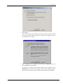
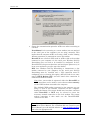
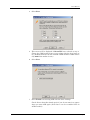
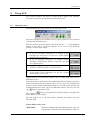
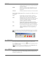
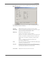
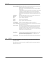
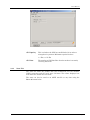
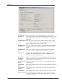
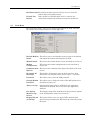
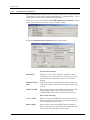
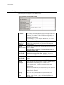
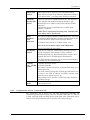
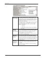
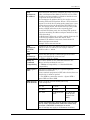
AirLink Communications Wireless ACE User’s Manual AirLink Communications, Inc. December 3, 2002 Information in this document is subject to change without notice. Copyright AirLink Communications, Inc, 1993-2002. All rights reserved. Please send comments to: email: [email protected] Fax: 510-226-4299 Phone: 510-226-4200 Post: AirLink Communications, Inc. Attention: Technical Publications Dept. 472 Kato Terrace Fremont, CA 94539 AirLink Tech Support can be reached at 510-226-4200 Mon-Fri 9:00a-5:00p Pacific Time. Copyright 2002 AirLink Communications, Inc. All Rights Reserved Table of Contents 1. Getting Started ............................................................................................... 1 1.1 Install ACE .................................................................................................... 1 1.2 Modem Configuration Wizard....................................................................... 2 2. Using ACE ........................................................................................................ 7 2.1 Minimized View............................................................................................. 7 2.2 Status Screen................................................................................................. 8 2.2.1 CDPD Tab ................................................................................................................ 8 2.2.2 GPS Tab.................................................................................................................. 10 2.2.3 Stats Tab ................................................................................................................ 11 2.3 Tools Menu .................................................................................................. 13 2.3.1 Communication Options........................................................................................ 14 2.4 Multiple Instances of ACE .......................................................................... 15 2.5 Modem Password......................................................................................... 17 2.6 Configuration Tabs...................................................................................... 17 2.6.1 Changing Modem Parameters .............................................................................. 19 2.6.2 Configuration Screen - CDPD Tab........................................................................ 20 2.6.3 Configuration Screen - Connection Tab ............................................................... 21 2.6.4 Configuration Screen - COM Port Tab ................................................................. 28 2.6.5 Configuration Screen - Security Tab .................................................................... 28 2.6.6 Configuration Screen - Modbus Tab ..................................................................... 29 2.6.7 Configuration Screen - PinPoint Tab ................................................................... 30 2.6.8 Configuration Screen - Monitor Tab..................................................................... 33 2.7 Templates .................................................................................................... 34 3. Troubleshooting............................................................................................ 36 4. More Information ......................................................................................... 44 Copyright 2002 AirLink Communications, Inc. All Rights Reserved Wireless ACE User’s Manual 1. Getting Started Wireless ACE (AirLink Configuration Executive) is a Microsoft Windowsbased tool for easily configuring your AirLink modem or checking the modem's status either locally or remotely. This manual explains the details of using ACE. AT commands (e.g. ATE1, ATDT..., etc.) are the usual method for configuring modems through a terminal emulation program (like HyperTerminal in Windows). AT commands however only work locally -- to a modem that is connected via a serial port. AirLink modems not only accept AT commands, but with Wireless ACE the AT commands (normally input by hand to a modem) can be set quickly and easily in a graphical, Windows environment. In addition, your AirLink modem can be configured over a serial port with ACE or remotely (when the modem is registered) -- in the field, accessing it over an Internet connection from your computer instead. ACE not only configures your modem but will display statuses from your modem either locally or remotely as well. So you will know if a modem is functioning properly, or in a bad location in the field, etc. Wireless ACE has two options to talk to the AirLink modem locally using Point to Point Protocol [PPP]: Direct PPP with the modem's own builtin PPP stack or a Windows Dial-Up Networking (or DUN) connection. To talk remotely to a modem, a DUN connection usually is not necessary. See section 1.2 for details. NOTE: This manual does not explain initial setup and configuration of an AirLink modem. Please see your modem User's Manual for step-bystep instructions. Also this manual assumes you have an understanding of TCP/IP networking. 1.1 Install ACE Before installing ACE be sure your system meet the following requirements: System Requirements for Wireless ACE AirLink Communications, Inc. • Windows 98/ME, NT 4.0, 2000 or XP computer. • optional Dial-Up Networking (DUN) installed and configured. December 3, 2002 Page 1 Wireless ACE For information on a Windows DUN connection, please refer to the appropriate modem User's Manual, or go to http://www.airlink.com/help for step-by-step instructions for the version of Windows you are using. • For remote connections: an ISP for connections to remote modems (via your LAN gateway). And ensure that: a. Your LAN IP is not in the range of 10.x.x.x. b. Your network does not block UDP ports 17300-17400. Install ACE 1. Insert the "Modem Utilities" disk. 2. Go to Start→ →Run. 3. Type in A:\acesetup and select OK. 4. You'll be prompted for the default directory C:\ACE, hit Enter and this installs Wireless ACE to C:\ACE on your hard drive. Note: If you downloaded ACE from the AirLink website, it will be in the form of a .ZIP file. Create a folder for ACE (such as C:\ACE) and extract the contents to it. (You can download the latest version of ACE from http://www.airlink.com/ace.) 5. Start Wireless ACE by double-clicking on ace.exe (or creating a shortcut for it and double-clicking the shortcut). 6. Go to the next section to initially setup Wireless ACE... 1.2 Modem Configuration Wizard When Wireless ACE first starts, the Modem Configuration Wizard will popup. If the wizard does not come up on start, you can set the communication options by... • selecting the • selecting Tools→ →Communication Options. button and then The first screen that comes up in the Modem Configuration Wizard is as follows: Page 2 AirLink Communications, Inc. User’s Manual 1. Select Next. If you do not want this wizard to come up each time you start ACE, check "Never show this wizard again" and then select Next. (It can be re-enabled later in ACE.) 2. For a connection to a modem over the serial or COM port of a PC, select Local and select Next. To connect to a modem not connected locally to the computer, select Remote/IP and enter the IP address. (The remote modem must be turned on and registered on the CDPD network.) Then select Next. AirLink Communications, Inc. December 3, 2002 Page 3 Wireless ACE 3. Choose the communication option for ACE to use when connecting to a modem. None/Manual is for connecting to a remote modem (one not attached to the serial port of the computer you are using currently). This implies that the computer ACE is on is using a LAN, or other existing Internet connection, to communicate over to the modem. DirectPPP uses a built-in PPP stack in ACE to talk to the modem connected to your computer via the serial port. Windows Dial-Up Networking does not need to be installed or configured. In fact, DirectPPP will also present baud rate and serial port options to try to locate your modem for you. (See step 5 for details.) DUN uses Windows Dial-Up Networking to communicate to the modem connected to your computer via the serial port. Dial-Up Networking must be installed and a PPP connection must be configured prior to selecting this option. ACE will look for an entry named CDPD Modem PPP and will launch this connection to communicate with the modem. Note: Once your modem is registered, either the DirectPPP or DUN connections can be used to access other modems remotely via the CDPD modem connected to the computer. The AirLink CDPD modem (connected to the computer you are using) is used as the Internet connection for the computer. Setting the Remote IP at step 2 should have been done, and then either DirectPPP or DUN may be selected to create the necessary network connection to the local modem. The remote modem connection is then made over the DirectPPP/DUN connection via ACE. Note: To setup a Windows DUN (PPP) connection, please refer to your modem User's Manual. For a Windows OS not covered in your User's Manual, go to the AirLink website at www.airlink.com/help and select the appropriate OS. Page 4 AirLink Communications, Inc. User’s Manual 4. Select Next. 5. This screen will be displayed if DirectPPP was selected at step 3. Choose the COM (serial) ports to scan, along with the baud rates to try. (Default baud rate on new AirLink CDPD modems is 9600. Select only 9600 if the modem is new.) 6. Select Next. 7. Select Finish to start using ACE with the above settings. Check "Never show this wizard again" if you do not want it to appear when you start ACE again. (Note that is can be re-enabled later in ACE if needed.) AirLink Communications, Inc. December 3, 2002 Page 5 Wireless ACE If you need to configure your modem for the first time, please refer to your modem User's Manual. Page 6 AirLink Communications, Inc. User’s Manual 2. Using ACE This section describes the basics of using ACE to display and configure parameters and gives an introduction to what they mean. 2.1 Minimized View When ACE first starts up you will see the following screen: The title bar displays the IP address of the current modem you are connected to along with the modem type. The first button on the far right of the ACE title bar ( _ ) is the Minimize button. If you click it, ACE will minimize as an icon on your Windows Taskbar, near the time display. • If you are currently connected to a modem locally (through your serial port), you will see a yellow modem showing you’re connected. • If you are currently connected to a modem remotely (through a LAN/existing Internet connection), you will see a lightning bolt. • If ACE is in idle/sleep mode you will see Z-Z-Z. • If the modem is not responding, you will see a yellow modem with a red X over it. Double-click the icon near the system clock to bring ACE back into its Minimized screen. The next button (a small square) is the Maximize button. Clicking it will open ACE to the Status Screen by default. (Note: If you were in the Configuration Screen in ACE, and hit the Minimized button, you would be put back into the Configuration Screen when you hit the Maximize button.) You may also use the button to maximize ACE. button will immediately poll the modem and update the The refresh or lights, RSSI, etc. that display. The last button [X] is the Exit button. Clicking this button will close Wireless ACE. Status fields in this view: RSSI (dBm) AirLink Communications, Inc. The Received Signal Strength Indicator: from -60 to -94 is good signal, measured in decibels/milliwatt. (dbm) A December 3, 2002 Page 7 Wireless ACE stronger signal is closer to zero, since this is measured in negative numbers. BLER Shows the current percentage of Block Errors on the Receive channel. This number should be low for best performance. Channel CDPD network channel currently in use by the modem. Status lights on this screen: (These correspond to the LEDs on the face of the modem.) Chan Channel light. Green if the modem is locked on a channel. Red if the modem cannot acquire a channel. Link Link light. Green if the modem has established a CDPD link. Red if the modem has not. This is the data layer protocol of CDPD, assigning you with a TEI (Temporary Equipment Identifier). Reg Registered light. Green if the modem is currently registered to a CDPD network. This means encryption keys have been passed, and you are now assigned an IP on the Internet. Red if the modem is not registered. GPS Applies to Pinpoints or RCM ONLY. The modem has acquired a fix with three or more Geopositioning satellites. Note: If you don’t have see Chan, Link and Reg lights in green, your modem will not be accessed remotely. If the modem is not responding, you'll see the following: 2.2 Status Screen This section describes the Status menu and what the readouts mean. To view Status information, click on the status window by default. button. This brings you to the (Note: You can also easily go to the Tools menu or the Configuration tabs once ACE has been expanded from the Minimized view.) 2.2.1 CDPD Tab The CDPD tab is the first tab displayed when viewing the modem status. It shows the stats of the modem on the CDPD network, if its registered or not, the side it is currently on, etc. Page 8 AirLink Communications, Inc. User’s Manual The CDPD stats can also be saved to an ASCII text file at any time using the Save As button below. The Minimize button will change the view in ACE to the Minimized Screen view of ACE (see Section 2.1 for more). Channel CDPD network channel currently in use by the modem. RSSI (dBm) The Received Signal Strength Indicator: from -60 to -94 is good signal, measured in decibels/milliwatt. (dbm). RRM State Radio Resource Management state: Acquired - the modem has acquired a channel Wide Scan - the modem is conducting a wide area channel scan. Ref Scan - the modem is conducting a reference channel scan. Quality Check - the modem is conducting a channel quality check. Inactive - a temporary state where the modem is not performing any RRM function. Link shows if the modem has established a CDPD link (TEI assigned and link layer established) or not. Network Displays if the modem is registered on the CDPD network. If the modem is not registered, an error message will be displayed explaining what registration error had occurred. Color Codes Displays the current area and cell color codes. AirLink Communications, Inc. December 3, 2002 Page 9 Wireless ACE Receive BLER The BLock Error Rate on the forward channel, measured over BLER average time for 282 blocks of data. (Blocks Sent - Correctable Blocks Received) / Total # of Blocks Sent * 100% A Reed-Solomon code block consists of 63 symbols, each of 6 bits in length. 47 symbols [282 bits] are data, the remaining 16 symbols [96 bits] form the forward error correcting code. The forward error correcting code is used to determine good vs. bad blocks. Transmit BLER The BLock Error Rate on the reverse channel, measured over the average time for 250 blocks of data. SPI Service Provider Identifier. WASI Wide Area Scan Identifier. SPNI Service Provider Network Identifier. Cell Number CDPD cell number that the modem is currently in. Power Product This is used by the CDPD network to compensate for transmit and receive power levels 2.2.2 Power Level The modem's current CDPD transmit power level. This power level is derived from the Power Product transmitted over the network from the Cell tower and the current received signal strength value at the modem. Values are 0 to 10 where 0 is the highest power level (600 milliwatts). Host Mode Displays what Startup Mode Default the modem is set to. For example, AT command mode by default, or UDP mode, etc. (See section 2.6.3 for configuration.) Last Contact The last time that ACE had polled the modem for information. GPS Tab The GPS tab shows the status and quality of the GPS fix if the modem is a PinPoint or RCM. The GPS stats can also be saved to an ASCII text file at any time using the Save As button below. Page 10 AirLink Communications, Inc. User’s Manual GPS Quality This is whether the GPS has established a fix in order to triangulate its position. Minimum required is three. 1 = Fix, 0 = No Fix GPS Sats 2.2.3 The number of GPS Satellites that the modem is currently receiving data from. Stats Tab The stats tab shows the packets and bytes transferred over the modem's CDPD connection and the serial port, and more. The values displayed are from when the modem was last reset. The stats can also be saved to an ASCII text file at any time using the Save As button below. AirLink Communications, Inc. December 3, 2002 Page 11 Wireless ACE CDPD Packets This is the number of incoming data packets to the CDPD Received modem since the last reset. The modem must be in data, not AT Command mode for this to be valid. ACE traffic is included in this count. CDPD Packets This is how many packets the modem sends out to the CDPD Sent network since the last reset. The modem must in data mode, as above. ACE traffic is included in this count. CDPD Bytes Received This is a count of the number of incoming bytes (over CDPD) to the modem since the last reset. ACE traffic is included in this count. CDPD Bytes Sent This is the number of bytes the modem sent out over CDPD since the last reset. ACE traffic is included in this count. Host Mode Displays what Startup Mode Default the modem is set to. For example, AT command mode by default, or UDP mode, etc. (See section 2.6.3 for configuration.) Outbound Rejected Packets This is the number of packets transmitted by the modem to the CDPD network and then rejected by the network. The primary cause of this is wrong source IP. Serial Receive This is the number of bytes received over the RS-232 serial port Bytes of the modem. Serial Sent Bytes This is the number of bytes sent out to the RS-232 serial port of the modem. TX Channel Busy % This is an indicator (in percentage format) of how busy the TX channel is. TX Channel This displays the number of time the modem tried to send data Busy Attempts and the TX channel was busy. This is reset every time you query this parameter and only shows the number of attempts since the last query. Page 12 AirLink Communications, Inc. User’s Manual Bad Passwords The number of times someone tried to access or reset the modem with an invalid password. Friends List Rejects 2.3 If the modem is in Friends mode, this is a count of any connections attempted by modems or hosts not on that list. Tools Menu The Tools menu allows you to access many of the features in ACE. Note that the shortcut keys to these features is on the right side. Refresh Modem This allows you to send another status request to the modem Status and update the modem data displayed in ACE. Modem Status This selects the modem status screen, described in section 2.2 Modem Configuration This selects the modem configuration screen, described in section 2.6. Communication This selects the communication options described in the next Options section. Re-enable All Warnings This enables all warnings, some of which may have been disabled by selecting the "Don’t ask me again…" check box. Password This allows you to enter the ACE password. Change Modem This allows you to change the value of the ACE password, as Password described in section 2.5. Always on Top Selecting this option ensures ACE will be the uppermost window on the desktop, above any other open application windows. Use Option Menus in Cfg Screen This displays drop-down mentions describe parameter options in the Configuration menu. See section 2.6. Display Wizard on Startup This option allows you to set up the ACE communication options using a wizard when ACE starts up rather than using the menu. AirLink Communications, Inc. December 3, 2002 Page 13 Wireless ACE 2.3.1 Communication Options The Communication Options menu in ACE allows you to select between connecting to a local modem (via the serial port) or a remote modem -- via an existing LAN connection or registered CDPD modem. Here, we are only concerned with Tools→ →Communication Options, shown below. This is how we will select a local or remote modem. Selecting Communications Options brings up this menu: Connection Settings: Modem IP This may be set to Local (serial) to establish a direct connection over a serial cable, or you may type in an IP (or select from the drop down list) to access a remote modem. Method: Direct PPP ACE will attempt to establish a Direct PPP connection to the host using an internal PPP stack provided by the modem. Windows DUN Choose this to connect to a modem using Windows DialUp networking. If the DUN connection is named “CDPD Modem PPP” it will be started automatically. Direct PPP Settings: Page 14 Com1 –Com4 These are the ports ACE will scan to attempt a Direct PPP connection. Note that other ports may be selected on the drop down list at Com4. 9600 - 38400 These are the baud rates ACE will scan to attempt a Direct PPP connection. Note that other baud rates may be selected on the drop down list at "4800." AirLink Communications, Inc. User’s Manual Status Timers: Status Update Interval (secs) When modem has acquired a channel ACE will request status updates with an interval of this many seconds between them. No Channel Status Update Interval (secs) ACE requests status updates at this interval when no channel has been acquired. Stop Updating after x Mins of Idle Time ACE stops requesting status updates from the modem after a specified amount of idle time (e.g. no longer writing settings, refreshing status, changing the modem, etc.) when this is checked. When updating stops, Wireless ACE displays a modem icon with Z-Z-Z over it. Configuration Timers: Command Response Timeout (secs) ACE will wait for this duration before it will consider the command to have timed out from the modem. Max Parameter Retries Maximum number of attempts before ACE attempts to write a parameter to the modem. Note: You may see the following screen if you attempt a Direct PPP connection to a remote modem: This informs you that the Direct PPP will access the Internet, and that this may block any other PPP or serial connections while you are using ACE. 2.4 Multiple Instances of ACE Multiple instances of ACE can be run on a single computer. This feature is used to view multiple remote modems simultaneously. Note: This does not work for multiple local ACE connections (e.g. two AirLink modems on two separate COM ports). This is because ACE looks for the entry AirLink Communications, Inc. December 3, 2002 Page 15 Wireless ACE "CDPD Modem PPP" in DUN and only one instance of that DUN connection may be running at any time. To start another copy of ACE: 1. Double-click the ACE icon again, or select the icon from the Start menu again. 2. Another copy of ACE will appear (usually over the position of the existing minimized window position of ACE -- move the window to a different position, if you desire). 3. Expand ACE and go to Tools→ →Communication Options. 4. Enter the new IP address, in the "Modem IP" field, of the modem you want to view with that instance of ACE. You can also use a local, DUN/PPP connection to an AirLink modem on your serial port and view multiple remote modems simultaneously using the Internet connection to the local modem. To do this: 1. Start the first instance of ACE -- the copy that starts the DUN by default. (If it is not set to start DUN, continue anyway and by step 4 DUN should start.) 2. Expand ACE and go to Tools→ →Communication Options. 3. Set "Modem IP" to Local (Serial). 4. Set "Method" to Windows DUN. 5. Select OK. 6. DUN should now startup, or continue to remain connected to your local modem. 7. Start the next copy of ACE by double-clicking the ACE icon again, or select the icon from the Start menu again. 8. If you get an error since your PPP connection is already running, select Ignore. 9. Go to Tools→ →Communication Options in the second copy of ACE. 10. Enter the IP address in the "Modem IP" field. 11. Ensure the "Method" is set to either Windows DUN or None (Remote). 12. Select OK and you should start seeing the remote modem from over your existing PPP connection. 13. Repeat steps 7-12 to start more copies of ACE. Limitations of running multiple copies of ACE: Page 16 • Only one instance can be set to "Local" mode (i.e. running DUN/PPP). • Settings are written to the config. file (C:\Windows\ace.ini or C:\Winnt\ace.ini) periodically. ACE only reads the settings when it starts, but it writes settings periodically, including when it shuts AirLink Communications, Inc. User’s Manual down. So if some options are changed in one copy of ACE and then it shut down (e.g., Communication Options, window positions, etc.), those settings will be overwritten when the second instance of ACE is shut down. Note: Windows 9x/ME does not handle multiple copies of ACE well, regardless of what kind of system it is. Windows 2000/XP or NT 4.0 is highly recommended to reliably run multiple copies of ACE. 2.5 Modem Password Each AirLink modem has a password which is necessary to change modem parameters. Each time a parameter or parameters are changed, and Write to Modem is selected, a prompt for the modem password is displayed. The default password is 12345 for each AirLink modem. It is highly recommended you change the modem password. To change the password do the following: 1. Select Tools→ →Change Modem Password. 2. Enter the old modem password, and the new modem password twice. Note: The limit of the password length is 8 characters. 3. Select OK to accept the change to the modem password. If the password is ever forgotten, you may call AirLink Tech Support for assistance at 510-226-4200. Please provide your modem IP, EID, Company Name, and your name. (Note: This modem password is different from the AT command password for configuring the modem. Please consult the AirLink CDPD User's Manual for more info.) 2.6 Configuration Tabs This section describes how to display modem configuration parameters and change modem configurations. Note: To get detailed information on any of the parameters under the tabs in the Configuration screen, please consult the AirLink CDPD User's Manual for more info. AirLink Communications, Inc. December 3, 2002 Page 17 Wireless ACE button at the These screens can be accessed by pushing the bottom of the status screen or selecting Tools→ →Modem Configuration from the top menu. Note: Some parameters and tabs that are listed in this manual will only show up in ACE with the appropriate modem and firmware version combination. Any parameter or tab like this will list what modem and firmware version is required. A example Configuration screen is shown below: The title bar displays the IP address of the current modem you are connected to. The Minimize button will change the view in ACE to the Minimized Screen view of ACE. See the Minimized Screen section for more information. (Also, possibly depending on software version, the title bar may show modem type like Raven or PinPoint). The "Parameter Name" field under each tab includes the AT command value in brackets on the left, and the parameter field name on the right. Current Template Template file in use, if any. See section 2.7 for more. Equipment ID The unique equipment identifier of the modem. Page 18 SW Revision The version of firmware loaded in the modem. HW Revision Revision code for NRM CDPD modem module. AirLink Communications, Inc. User’s Manual Config Tabs Note that Tabs will change depending on the modem type, e.g. Raven or Pinpoint or others. Common ones are: CDPD, Connection, COM Port and Friends. Pinpoints will have a Pinpoint Tab and Ravens will have a Modbus Tab. Changing Parameter Value To update a parameter in the modem, double-click on the New Value column for that parameter. Enter the new value, and hit your Enter button. Click on Write to Modem to save the parameter change. Write to Save your parameter changes to the modem firmware. This Modem button ensures you changes will remain if the modem is powered off or reset. Reset Modem button Resets modem, causes it to restart, and go back onto the CDPD Network. Copy All button Copies all the data from the Current Value fields and pastes them into the corresponding New Value fields. Clear New button Clears all the New Value fields. Status button Open the Modem Status Screen. Refresh button Retrieve the most recent modem parameters. 2.6.1 Changing Modem Parameters To change one of the parameter values under a Configuration Screen tab do the following: 1. Select the new value from the New Value field from the drop-down menu. Or double-click the New Value field corresponding to the parameter you want to change. 2. When the new value is selected or entered, hit the ESC key to finish. 3. Select the Write to Modem button to save your new settings to the modem. 4. If prompted for a modem password to write to the modem, enter the password now and select OK. 5. If you are prompted to reset your modem, select Yes or else the parameters will not take effect. To switch from the drop-down menus in the New Value fields to using a blank field for manually inserting the values, uncheck Tools→ →Use Option Menus in Cfg Screen. To enter the same values for multiple modems see section 2.7 for use of templates. AirLink Communications, Inc. December 3, 2002 Page 19 Wireless ACE 2.6.2 Configuration Screen - CDPD Tab The following tab primarily pertains to CDPD network information (including the IP assigned to the modem itself). [\N] Side Preference This setting determines which CDPD service provider you use in your area (A or B). Your CDPD service provider should tell you how to set this.. Roaming charges may be incurred if it's incorrect. Valid settings: 1 = A side only, 2 = B side only, 3 = A side preferred, 4 = B side preferred. [S110] Device IP Address This modem's IP address. Example: 192.100.100.100. NOTE: Only change this if you get a new IP from your CDPD provider. [S110] Device Port Modem port for incoming TCP and UDP requests. Possible value: 0 - 65535. Must match port number of remote modem you are communicating with. [S116] Service ID Preference 0-Only Use, 1-Prefer Use, 2-Don't Use, 3-Don't Care Determines usage of the S111 register. Default is 3. Note: to be set by those expert in CDPD only. [S111] Service ID SPI/SPNI/WASI where 0=Don't Care, 1..65535=Valid Values Note: to be set by those expert with CDPD only. [S112] Channel List Mode Holist: A range of highest signal strength CDPD channels in the immediate surrounding area. Default is "2." 0 = No Channel List, 1 = Fixed Channel List, 2 = Hot Channel List. Note: Fixed Channel List is NOT recommended in normal situations. It may cause the modem to go offline if the channels in the list fail. [S113] Channel List Page 20 This is the list of nearby CDPD channels the modem searches on which the modem searches for service. Format: chan1, chan2, ... (up to 32 channels). Enter 0 to clear the list. AirLink Communications, Inc. User’s Manual [3W] 3 Watt Booster Enable support for a separate piece of hardware which boosts signal strength on the antenna. (Optional hardware.) 0 = No power boost, 1 = 3 Watt power booster is attached [*DSIDE] Disable switch back to CDPD preferred side. The modem, if Disable Side on the opposite side preference than it should be, will Switch automatically try to switch to the correct side For CDPD preference. Valid settings are: 0 = Periodically try to switch back (default); 1 = Disable NOTE: This is an advanced setting, only switches side when side is set to "Preferred." [HYS] Minimum RSSI Hysterisis This setting configures Minimum RSSI Hysterisis. This sets the minimum RSSI difference between channels that would cause the modem to switch to the stronger channel. 0 = Default, which sets it to ‘3’. Other values: 3-16 Note: To be set by those expert with CDPD only. [Raven II and PinPoint 9612 Only.] [#X] Debug Output When set to 1 (enabled), modem debug messages are sent over the serial port of the modem. Using a terminal emulation program (e.g. HyperTerminal) the output can be captured and sent to AirLink support for diagnosis. Note: This option is ignored if you are not communicating to the modem via AT command mode. [*CTSE] 1 = Enable assertion of CTS CTS CDPD 0 = Disable [default] Enable This feature asserts CTS (Clear To Send) when there is no CDPD connection. Note: Flow control (AT\Q) will override this indication, so if you want to use CTS to indicate no CDPD coverage, flow control has to be off (AT\Q set to 0). RS232 voltage levels: Positive = CDPD coverage, Negative = no CDPD coverage. [#ZZ] Sleep Not available. Must be ZERO. If set for 2 or any other Mode value, change it to 0. 2.6.3 Configuration Screen - Connection Tab The Connection tab is where you will find parameters controlling the connection (via network or serial port), like timeouts and DTR, etc. This tab is used with both UDP and TCP modes (along with other connection types), and not all of the parameters will be used for each connection type. AirLink Communications, Inc. December 3, 2002 Page 21 Wireless ACE [S0] TCP Auto This register determines how a modem responds to an Answer Mode incoming TCP connection request. The modem remains in AT Command mode until a connection request is received. DTR must be asserted or Ignore DTR must be set for a successful TCP connection The modem will send a “RING” string to the host and will assert DSR and DCD. A “CONNECT” sent to the host indicates acknowledgement of the connection [ACK]. Values: 0 = Disabled 1 = Enabled 2 = Telnet Server (Raven, Raven II and PinPoint 9612 Only). [S7] TCP The TCP Establishment Timeout determines the length of Establishtime the initiating modem will wait for a TCP connection ment Timeout request to succeed. If there is no response to the TCP connection request, the modem will issue a “NO_ANSWER” message to the host when the timeout occurs. Value is [0..255] seconds . Page 22 [S50] Data Forward-ing Timeout When in either the UDP or TCP data mode, when the pause between characters exceeds the Data Forwarding Timeout, the data being received on the serial port will be packetized and sent out to the CDPD Network. The value is programmable from 0.1 to 25.5 seconds in 1/10th of a second increments. [S51] Data Forward-ing Character This character causes the modem to packetize the data received on the serial port immediately and send it out over CDPD. This field contains the ASCII value of data forwarding character (0 = None). AirLink Communications, Inc. User’s Manual [S53] Destination IP Address When using the ATD (Dial) command, this entry is used to define a destination Data Mode (T for TCP or P for UDP), IP address and port number to default to should the user not provide one in the dial string . The Destination IP Address/Port is also used to screen incoming TCP and UDP packets. When a TCP connection request is received, the incoming packet must have a port number that matches the Destination TCP/UDP Port in S53. If it doesn’t match, the modem will reject the packet causing a BUSY indication to the requesting host. For normal UDP data mode, the incoming UDP packets must have matching IP address and port numbers or they will be discarded. For Half-Open UDP mode, set AIP=1 which allows any IP in, but the port number must still match. If the Destination IP Address is non-zero, then both the IP address and port must match. Example Value: 192.100.100.100 [S53] Destination TCP/UDP Port Destination IP Port. This MUST match the port of the modem or device to which you are trying to connect. Possible value: 0 - 65535 [S53] If User does not specify a connection type in the ATD Destination string it will default the value set here. Connect Mode T = TCP P = UDP N = Telnet. [S210] AT This causes modem to use commands similar to the Command "Hayes" wireline modems if set to "1". Compatibility 0 = NRM6812 Compatibility 1 = Standard Modem Compatibility. [S211] Ignore DTR DTR [Data Terminal Ready] is a required signal for creation of a connection. If your terminal equipment (ie RTU other device) does not provide this, it must be ignored. 0 = Use DTR for connection control 1 = Ignore DTR 3Ignore DTR and Force DSR. [MD] Startup Mode Default Mode to startup in when modem powers up. Valid settings are: 0 = AT 3 = UDP 1 = SLIP 4 = TCP 2 = PPP 5 = Hybrid UDP -TCP 15 = Raw (for build-specific versions like MDT) NOTE: Anything other than '0' means you won't be able to enter AT commands, and some values may not allow a DUN/PPP connection to work. (Not all settings may apply to all firmware revisions.) AirLink Communications, Inc. December 3, 2002 Page 23 Wireless ACE [MD] UDP Mode Default This mode configures the various parameters associated with the different modes of UDP. NOTE: All options (except '0') are only used when Startup Mode Default is set to 3 (UDP). 0 = Normal 3 = BSAP 7 = Reliable UDP 1 = Modbus ASCII Hex ID 6 = Modbus Variable RTU 8 = Multicast UDP 2 = RTU (Bin ID) [Option 6 requires you to set the parameters MVOFF, MVTYP, MVLEN, and MVOPT. Only valid in Raven modem versions 199902A or later] [S60] Telnet Echo Mode (Raven/Raven II/PinPoint 9612 Only) In Telnet terminal emulation mode, this S register determines how characters are echoed, either locally, remotely or with no echo. 0 = No Echo; 1 = Local Echo; 2 = Remote Echo NOTE: When set to “remote echo”, the echoing of characters is up to the host telnet application that you are connected to—it’s possible that the application may correctly not echo characters. [S82] UDP Half Open Mode When the modem is configured to operate in the half-open mode, when not in UDP data mode, it will accept AT commands from the serial port. If the AIP is set to 1, the modem can accept UDP packets from any source. Once it receives a packet, it locks onto that source and automatically goes into the regular UDP mode. It stays in that mode until either the DTR is dropped, the escape sequence is sent or the Half-Open timeout expires (after data is idle). The timer restarts every time a packet is received or sent. Once the modem exits active UDP, it returns to the Half-Open mode. If the destination address is set to a nonzero value, everything will work the same as the above except that it will only accept UDP packets from that specific destination and reject the rest. 0 = Normal; 2 = Half Open [S83] UDP Half Open Timeout Duration in seconds that modem will lockout all other connections after the current session goes idle. [AIP] Allow Any UDP IP 1 = Allow any incoming IP to connect in default UDP mode; respond back to the IP that sent you UDP packets. [range of 0..255] where NN is the number of seconds or 0 = Forever. NOTE: Still subject to any Friends filters that may be defined. Page 24 AirLink Communications, Inc. User’s Manual [HOR] UDP Half Open Response Sets whether or not to issue a RING CONNECT response for UDP Half Open mode. Note: Quiet Mode must be off. 0 = no response issued. [default] 1 = issues a RING CONNECT [S220] Break On TCP Connect When a TCP connection is made, the modem transmits a break signal specified of the duration specified by this register. Break length in 0.1 seconds [S221] Delay Connect Response Seconds to delay CONNECT response after TCP connection is made. (Also used for RKEY) [E] Command Echo The Local Echo command controls if the modem "echoes" the characters sent to it back to the host. For some applications, local echo is not required as the host does not need to confirm what has been sent to the modem. For terminal emulation, local echo can be used to verify what has been sent to the modem with each keystroke displayed on the terminal. 1 = Echo on; 0 = Echo off. [V] Command Response Mode This mode is used to define how the modem responds when commands are sent to it. Responses can be either plain text messages (Verbose) or a single numeric digit (Terse). Numeric control is better suited for machine applications while plain text is more easily understood by the user. 0 = Terse (numeric) command responses; 1 = Verbose command responses. [Q] Quiet Mode This turns off the result codes normally returned to the modem port on completion of commands. 0 = Output result codes; 1 = Don't output result codes. [X] Call Progress Result Mode This command exists for wireline compatibility. Adds “19200” to the “CONNECT” message, if S210 (wireline compatibility) is set to 1. Otherwise, this command does nothing. 0 = Turn off result codes; other value = Adds 19200 to CONNECT message if S210=1 [TCPT] TCP Inactive Timeout In the event that one side of a TCP connection aborts without a proper termination sequence, this timer register [TCPT] will cause the session to be dropped after a predetermined idle period. A default setting of one minute is recommended. N=1..255 minutes [seconds if TCPS is set]; 0=No timeout [Not Advised]. NOTE: Also see TCPS. AirLink Communications, Inc. December 3, 2002 Page 25 Wireless ACE [TCPS] Specify TCPT in Seconds This setting allows TCPT to be set in a more precise interval of seconds, or in minute [default]. Set TCP timeout units. 1 = TCPT units are seconds. 0 = TCPT units are minutes [default] NOTE: Also see TCPT [TCPX] Allow TCP Suspension This allows a TCP session to be suspended. Usually, dropping DTR disconnects TCP. When TCPX=1, dropping DTR suspends TCP, allowing you to use AT commands. When TCP is suspended, Raising DTR will resume the connection, or ATH may be used to drop it. 0 = No Suspension; 1 = Suspend TCP on No DTR [*DATZ] Disable Reset on ATZ Disable ATZ from the AT command interface. When ATZ is disabled, you'll just get back an OK when you type ATZ. This command is mainly meant to be used with legacy devices that insist on sending frequent ATZ commands (which take a long time for a CDPD modem to recover from) to the modem. 1 = Disable Reset on ATZ. 0 = Normal Reset (recommended). NOTE: This is an advanced feature. [*ENQ] Enable ENQ on TCP Connect Outputs an ENQ [0x05] after the TCP CONNECT delayed by the Delay Connect Response time [S221]. This is an advanced option [PinPoint 9612, Raven SM or Raven II modem - Raven Firmware 200105C or later.] [DAE] Disable This command is to safeguard against the possibility that AT Esc an escape character in the data might accidentally affect Sequence the modem. 1 = Disable AT escape sequence detection (recommended). [RKEY] Radio 1 = Enable MDS Radio Transceiver Keying (using CTS) Transceiver 0 = Disable (default) Keying [RTSI] RTS Input Mode Input Sensing on RTS Pin, used for monitoring external events. 1 = Enable RTS Input 0 = Disable [default] [PinPoint Only - Firmware 200110D or later.] [DTRI] DTR Input Mode Input Sensing on DTR Pin, used for monitoring external events. 1 = Enable DTR Input 0 = Disable [default] [PinPoint Only - Firmware 200110D or later.] Page 26 AirLink Communications, Inc. User’s Manual [IPL] IP List Dial Allows access to Modbus IP list via 1st 2 digits of dial string. Example: If IPL=1, ATDT1234567 will use "12" as the index to IP address in the Modbus list. [Raven SM or Raven II Only - Firmware 200104B or later.] [*DU] Dial UDP Always Dial UDP Always – Allows you to use ATDT and still go into UDP data mode 0 = Dial a normal TCP connection [default] 1 = Dial UDP, even when using ATDT NOTE: When this parameter is set a TCP connection cannot be dialed. [PinPoint 9612 and Raven II Only - Firmware 200110C or later.] [*USD] UDP Serial Delay UDP Serial Delay – Controls the delay [in 1/10 second increments] before sending the next UDP packet to the serial port Valid values are from 0 – 255 [0ms to 25.5 sec]. 0=Default. [PinPoint 9612 and Raven II Only - Firmware 200201D or later.] [*UDE] UDP This parameter enables sending UDP Debug messages to Debug Enable the IP specified by [*UDIP] 1 – Enable 0 – Disable [default] [PinPoint 9612 and Raven II Only – Raven II Firmware 200210C or later.] [*UDIP] UDP Debug IP This is the IP to which UDP debug messages are sent. *UDE must be enabled for debug packets to be sent to this address Format: AT*UDIP=166.1.2.3 [PinPoint 9612 and Raven II Only – Raven II Firmware 200210C or later.] AirLink Communications, Inc. December 3, 2002 Page 27 Wireless ACE 2.6.4 Configuration Screen - COM Port Tab This Tab shows the required parameters for setting the RS232 Serial port on the modem [\Q] Flow Control This register determines whether a modem sends flow control signals over the serial port. 0 = Disabled 1 = Transparent Flow Control [Xon-Xoff] 2 = Hardware [RTS/CTS] flow control. [S23] Baud rate This parameter sets how many bits per second the modem at which the modem will communicate. Possible Values are 1200, 2400, 4800, 9600, 19200, 38400. Note: 38400 is only available with the latest AirLink Windows modem driver and firmware after 200105 in the Raven II and SM modems. [S23] Data Bits This sets the number of data bits in a byte sent or received by the modem. Possible Values 7,8. Must be 8 for a PPP connection. [S23] Parity This register sets the parity the modem uses during error correction. Possible Values E = Even, O = Odd, M = Mark, N = None. N is the most common default. [S23] Stop Bits Change the stop bits on the serial port connection to either 1 (default) or 2. Note that 1 is required for a PPP connection. [PinPoint 9612 and Raven II Only - Firmware 200110C or later.] 2.6.5 Configuration Screen - Security Tab The Security Tab allows you to change settings which allow or block other modems or IP Addresses on the Internet or LAN. Page 28 AirLink Communications, Inc. User’s Manual [OPRG] Over Air Prog Enable Over-the-Air (via CDPD) programming of the firmware into the modem. This is approximately 300k of data, and will affect billing on a limited plan. 0 =Disable 1 = Enable [PinPoint 9612 Only.] 2.6.6 [FM] Friends Mode 0 = Allow any IP to Connect; 1 = Allow only IP's specified in Friends list to connect. [F0 - F9] Friends List IP's 0 -9 If a '1' is specified in Friends Mode, these are the only IP's which can connect. Note: This will also lock out ACE. A '255' may be used to open all the IP's in the range. Configuration Screen - Modbus Tab The Modbus Tab is ONLY used in the Raven series and it stores the parameters the Raven uses when emulating Modbus type communications or other Single Host to Multiple Client configurations. It is UDP ONLY. RTU to IP Address Mapping 1 - 60 AirLink Communications, Inc. Depending on the Modbus type, The ID may vary in type [ASCII, Hex, Binary...]. Here the ID is cross-referenced to creates a lookup table, which allows packets o data to be sent to a specific modem. December 3, 2002 Page 29 Wireless ACE The properties below are associated with Startup Mode (MD) 36 -- Modbus Variable Mode -- and will ONLY work in that state. (See section 2.6.3 for more on Startup Mode.) 2.6.7 [MVOFF] ModbusVariant Offset Offset of the RTU ID in a modbus-variant protocol. This parameter is used to define the location of the RTU ID in Modbus-like protocol data packets. It’s used when the UDP Startup Mode Default is set to 6. The first byte of a data packet is at offset 0. [MVLEN] ModbusVariant Length Length of the RTU ID in a modbus-variant protocol, in bytes. . This parameter is used to define the length of the RTU ID in Modbus-like protocol data packets. It’s used when the UDP Startup Mode Default is set to 6. [MVTYP] ModbusVariant Type The data-type of the RTU ID in a modbus-variant protocol. This parameter is used to define the data-type of the RTU ID in Modbus-like protocol data packets. It’s used when the UDP Startup Mode Default is set to 6. [MVOPT] ModbusVariant Offset Options Sets various behavioral options when dealing with a Modbus-variant protocol.. Right now there is only one option which is described below. This parameter is used when the when the UDP Startup Mode Default (Powerup Default mode) is set to 6. [MVMSK] ModbusVariant ID Mask One byte hex mask to use when extracting the ID. Specify which bits in the ID field to use. Specify in hex 00-FF. Default is 0x00. (This command is generally not used.) Configuration Screen - PinPoint Tab The Pinpoint tab, found in Pinpoint modems ONLY, configures the various parameters for ATS tracking and other GPS associated features [ATSIP] Server IP Address Page 30 Set the server IP address of the master ATS server, enter a full IP address, for example 168.123.92.1. AirLink Communications, Inc. User’s Manual [ATSP] Server IP Port Set the server port that is being used for the master ATS server. Possible value: 0 - 65535. [ATST] Periodic Report Xmit Timer Specify the GPS report transmission interval in seconds. For example, if you have a value of 300 then a GPS position will be reported back to ATS every 5 minutes. So you'll see a new position of the modem (vehicle) show up in your Realtime Window in ATS every 5 minutes. Allowable value is 165535 seconds. [ATSD] Report Transmit Distance Specify the GPS report transmission interval in 100 meter units. For example, if the value is set to 1 then every time the modem (vehicle) moves 100 meters, a GPS position will be reported back to ATS and show up as a current location on the map. [TSV] Timer for Stationary Vehicles Time interval in minutes [0..255] that the PinPoint will send in reports when it is stationary. For example, if ATST=10 while it is moving, the PinPoint will send in reports at least every 10 seconds. However, when stopped, it will report at the interval specified here in the TSV field. A zero value disables it. [LATS] Local ATS Reporting LATS=n causes GPS reports to also be sent out the serial link every n seconds [n=0..255], if there is a PPP connection established. n = 0 means don't send the reports out the serial link. NOTE: Sends to the PPP peer IP [S110] with the Destination Port number [S53]. [SNF] Store and Forward Store and Forward causes up to 500 GPS location reports to be stored if the PinPoint goes out of CDPD coverage. Once the modem is back in CDPD coverage the reports are forwarded as a group to the server. SNF is set to 1 to enable, 0 to disable. [*MF] GPS Data Format Specify how to format the GPS data transmitted to the ATS server specified in ATSIP. [*GPSR] GPS Report Format Indicates how GPS reports are reported back to the server. GPS Report format is in hex. If non-zero, pre-empts the value in *MF. Valid values: Default is 8E, consult AirLink CDPD Modem User's Manual for other details. 0 = Use Report Data Format in *MF. 11 = New format report with all GPS info and odometer.* 12 = Use ATS v5.1 format which includes date info. * To enable odometer reporting, set *ODOM=1. Note: This value must set to '12' to use POLLING or GROUPED REPORTS while in Store and Forward [SNF] mode. 9612 and ATS 5.1 or higher required. See also: SNF. [PinPoints Only, requires firmware version 200111A or later.] AirLink Communications, Inc. December 3, 2002 Page 31 Wireless ACE [*ODOM] Odometer Enable Calculates mileage from GPS data and includes the result in a GPS report, if applicable. For example, if *ODOM is enabled, and if *GPSR = 11 or 12, then mileage data and calculations will be included. 0 = Disable (default) 1 = Enable odometer calculation [PinPoints Only, requires firmware version 200111A or later.] [*SNFB] SnF Behavior Store and Forward Behavior controls how SNF is handled. 0 = default, 1 = Wait for Poll, 2 = Wait for Minimum reports. "Wait for Poll" will forward all GPS reports after a Find Vehicle was done. Requires SNF=1 and ATS v5.1. [PinPoint 9612 Only.] [*SNFM] SnF Minimum Reports Store and Forward Minimum reports. When *SNFB=2, we store GPS reportas and they are ONLY sent to the ATS master when we have the number of reports specified here. Requires SNF=1, *SNFB=2 and ATS v5.1 [PinPoint 9612 Only.] [*SNFR] SnF Reliable Mode Store and Forward Reliable Mode. 0 = best attempt, 1 = ATS v5.1 Reliable mode. Requires SNF=1 and ATS v5.1. [PinPoint 9612 Only.] [DTRP] DTR This allows the modems power mode to be controlled by the Power state of the DTR [Data Terminal Ready] signal. Policy 0 = Ignore this feature. 1 = Low power when DTR is low. 2 = Low power when DTR is high. NOTE: Be VERY careful changing this setting. Ensure the modem is close by when enabling this parameter, because it may IMMEDIATELY power down. [PinPoint 9612 Only.] [VLTG] Voltage Power Policy This setting controls the low voltage threshold used to put the PinPoint into low power mode. It is measured in tenths of a volt. For example, if you want the modem to enter low power mode when the input voltage falls below 12.6 volts, this should be set to: 126 Recommended value: 130 (for 13.0 volts) NOTE: Be VERY careful changing this setting. Ensure the modem is close by when enabling this parameter, because it may IMMEDIATELY power down. [PinPoint 9612 Only.] Page 32 AirLink Communications, Inc. User’s Manual [PTMR] Powerdown Timer This is the Power down timer. It specifies the length of time in minutes after a DTR event or voltage drops below the threshold, before the modem actually enters the low power mode. If DTRP and VLTG are set to 0, this setting does nothing. Recommended value: 15 (for 15 minutes) Note: There is always a minimum of 1 minute between a powerdown event and actual shutdown (to give the modem time to prepare), so entering '0' (zero) will not powerdown the modem immediately, but after one minute. [PinPoint 9612 Only.] [#IG] GPS Init Timer 2.6.8 Time in seconds to wait for GPS acquisition before transmitting at high rates. Default value is 120 seconds. Configuration Screen - Monitor Tab The Monitor tab will appear for any Remote Cell Monitor (RCM) modem only. Below are the various parameters for CDPD cell analysis and location plotting via GPS, etc. for the Monitor. (Note: These parameters are usually configured within the RCMS software.) [ATSIP] Server IP Address Set the server IP address of the RCM server, enter a full IP address, for example 168.123.92.1. [ATSP] Server IP Port Set the server port that is being used for the RCM server. Possible value: 0 - 65535. [ATST] Periodic Report Xmit Timer Specify the GPS report transmission interval in seconds. For example, if you have a value of 300 then a GPS position will be reported back to the RCMS every 5 minutes. So you'll see a new position of the modem (vehicle) show up in your Real-time Window in the RCMS every 5 minutes. Allowable value is 1-65535 seconds. AirLink Communications, Inc. December 3, 2002 Page 33 Wireless ACE [ATSD] Report Transmit Distance Specify the GPS report transmission interval in 100 meter units. For example, if the value is set to 1 then every time the modem (vehicle) moves 100 meters, a GPS position will be reported back to the RCMS and show up as a current location on the map. [TSV] Timer for Stationary Vehicles Time interval in minutes [0..255] that the PinPoint will send in reports when it is stationary. For example, if ATST=10 while it is moving, the PinPoint will send in reports at least every 10 seconds. However, when stopped, it will report at the interval specified here in the TSV field. A zero value disables it. [*MF] GPS Data Format Specify how to format the GPS data transmitted to the RCM sever specified in ATSIP. [*MM] GPS Data Mode Defines whether GPS information is transmitted serially or by UDP. 0 – UDP, 1 – Serial [*MPIP] Monitor Ping IP Destination IP to where the Monitor will send pings. Example: 192.168.100.23 Default is 8E, consult AirLink CDPD Modem User's Manual for other details. [*MPLEN] The packet length in bytes of the Monitor’s Ping. Monitor Ping Length [*MPINT] Monitor Ping Interval The interval in seconds between the pings the Monitor is sending. [*MPTO] Monitor Ping Timeout The number of seconds before the pings will be made to timeout. [*MPIT] Monitor Ping Iterations When set from 1 to 255, this sets the number of times to ping when an RCM Ping command is received. When set to 0, the modem pings forever on startup or when an RCM ping is received. This setting determines how often ping results are sent to [*MPRF] the server. For value n that this is set to, it will report to Monitor Ping Report the server every n pings. Frequency [#IG] GPS Init Timer 2.7 Time in seconds to wait for GPS acquisition before transmitting at high rates. Default value is 120 seconds. Templates Templates are used to save multiple parameters values, either as a means of backup -- when you are about to make some major changes to the parameters Page 34 AirLink Communications, Inc. User’s Manual of your modem, or to duplicate the settings in one modem to the next. Templates are ASCII text files with the .TPL extension. Note: As of Wireless ACE v1.61.5, you may use an ASCII text editor (e.g. Notepad) to add comments in template files. Any lines beginning with ! or # are ignored and may preface your comments. Blank lines are also now ignored. To create a template of all of your modem values: 1. Go to the Configuration Screen in ACE. 2. Select the Copy All button. You should see all the modem parameters (except for [S110] Device IP Address) copy to the New Value columns. 3. Select File→ →Save Template and enter a filename to save the parameters to. To save a template with just a new parameters: 1. Go to the Configuration Screen in ACE. 2. Select the values you want to save in the New Value columns. Only those values appearing in that column will be saved. 3. Select File→ →Save Template and enter a filename to save the parameters to. To load the parameters into another modem: 1. Connect to the modem and make sure it comes up in ACE. 2. Select File→ →Open Template and select the .TPL file you want to load. 3. You will see the values from the template load into the New Value columns on the right under each tab. 4. Select the Write to Modem button to save the new values to the modem. 5. Enter the modem password if prompted to do so. 6. Select Yes to reset the modem so the new parameter values will take effect. 7. You will notice the "Current Template" field in the upper right corner of the Config. Screen will display the name of the template you loaded, and the new values are still in the New Value columns. Select Tools→ →Communication Options to switch to another modem (if doing so remotely) and then follow the above steps 1-6 to load the next modem with the same parameters. AirLink Communications, Inc. December 3, 2002 Page 35 Wireless ACE 3. Troubleshooting During the installation, setup or general use of Wireless ACE, the user may come across some error messages in Windows that require explanation and troubleshooting. This is a list of some encountered messages and the recommended resolutions. Error Message Error 602 - Port already open. Recommended Action COM Port is in use by another program. Select OK if port is in use by the DUN/PPP connection ("CDPD Modem PPP"). Otherwise program. you must Select Cancel to exit. Page 36 AirLink Communications, Inc. terminate the other User’s Manual Error 619 - The port is disconnected. Error 692 - There was a hardware failure in the modem. [Windows NT 4.0/2000/XP Only] Make sure the modem is plugged in to the correct COM port and turned on. OR Ensure your modem's speed is set to the same speed in *three* places. Note: The below example uses 19200 as the baud rate. So 19200 is set in three places: - Modem: Run HyperTerminal, connect directly to the COM port (do not use the AirLink modem driver -- e.g. COM1). and set ATS23=192008N1. And use AT&W to save the settings, and ATZ to reset and use the new settings. - Dial-Up Networking (or Network Connections)→ →CDPD Modem PPP: must be set to 19200 - Control Panel→ →Modems (or Phone and Modem Options): Set the AirLink modem to 19200. OR Make sure modem is in AT startup mode (ATMD0 using HyperTerminal). OR Ensure Quiet Mode is disabled (set to 0) in the modem. (ATQ0 using HyperTerminal). OR Set the "Baud Rate" in the modem to 19200 or 38400 (as high as it can go). Then set the speed in the CDPD Modem PPP connection to the same, along with the modem driver in the Control Panel. OR You have installed another modem driver to the same COM port the AirLink CDPD Modem driver was installed to. Remove the "AirLink CDPD Modem" driver from the Control Panel and re-add it, ensuring the speed is set to what the DUN connection and modem are currently set to. AirLink Communications, Inc. December 3, 2002 Page 37 Wireless ACE Error 621 - Cannot open Phonebook. Error 623 - Cannot find Phonebook entry. Could not find the DUN entry named "CDPD Modem PPP" which is required in order for ACE to make automatic local connections to the modem. Step-by-step instructions on how to create the DUN entry for the modem are online at www.AirLink.com/help or included in your modem User's Manual. Select Abort to exit ACE or Ignore to continue with Auto Dialup Connect disabled. Error 629 - Remote Disconnection. [Windows 9x/ME Only] Make sure "CDPD Modem PPP" is set for the same speed as the AirLink modem. CDPD Modem PPP→Properties→Configure. OR Ensure your settings for "CDPD Modem PPP" match what is in the manual or online help. OR Power-cycle the modem and try again. OR Ensure Quiet Mode is disabled (set to 0) in the modem. (ATQ0 using HyperTerminal). Error 630 - Hardware Failure. [Windows 9x/ME Only] 1. Make sure Control Panel→ → Modems→ → AirLink CDPD Modem is set for the same speed as the modem. 2. Check in Dial-up Networking→ →CDPD Modem PPP→ →Properties→ →Configure too. OR Make sure the modem is in default startup mode. Type ATMD0 in HyperTerminal after powering on/resetting the modem. OR Ensure Quiet Mode is disabled (set to 0) in the modem. (ATQ0 using HyperTerminal). Page 38 AirLink Communications, Inc. User’s Manual Error 633 - The port is already in use or is not configured for Remote Access dial out. An error occurred trying to open the COM port. Make sure you have nothing else running on the COM port the AirLink modem is trying to use. You may have the DUN/"CDPD Modem PPP" already running. If so select Ignore. OR Remove the IP address from CDPD Modem PPP's TCP/IP settings. PPP will determine your modem's IP address automatically. OR (In NT 4.0) Ensure that "AirLink CDPD Modem" is properly listed in Control Panel→ →Network→ →Services→ →Remote Access Service→ →Properties. Error 651 - Your modem or other device has reported an error. Ensure the phone number in "CDPD Modem PPP" is PPPP. OR Also make sure you do not have any area codes, disable call-waiting codes, or operator assisted codes being dialed before the phone number. OR Check Control Panel→ →Ports and ensure the port you are using for the CDPD modem are not set to the defaults for the address and the IRQ, but set to a real value like 3F8 and 4 for COM1. (Might be an issue for BIOSes configured with PnPOS enabled.) Error 678 - No Answer. Please ensure the AirLink CDPD Modem is installed in Control Panel→ →Modems. Then select the modem for use in CDPD Modem PPP→ →Properties. OR Make sure the modem is connected to the computer and plugged in. Error 692 - There was a hardware failure in the modem. AirLink Communications, Inc. See above at Error 619. December 3, 2002 Page 39 Wireless ACE Error 718 - The system tried to register on the network and timed out while waiting for a valid response from the remote PPP peer. Try adding a "Primary DNS" entry to "CDPD Modem PPP" under TCP/IP Settings. If you do not have one use a non-routable/"fake" address (like 192.168.1.1) to eliminate this error. OR The modem's IP address has been set to 0.0.0.0. Use HyperTerminal (ACE will not work in this case) to connect to the modem locally, and change the S110 value via AT commands to a valid IP address (or a non-zero address at least, like 192.168.100.23). • Connect to the modem direct via the COM port (e.g. COM1), set at the exact modem speed (9600 by default). • Get into programming mode: AT\APROG,NRM6812 (all caps) then the [Enter] key • ATS110=192.168.100.23 and [Enter] • AT&W and [Enter] • ATZ and [Enter] to reset the modem. (See the AirLink Raven/PinPoint User's Manual for more on AT commands.) Now you can connect via ACE to configure the modem appropriately. Error 720 - No PPP control protocols configured, or A connection to the remote computer could not be established. The TCP/IP protocol is not installed or is unchecked, or has become corrupted. Ensure TCP/IP is a selected protocol for your DUN entry. If already installed and checked, try removing TCP/IP in the DUN entry and re-adding it. (See your version of Windows documentation for how to do this.) OR If using Win NT Server, ensure the AirLink modem listed in Network→ →Services→ →Remote Access Service is set to "Dial Out Only." Error 735 - The requested address was rejected by the server. Remove the IP address in "CDPD Modem PPP" and set it to "Obtain an IP address automatically." Note: PPP will query the modem for the IP address it has in it and use it to communicate with the modem, regardless of whether it is a valid IP address. Page 40 AirLink Communications, Inc. User’s Manual Error 777 - The connection failed because the modem on the remote computer is out of order. [Windows 2000 Only] This occurs in Win2K SP1 or higher. Uncheck "Use dialing rules" under the General tab in CDPD Modem PPP→ →Properties. OR The "CDPD Modem PPP" DUN connection and the modem driver should be removed and reinstalled. Remove the "AirLink CDPD Modem" driver from Control Panel→ →Phone and Modem Options and remove the "CDPD Modem PPP" connection. Follow the Win2K PPP instructions to add the modem driver and create "CDPD Modem PPP" again. Error 797 - The connection attempt failed because the modem was not found. [Windows 2000 Only] Make sure the modem is turned on and plugged in. OR Make sure you have nothing else running on the COM port the AirLink modem is trying to use. You may have AirLink CDPD Modem already running. If so select Ignore. OR Remove the IP address from CDPD Modem PPP's TCP/IP settings. PPP will determine your modem's IP address automatically. AirLink Communications, Inc. December 3, 2002 Page 41 Wireless ACE DUN/PPP connects just fine to the modem, but ACE just shows red lights. Go to CDPD Modem PPP→ →Properties and ensure that under the TCP/IP settings that "Use default gateway on remote network" is checked. OR If you have an existing LAN connection (or a NIC in the computer that isn't plugged in), go to a Command Prompt and type ipconfig. If the "IP address" field shows an IP address in the 10.x.x.x range, then try the following workaround: 1. Go to Tools→ →Communication Options in ACE. 2. Ensure "Method" is set to Windows DUN. 3. Set the "Modem IP" to 192.168.0.1 (in this example, the modem's IP is 192.168.100.23). Note: Whatever the IP address of the registered CDPD modem on the serial port is, the first two octets are retained, and the last two octets need to be set to .0.1, for the Remote Host IP address field. 4. Select OK and you should be connected up to the modem locally now and see it's values in ACE. The following screen appears: The following error appears: This message is displayed: This indicates you have software that is connection over the same comm. Port that ACE is trying to ACE using DirectPPP. Please ensure all other communication programs are closed. (i.e. Palm HotSync, fax programs, etc…). The Connection to the modem has terminated, either because the modem was powered off or the serial cable has been disconnected. Please reconnect the cable or power the modem back on. The modem did not respond within the period expected during a refresh. You may attempt another refresh and wait for the modem to respond, or otherwise the modem may be offline, in which case it may have to be troubleshot at the remote end, verifying that it is powered on and registered. For other modem related problems, please see your modem User's Manual or www.airlink.com/support for solutions. Page 42 AirLink Communications, Inc. User’s Manual AirLink Communications, Inc. December 3, 2002 Page 43 Wireless ACE 4. More Information For an updated version of this manual or to get the latest version of ACE: www.airlink.com/ace Step-by-step instructions for creating a Windows Dial-Up Networking/PPP connection: www.airlink.com/help Frequently Asked Questions on AirLink Products: Additional AirLink Product Information: Page 44 www.airlink.com/faq www.airlink.com/products For additional technical assistance: [email protected] For additional product information: [email protected] AirLink Communications, Inc.