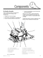
1
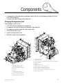
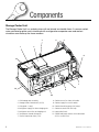
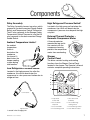
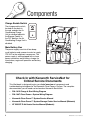
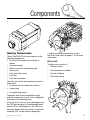
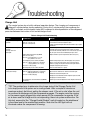
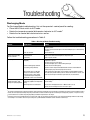
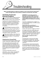
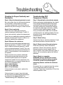
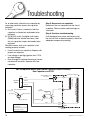
Kenworth
Professional
Service
Workbook
No. 2, 2007 • Volume 80
Featuring:
Kenworth
Clean Power™ System
Fuel-Fired Heater
(in passenger’s
side tool box)
Enhanced Insulation
LED Lighting
Air Conditioning
Charge Unit
High Output Alternator
Starter Batteries Disconnect
Switch (cab floor)
Main Battery
Disconnect Switch
Shore Power
Connector
(120 VAC)
Main Battery Box
Starter Batteries
Main Batteries
Circuit Breaker Box
(in driver’s side tool box)
k
kboo you
r
o
W
ive
This
d to g mponents
e
n
g
i
o
is des rview of c chniques.
e
v
fo
ing te
.
a brie ubleshoot
etails
d
o
r
r
t
o
f
and
e8
ag
See p
Storage Cooler
(under lower bunk)
Components
Kenworth Clean Power™ System Components
Kenworth’s Clean Power™ System is designed
to keep a vehicle’s sleeper cool in summer and
warm in winter for up to 10 hours with no need
to idle the engine.
It’s a battery-powered climate control system,
independent from the cab’s air conditioner
and heater, with its own separate heating and
cooling sources. In addition, there’s enough
battery power so the driver can operate any
120-Volt AC accessories.
Clean Power features and benefits:
CONTENTS
• Clean Power keeps the vehicle in
compliance with all state and federal antiidling regulations, because it operates with
the engine off.
• It provides engine-off sleeper heating,
cooling and operation of A/C devices.
The driver can relax in climate-controlled
comfort with a TV and DVD player before
turning in for the night, all without running
the engine.
Troubleshooting Cooling . . . . . . . . 11
Troubleshooting Heating . . . . . . . . 21
Flow Charts . . . . . . . . . . . . . . . . . 23
Test Your Knowledge . . . . . . . . . . 26
©2007 Kenworth Truck Co., a division of PACCAR.
Produced by Burgio, Cooney & Associates, Independence, MO.
This publication may not be reproduced without the written
permission of Kenworth Truck Company.
Phone: 816-353-3672 • Fax: 816-353-4206
e-mail: [email protected]
2
• With the engine off, there’s no noise or
vibration while the driver sleeps.
• By eliminating all-night idling, fuel economy
is improved and costs are reduced.
Sleeper Cooling Components
Clean Power is a complete system, with all
components designed to function together for
efficient and effective battery-powered cooling
and heating to keep the sleeper comfortable
during the driver’s off hours. Enhanced
insulation makes temperature control more
effective, a high output alternator keeps both
banks of batteries charged while driving, and
LED lighting provides more illumination with
less power draw. Starter Batteries are isolated
and charged by the Main Batteries via a DC/DC
charger which operates only when the ignition
key is ON. The Starter Batteries are charged
while driving, ensuring a full state of charge for
the next startup.
Storage Cooler
The Clean Power System’s Storage Cooler
stores the system’s cooling capacity by freezing
water. As the system is used, the ice melts into
water which is later recharged (frozen) by the
Air Conditioning Charge Unit located on the
right-hand frame rail behind the sleeper. Cold
energy is dispersed as the driver relaxes.
The Storage Cooler consists of:
• A cold storage assembly
• An air-handler assembly
• A cold transfer system, located between
the Storage Cooler and the Air Conditioning
Charge Unit, which uses an automotive
antifreeze solution
Workbook No. 2, 2007 • Volume 80
Components
• A refrigeration system between the Storage Cooler and the Air Conditioning Charge Unit which
uses R134a refrigerant
• A control unit which houses relays and fuses
Charging (Refrigeration) Unit
The charging unit consists of:
• A 120 VAC electrical refrigeration compressor
• A condenser core with an electrical automotive-type radial fan
• An evaporator (located inside the cold storage core)
• A thermal expansion valve
• A pressure equalization valve
2
• Electrical circuitry and components
3
1
2
1
4
3
11
5
9
4
10
8
5
7
9
8
6
7
6
1. Condenser inlet connection
2. Condenser fan - Radial
3. Positive Temperature Coefficient Resistor (PTCR)- compressor hard-starting aid
4. Refrigerant filter/dryer
5. Accumulator
1. High refrigerant pressure switch
2. Low refrigerant pressure switch
3. Service port - High pressure liquid side
4. Run capacitor
5. Condenser
6. Condenser outlet connection
6. 120 VAC power connection
7. Refrigerant supply line to TXV and evaporator
8. Refrigerant return line from TXV and evaporator
9. Hermetic compressor for R134a refrigerant system
10. Cover for electrical connections and thermal/overload protector
11. Ambient temperature limiter
7. 12 Volt wiring harness and connector
8. Service port - low pressure gas side
9. Magnetic equalization (bypass) valve
Workbook No. 2, 2007 • Volume 80
3
Components
Storage Cooler Unit
The Storage Cooler Unit is a sealed system with no internal serviceable items. A vacuum sealed,
water saturated graphite matrix interlaced with a refrigeration evaporator core and coolant
circulation core make up the freeze medium.
3
1
4
5
2
6
13
7
12
9
11
10
1. Cold storage core assembly
8. Coolant return line from air handler
2. Storage Cooler Control Unit (SCCU)
9. Coolant supply line to air handler
3. Lifting bolt - 3 total
10. Coolant circulating pump (AC pump)
4. Refrigerant supply line from charging unit
11. Coolant reservoir with filler cap
5. Refrigerant return line to charging unit
12. Large pallet (base)
6. Temperature control thermostat
13. Control and power harness with connectors
SCCU-1 and SCCU-2
7. Thermal eXpansion Valve (TXV)
4
8
Workbook No. 2, 2007 • Volume 80
Components
Air Handler Assembly
• A motor-actuated door to switch from fresh
air to recirculated air
The air handler assembly is in the central
compartment of the storage cooler.
It consists of:
• A liquid-to-air heat exchanger
• A low power consumption air circulation fan
General Description
• Fresh air and recirculated air intake ducts
1
2
When fresh air mode is selected, filtered air
is drawn in from an opening in the lower rear
sleeper panel. The filter is a replaceable Hepa
cartridge.
Condensation drains through an opening in the
bottom of the air handler and vehicle floor.
3
12
11
4
5
10
9
8
7
6
1. Cover - Air filter housing and filter
6. Coolant inlet from cold storage unit
2. Port - Access to heat-exchanger bleeder valve
7. Coolant outlet to cold storage unit
3. Conditioned air outlet
8. Connection Socket - Mode door actuator
4. Fan and scroll housing
9. Motor - Mode door actuator (Fresh/Recirculated)
5. Small pallet (Base)
10. Fresh air inlet
11. Cabin temperature sensor (Recirculated air mode)
Figure 5. Air Handler Assembly
Workbook No. 2, 2007 • Volume 80
12. Recirculated air inlet
5
Components
Storage Cooler Control Assembly
Temperature Control Thermostat
The Storage Cooler system is designed to
automatically recharge when the cold energy
in the Storage Cooler is depleted. To monitor
and control the parking cooler, the cold transfer
system uses:
• Storage Cooler Control Unit (SCCU)
• Temperature control thermostat
• Ambient temperature limiter
• High refrigerant pressure switch
• Low refrigerant pressure switch
• Charge enable switch (located on the dash)
• Sleeper control panel (located in the
sleeper)
• High/low refrigerant pressure cutout
switches and compressor overheat/
overload protection
• Relay Assembly (located in driver’s side tool
compartment)
The thermostat is mounted on the refrigerant
suction line. It allows system charging or no
system charging, depending on storage core
temperature at the suction line.
Storage Cooler Control Unit (SCCU)
The SCCU is located on top of the cold storage
unit and is critical for ensuring that the storage
cooler portion of the Clean Power System
functions properly.
Cold Transfer System
The cold transfer system, or coolant circuit, is
made up of a circulating pump, coolant hoses,
coolant reservoir and transfer medium (50/50
mixture of extended life coolant [ELC] and
water).
A sensor mounted in the recirculated air duct
monitors sleeper temperature, prompting the
A/C pump to switch on and off and circulate
coolant.
6
2
1
3
1 Supply from cold storage unit
2 Coolant reservoir
3 A/C circulating pump 12 Volt
6
4 5
4 Inlet to air handler
5 Return from air handler
6 Return to cold storage unit
Workbook No. 2, 2007 • Volume 80
Components
Relay Assembly
High Refrigerant Pressure Switch*
The Relay Assembly houses two relays which
respond to the dash-mounted Charge Enable
Switch and Temperature Control Thermostat.
The K2 relay responds to the Storage Cooler
Temperature Control Thermostat, and the K8
relay responds to the dash-mounted Charge
Enable Switch.
Located in the high-pressure line before the
condenser, the switch will deactivate the
compressor if pressure rises beyond the high
set point.
R
Thermal Protector
S
An ambient
temperature
limiter is
located on the
condenser
fan shroud. It
deactivates the
sleeper cooling
system during
cold weather.
A thermal protector
mounted on top and in
firm contact with the
compressor housing
protects the compressor
motor from overheating.
C
Ambient Temperature Limiter*
External Thermal Protector –
Hermetic Compressor Motor
Sleeper
Control Panel
Low Refrigerant Pressure Switch*
Located in the high-pressure line after the
condenser, this switch deactivates the
compressor in a low pressure situation due to
refrigerant loss.
The driver controls heating and cooling
functions from the Sleeper Control Panel
located in the sleeper. The Operator’s Manual
contains complete operating instructions.
1
2
9
OFF
3
4
5
NORMAL
6
Low Pressure
8
OFF/RESET
7
High Pressure
1. Temperature
Control Dial
5. Shore Power LED
(120 VAC)
2. AC Circulation
Pump LED
6. Air Conditioning/
Heating Switch
3. Green Snowflake
7. Inverter/Charger Switch
4. Inverter/Charger LED
8. Fresh Air/Recirculated
* Located in the Charging Unit
Workbook No. 2, 2007 • Volume 80
7
Components
Charge Enable Switch
The charge enable switch,
located on the dash in
the cab, enables the Air
Conditioning Charge
Unit to refreeze/replenish
the Storage Cooler. In
the OFF position, the Air
Conditioning Charge Unit is
disabled.
CHARGE
Main Battery Box
The power supply consists of four deepcycle batteries and a power inverter to supply
120 VAC to the refrigerant compressor. The
power supply is also equipped with a shore
power connection and a battery charger for
stand-alone, engine-off operation and battery
charging.
Check In with Kenworth ServiceNet for
Critical Service Documents
This Workbook is designed to give you a brief overview of components and
troubleshooting techniques for the Kenworth Clean Power™ System. The complete
documentation you will need can be found on Kenworth ServiceNet:
• P94-1613 Charge & Start Wiring Diagram
• P94-1667 Clean Power™ System Wiring Diagram
• Kenworth Clean Power™ System Service Manual
• Kenworth Clean Power™ System Storage Cooler Service Manual (Webasto)
• AT 2000 ST-D Air Heater Service Manual (Webasto)
8
Workbook No. 2, 2007 • Volume 80
Components
Heating Components
The Air Top 2000 ST air heater consists of the
following components:
• Drive unit with combustion and hot air
blower
• Heat exchangers
• Burner insert with combustion pipe
• Control unit
• Fuel “metering” pump
• Fuel filter
• Fuel tank stand pipe
Internally, the control and monitoring system is
made up of:
• A control unit with temperature sensor
if Webasto’s optional interface kit is used.
See Error Code chart on page 21-22 for more
information.
Drive Unit
The drive unit consists of:
• The drive motor
• The combustion air blower
• The hot air blower
• The intake casing
• A glow plug
• An overheating sensor
The heater also can be controlled using an
external temperature sensor. Fuel is supplied to
the heater via a metering pump.
In the event of a fault, an error code appears on
the CPS control panel Air Conditioning/Heater
switch LED as a flashing pulse. The LED is on
the lower (heater) half of the switch. A personal
computer (PC) can be used for diagnostics,
Workbook No. 2, 2007 • Volume 80
9
Components
Heat Exchanger
The heat exchanger
transfers heat from
the combustion
process to the air
stream generated by
the hot air blower.
will be shut down and cold air blown over the
heat exchanger if the control unit detects a
hot air outlet temperature of more than
150°C (302°F) and surface temperatures over
80°C (176°F) . Should this shutdown occur, the
heater can be restarted by being switched off
and then on again.
Fuel Metering Pump
Burner Insert with
Combustion Pipe
The metering pump supplies fuel from the
truck’s fuel tank to the heater. It is a combined
transport, metering and shut-off system.
The fuel-air mixture
distributed over the cross
section of the combustion
pipe in the burner insert
burns to heat the heat
exchanger.
Fuel Filter
A Webasto filter
P/N 487171 is the only
approved fuel filter for use
in the heating system.
Control Unit
The control unit ensures proper function
of the heater and monitors its operation.
A temperature sensor controls sleeper
temperature, and an external sensor may also
be connected to the heater.
If a fault occurs, the Air Conditioning/Heater
switch LED will flash. The heater also can be
checked using a PC with Webasto’s optional
interface kit.
Glow Plug
A glow plug positioned in the burner insert on
the side away from the flame ignites the fuel-air
mixture when the heater is started.
Overheating Sensor
When the heater is in operation, an overheating
sensor monitors temperatures in the rib area of
the heat exchanger. The combustion process
10
Fuel Extractor
(Stand Pipe)
The fuel extractor (stand
pipe) allows fuel to be
supplied to the heater
from the vehicle’s tank.
Because it is a separate
fuel pickup device, any
effect of pressure is
eliminated.
Workbook No. 2, 2007 • Volume 80
Troubleshooting
Before performing any troubleshooting, it is essential to study the Kenworth Clean Power™
System Storage Service Manual, as well as the Kenworth Clean Power™ System Operator’s
Manual, which are now available for download on ServiceNet.
Sleeper Cooling System
Once bulk charging is complete, the regulator
ramps current and voltage down, and activates
an output pin (to ground) which controls the K9
relay to start the compressor.
Before beginning any troubleshooting on the
Storage Cooler, perform the following checks:
1. Ensure that the “Charge Enable/Disable”
switch located on the dashboard is
functional and in the enabled (up) position.
Note: The LED light will not illuminate unless
the compressor is running.
When in Shore Power mode, you just need
shore power plugged in to activate the shore
power signal (which comes from the Sleeper
Control Panel) to the K10 relay, which will start
the compressor. Shore power works this way
because the power to start the compressor
is coming directly from the wall plug, and the
inverter is bypassed altogether.
2. Ensure that battery voltage is at an
acceptable voltage level as determined by
voltage regulator when engine is running
OR shore power connected.
3. Ensure that 120 VAC voltage is present if
connected to Shore Power.
4. Ensure that the control panel is operative
and functioning properly.
NOTE: As a minimum, all supporting
components, e.g., the Main Battery Box
and control panel that the bunk cooling
system relies upon, must be operational and
within required parameters before proper
troubleshooting of the system can
be performed.
When the truck engine is running and you
are using the inverter only (no shore power),
the voltage regulator for the alternator is
what determines if the battery has an
acceptable charge.
The voltage regulator will go through several
stages of charging. The first is known as bulk
charging. The regulator ramps up the alternator
to provide maximum current and will charge
the batteries at 14.6V. It then looks at the
battery temperature and battery voltage to see
how rapidly the batteries are taking a charge.
Bulk charging lasts a minimum of 30 minutes.
X4 (M5) FRESH/RECIRC
DOOR ACTUATOR
X5 (TS3) TEMPERATURE SENSOR
F = Fuses
A = Amps
K = Relays
TCI = Thermostat Module
K1
F3 (20A)
F7 (2A)
F5 (5A)
F2 (5A)
F6 (7.5A)
K3
K7
K6
TC1
K10
K9
X3 (M4)
COOLANT PUMP
SCCU1
C
B
A
D
E
F
SCCU1
A SCCU2
B
C
D
C
G E
D BF
E
H
F
A
SCCU1
G
H
J
K
L
A SCCU2
B
C
G
D F
E
H
SCCU2
M
J
Workbook No. 2, 2007 • Volume 80
X2 (M3)
BLOWER FAN
G S
M
NH R L
M PJ
K
L
P,S,R NOT USED
K
J
S
R
N
M P
L
P,S,R NOT USED
K
11
Troubleshooting
Storage Cooler Control Unit (SCCU)
Before troubleshooting the SCCU:
• Disconnect connectors SCCU 1 (12-pin)
and SCCU 2 (16 pin).
• Remove the SCCU cover.
• Apply 12-volt power to pins G/12 and
H/12 of connector SCCU 1.
NOTE: Power and ground must be maintained
throughout the SCCU testing process.
• Apply ground to pins J/12 and K/12 of
connector SCCU 1.
• Follow the procedures in Table 1.
Table 1. SCCU Troubleshooting Functional Checks
Function
Possible Cause for Malfunction
Remedy
Check for power out (12V) on pin F/12.
Check for open fuse F2.
Check for open or short circuit within SCCU wiring.
Replace fuse F2.
Repair SCCU wiring.
Check for power out (12V) on pin M/16.
Check for open fuse F6.
Check for open or short circuit within SCCU wiring.
Replace fuse F6.
Repair SCCU wiring.
Check for power out (12V) on pin B/12
(Condenser fan) with power (12V)
applied to pins E/12 and M/12.
Check for open fuse F3.
Check relay K10 and socket for power (12V) on pins 1, 3
and 5. Ground on pin 2.
Check relay K1 and socket for power (12V) on pins 86, 30
and 87. Ground on pin 85.
Replace fuse F3.
Repair open or short circuits.
Replace defective relay K10.
Repair open or short circuits.
Replace defective relay K1.
1Check
for power out (12V) on pin D/12 (Magnetic
Valve) for first 2 minutes with power (12V) applied
to pins E/12 and M/12.
Check for open fuse F2.
Check relay K3 and socket for power (12V) on pins 30, 15
and 87a. Ground on pin 31.
Note: Pin 87a will have power for 2 minutes only, after
which it will switch to pin 87.
Replace fuse F2.
Repair open or short circuits.
Replace defective relay K3.
1Check
for power out (12V) on pin A/12
(Compressor) after 2 minutes with power (12V)
applied to pins E/12 and M/12.
Check for open fuse F2.
Check relay K3 and socket for power (12V) on pins 30, 15
and 87. Ground on pin 31.
Replace fuse F2.
Repair open or short circuits.
Replace defective relay K3.
Check for power out (12V) on pin A/3 (Blower
Motor connector X3) with power (12V) applied to
pins H/16 and variable voltage (0... 10V) to pin
L/16 (Blower control signal).
Check for open fuse F6.
Check relay K6 and socket for power (12V) on pins 1, 3 and
5. Ground on pin 2.
Replace fuse F6.
Repair open or short circuits.
Replace defective relay K6.
2Coolant
Check for open fuse F5.
Check thermostat module TC1 and socket for power (12V)
on pins 1, 2 and OUT.
Ground on pin 31.
Replace fuse F5.
Repair open or short circuits. Replace
defective thermostat module TC1.
pump circuit check:
Connect a 2K linear potentiometer between pins
K/16 and J/16. Connect temperature sensor TS3
to X5 connector pins A/2 and B/2. Connect power
(12V) to pin G/16. Check for power out (12V) on
pin N/16 and power out (12V) on connector X3,
pin A/2.
1When
E/12 and M/12 are powered the Condenser Fan (M2) is ON and the Magnetic Valve (MV) is open for the first two minutes. When two minutes have
elapsed the Condenser Fan is ON and Relay K2 is closed (Compressor ON). At this time MV remains closed (no power on D/12) until power is removed from
pins E/12 and M/12.
2When potentiometer is set to 0 ohms, no power out on connector SCCU2, pins D/16 and N/16 and no power out on connector X3, pin A/2.
12
Workbook No. 2, 2007 • Volume 80
Troubleshooting
Table 1. SCCU Troubleshooting Functional Checks, continued
Function
Fresh Air/Recirc. actuator circuit check:
Connect power (12V) to pin A/16 and ground to
pin B/16.
Check for power out (12V) on connector X4, pin 5
(Actuator rotation CW).
Connect power (12V) to pin B/16 and ground to
pin A/16.
Check for power out (12V) on connector X4, pin 6
(Actuator rotation CCW).
Possible Cause for Malfunction
Remedy
Check for open or short circuit within SCCU wiring.
Repair open or short circuits.
Check for open or short circuit within SCCU wiring.
Repair open or short circuits.
Check In with Kenworth ServiceNet for
Critical Service Documents
This Workbook is designed to give you a brief overview of components and
troubleshooting techniques for the Kenworth Clean Power™ System. The complete
documentation you will need can be found on Kenworth ServiceNet:
• P94-1613 Charge & Start Wiring Diagram
• P94-1667 Clean Power™ System Wiring Diagram
• Kenworth Clean Power™ System Service Manual
• Kenworth Clean Power™ System Storage Cooler Service Manual (Webasto)
• AT 2000 ST-D Air Heater Service Manual (Webasto)
Workbook No. 2, 2007 • Volume 80
13
Troubleshooting
Charge Unit
The control system has a built-in delayed operation feature. The charging unit compressor is
delayed 2 minutes before starting operation. During this 2 minute period, the condenser fan
motor (M2) is activated, and the bypass valve (MV) is opened to allow equalization of the refrigerant
pressures between the suction circuit and discharge circuit.
Table 2: Charge Unit Troubleshooting
Concern
Possible Cause
Remedy
Charge unit does not begin
operation.
Core temperature control thermostat (S4) OPEN
Opens at -3.3°C (26.1°F).
Closes at 13.6°C (56.5°F).
*Confirm charge state of cold storage assembly. If fully charged, it
is normal for the thermostat (S4) to be open.
If partly or fully discharged and thermostat remains open, replace
thermostat.
Charge unit does not begin
operation.
*Storage cooler unit
discharged.
Open sensor/pressure switch circuits.
Disconnect 8-pin connector at the charge unit. Check for
continuity across pins A/8 and C/8 of the charge unit side of
connector. No continuity indicates one or more sensors (S2, S6 or
S7) are open. Check sensors individually for open circuit.
Replace limiter if open at temperatures above 16°C (61°F)
Ambient temperature limiter (S6) OPEN.
Opens at 7.2°C (45°F).
Closes at 12.8°C (Tolerance of ± 3.3°C).
55°F (Tolerance of ± 6°F).
Low refrigerant pressure switch (S2) OPEN.
Opens at >1.03 bar (Tolerance of ± 0.24 bar).
>15 psig (Tolerance of ± 3 psig).
Closes at 2.13 bar (31 psig).
High refrigerant pressure switch (S7) OPEN.
Charge unit shuts down after
partial system charge.
High refrigerant pressure switch (S7) OPEN.
Opens at <20.68 bar (Tolerance of ± 0.69 bar)
<300 psig (Tolerance of ±10 psig)
Closes at 12.4 bar (180 psig.)
Core temperature control thermostat (S4) OPENS
prematurely.
Confirm refrigerant pressures with A/C gauge set. If pressure
above 1.27 bar (18 psig), replace sensor. If pressure below
0.8 bar (12 psig), check system for leaks and repair. Perform
complete refrigerant system service.
Pressure switch defective - replace.
Air flow over condenser blocked. Clear obstruction.
Open circuit to condenser fan. Check circuits and repair.
Condenser fan defective. Replace fan.
Refrigerant circuit blocked. Confirm refrigerant pressures with
A/C gauge set. Clear obstruction.
Confirm open state with digital ohm meter. Replace thermostat.
*TIP! The quickest way to determine the charge state of the Storage Cooler Unit
is to simply switch the system on in cooling mode. After a couple of minutes on
maximum output, feel the air exiting the sleeper vents. If the air is cold, allow the unit
to continue to discharge until the compressor engages. The engine must be running
or the power supply plugged into shore power for the compressor to operate. If the
air is warm and the charge unit is not responding, there is a system malfunction. For
this test, ensure that the “Charge Enable/Disable” switch located on the dashboard
is functional and in the enabled (up) position. Note that the LED light will not
illuminate unless the compressor is running.
14
Workbook No. 2, 2007 • Volume 80
Troubleshooting
Discharging Mode
For Discharge Mode troubleshooting, first set the operator’s control panel for cooling:
• Place the AC/Heat switch to A/C mode.
• Rotate the temperature control dial counter clockwise to A/C mode1.
• Rotate the fan control dial clockwise to turn on fan.
Follow the troubleshooting procedures in Table 3.
Table 3. Discharge Mode Troubleshooting
Concern
Possible Cause
Remedy
Blower fan does not turn on.
No power to blower fan (M3).
Blower fan defective.
Check blower fan electrical connector X2 for power out (12V) on pin A/3 and
ground on pin C/3.
Check for open fuse F6 and replace. Check for damaged, open or shorted wiring
and repair.
Replace blower fan.
Blower fan operates with
little or no air flow.
Air ducts blocked.
Air filter dirty.
Ensure correct vents and return grilles in sleeper are open.
Clean or replace air filter.
No cooling of air.
No power to coolant circulating
pump (M4).
Check circulating pump electrical connector X3 for power out (12V) on pin A/2
and ground on pin B/2.
Check for open fuse F5 and replace.
Check for damaged, open or shorted wiring and repair.
Replace coolant circulating pump.
Replenish coolant with premixed 50/50 solution of water and extended life
coolant (ELC) to proper level and purge air from circuit.
Thaw system, drain and fill with correct strength of premixed 50/50 extended
life coolant (ELC) solution. Allow system to circulate for minimum of 15 min. and
check coolant strength. If still weak, repeat drain, fill, circulate and test.
Coolant circulating pump defective.
Low coolant (pump cavitation).
2No circulation due to ice-blocked
storage core coolant tubes. Weak
antifreeze solution or water added
to system without prior mixing with
extended life coolant as recommended.
Cannot control sleeper
Coolant circulating pump runs
cooling temperature. Cold
continuously regardless of temperature
storage unit quickly depleted. setting.
Cabin temperature sensor defective.
Check for unplugged cabin temperature sensor (TS3) connector X5 or open
circuit in wiring.
Check sensor with digital ohm meter. 1.001kW at 24°C (75°F).
Replace sensor if reading is incorrect or sensor is open.
1The
coolant circulating pump responds according to cabin temperature and position of the temperature control dial. The further counter-clockwise the dial is
turned, the more frequently and longer the pump is activated to circulate coolant through the heat exchanger. For diagnostic purposes, it may be necessary
to turn the dial full on to activate the pump, depending on ambient temperatures in the sleeper.
2Pure water must never be introduced into the coolant circuit, under any circumstances! Doing so may cause freezing and blockage within the cold storage
unit resulting in no circulation and no sleeper cooling. Use a premixed 50/50 extended life coolant and water solution only!
Workbook No. 2, 2007 • Volume 80
15
Troubleshooting
Before troubleshooting for compressor problems, refer to the Kenworth Clean Power™
System Storage Cooler Service Manual available for download on ServiceNet.
Identifying Compressor
Electrical Problems
It is critical to follow all safety precautions
when checking for electrical problems.
Never energize a system unless the protective
terminal cover is securely fastened and the
compressor is properly connected to ground.
Be alert for sounds of arcing (sputtering or
popping) inside the compressor. If you hear
such sounds, move away from the area
immediately.
Oil and refrigerant can spray out of the
compressor if one of the terminal pins is
ejected from the hermetic terminal. This can
occur as the result of a ground fault, and spray
can be ignited by electricity. Never energize a
compressor that has a ground fault.
Never reset a breaker or fuse without first
checking for a ground fault; an open fuse
or tripped circuit breaker is a strong ground
fault indicator.
Checking for a Ground Fault
Disconnect all electrical power supplies to the
system, making sure all power legs are open.
Then remove the protective terminal cover.
If you find evidence of overheating at any
lead, that could indicate a compressor motor
problem exists. Do not replace or attach any
leads or connectors that have been damaged
by overheating until the problem has been
repaired.
Disconnect leads and/or remove all
components, such as relays and capacitors,
from the terminal pins. When removing a
current type relay, keep it upright.
16
WARNING: If a capacitor is present,
discharge it using a 20,000 ohm resistor
before removing it from the system. An
undischarged capacitor presents a risk of
electrical shock and damage to measuring
devices.
Use either a megaohmmeter (“megger”) or a
Hi-Potential Ground Tester (“Hi-Pot”) to check
for a ground fault.
Always follow the manufacturer’s
procedures and safety recommendations
when using these devices.
Connect one lead of the megger or Hi-Pot to
the copper suction line, and the other lead
to one of the terminal pins. Repeat for all
terminal pins. If resistance reads less than two
megaohms between any pin and the housing
(copper suction line), a ground fault exists.
Never energize a compressor with a
ground fault.
If a ground fault is found, keep the power
off and replace the compressor. If you do
not replace it immediately, mark and red tag
it, insulating and taping each power lead
separately.
If no ground fault is found, leave the power
off and components disconnected from the
terminal pins. Check for continuity and proper
resistance to determine whether there is an
open or short circuit in the motor windings or
if the heater element of the thermal protector
is open.
Workbook No. 2, 2007 • Volume 80
Troubleshooting
Checking for Proper Continuity and
Resistance
Troubleshooting PSC
Compressor Circuits
Step 1: Allow the thermal protector to reset.
Be sure to allow time for the thermal protector
to reset before starting electrical checks.
For some compressors, the internal thermal
protector may take as long as an hour to reset.
Step 1: Ground fault and continuity checks.
Before continuing troubleshooting, you should
have already disconnected electrical power
and should have checked for ground faults.
You also should have checked the windings
for continuity and proper resistance, making
sure the system is getting proper voltage.
And, you should have made sure all controls
and thermostats are working properly. Be sure
to perform these checks before continuing
troubleshooting.
Step 2: Check continuity.
Check the start winding by measuring
continuity between terminal pins C and S. If
there is no continuity, replace the compressor.
Check the run winding by measuring continuity
between terminal pins C and R. If there is no
continuity, replace the compressor.
Step 3: Measure the resistance.
Measure the resistance (ohms) between each
pair of terminal pins: C and S, C and R, and S
and R. Add the resistance between C and S
to the resistance between C and R. This sum
should equal the resistance found between S
and R. A small deviation in this comparison is
acceptable.
Proper resistance may also be confirmed
by comparing measured resistance to the
resistance specifications for the specific
compressor model. For this compressor, the
resistance values at a nominal temperature of
21°C (70°F) should be within:
C&S = 4.0 to 5.2 ohms
C&R = 0.7 to 0.85 ohms
S&R = 4.7 to 6.05 ohms
If the resistance is not correct, replace the
compressor.
Step 2: Check wiring.
Confirm that there is continuity between C and
the thermal protector common lead wire.
Step 3: Check external thermal protector.
Check for continuity across the thermal
protector. If there is no continuity, then the
thermal protector may be tripped. Wait at
least 5 minutes, then check continuity again. If
there is still no continuity, replace the thermal
protector.
Step 4: Check run capacitor.
WARNING: Using a 20,000 ohm resistor,
discharge the capacitor before removing
it from the system to avoid damage to
measuring devices and the risk of electric
shock.
Disconnect the run capacitor from the system.
Use a capacitance meter to check the
capacitor. Capacitance should be ±10% of the
marked capacitor value.
If the resistance is correct, leave the leads
off and continue troubleshooting procedures
as outlined in the following Steps 1-6,
“Troubleshooting PSC Compressor Circuits.”
Workbook No. 2, 2007 • Volume 80
17
Troubleshooting
As an alternative, check the run capacitor by
measuring continuity across the capacitor
terminals:
A. Rx1 scale: If there is continuity, then the
capacitor is shorted out and needs to be
replaced.
B. Rx100,000 scale: If a digital multi-meter
(DMM) indicates infinite resistance, then
the run capacitor is open and needs to be
replaced.
Possible reasons that a run capacitor is not
working properly include:
• Use of incorrect run capacitor. Replace with
proper run capacitor.
• Line voltage is too high (greater than 110%
of rated voltage).
• Rust-through of capacitor housing or severe
corrosion of terminals. Replace with new
capacitor.
Step 5: Reconnect run capacitor.
Reconnect the run capacitor into the circuit
as before. Observe color code markings on
schematic.
Step 6: Continue troubleshooting.
If all the above tests prove satisfactory and
the unit still fails to operate properly, check for
adequate compressor pumping.
PSC Compressor Motor with External Thermal/Current Protector,
Run Capacitor and PTCR
Black
C
Red
S
White
R
White
Green
X1 - 120 VAC RECEPTACLE
Locking Tab
Black (Hot)
Run
Capacitor
Blue
White (Neutral)
Main Motor Winding
120 VAC
INPUT
Black
Compressor Casing
Overheat/Overload
Protector
Start Winding
X1
X2
Blue
Green (Ground)
PTC Resistor
White
PSC Compressor with:
- run capacitor
- external thermal protector
- PTC resistor (wired)
18
Green
X4
Compressor Casing
Ground
Workbook No. 2, 2007 • Volume 80
Troubleshooting
Refrigerant Compressor
Never troubleshoot, service or repair a refrigerant compressor unless you are a certified
professional air conditioning/refrigeration technician. Improper procedures can lead to serious
injury or death from fire, electric shock or explosion.
Follow the troubleshooting procedures in Table 4.
Table 4. Refrigerant Compressor Troubleshooting
Symptom
Possible Causes
Remedy
Compressor will not start – no
audible hum.
Thermal protector not working properly.
*See “Identifying Compressor Electrical
Problems”.
Wiring improper or loose.
Check against wiring diagram and wire properly.
Compressor motor has a ground fault (also known as a short
circuit to ground).
*See “Identifying Compressor Electrical
Problems”.
Improperly wired.
Check against wiring diagram and wire properly.
Low voltage to compressor.
Turn off system until proper voltage is restored.
Compressor electrical problems:
a. Compressor motor has a winding open or shorted.
b. Start capacitor or PTCR not working properly.
c. Relay does not close.
*See “Identifying Compressor Electrical
Problems”.
Compressor will not start – hums
but trips on thermal protector.
Compressor starts, but does not
switch off of start winding.
Internal mechanical troubles in compressor.
*See “Checking for Adequate Compressor
Pumping”.
Improperly wired.
Check against wiring diagram and wire properly.
Low voltage to compressor.
Turn off system until proper voltage is restored.
Compressor electrical problems:
a. Compressor motor has a winding open or shorted.
b. Relay failing to open.
c. Run capacitor not working properly.
*See “Identifying Compressor Electrical
Problems”.
Discharge pressure too high.
Compressor starts and runs, but
short cycles on thermal protector.
Internal mechanical trouble in compressor.
*See “Checking for Adequate Compressor
Pumping”.
Too much current passing through thermal protector:
a. Extra sources of current draw.
b. Compressor motor has winding shorted.
Check for extra sources of current passing through
thermal protector, such as fan motors, pumps.
(This would be extremely rare as the system is not
designed for such use.).
*See “Identifying Compressor Electrical Problems”.
Low voltage to compressor.
Turn off system until proper voltage is restored.
Compressor electrical problems, such as thermal protector or run
capacitor not working properly.
Discharge pressure too high.
*See “Identifying Compressor Electrical Problems”.
Suction pressure too high.
Return gas too warm.
Check condenser fan for malfunction.
*See “Kenworth Clean Power™ System Storage Cooler Service Manual” for details. Now available on ServiceNet to download.
Workbook No. 2, 2007 • Volume 80
19
Troubleshooting
Table 4. Refrigerant Compressor Troubleshooting, continued.
Symptom
Possible Causes
Unit runs OK, but run cycle is
shorter than normal (due to
component(s) other than thermal
protector).
System components, such as storage temperature control
thermostat, SCCU, relays, not functioning properly.
High pressure cut-out due to:
a. Insufficient air flow over condenser.
b. Overcharge or refrigerant.
c. Air in system.
Remedy
*See “Troubleshooting”.
Low pressure cut-out due to:
a. Refrigerant leaking.
b. Undercharge of refrigerant.
c. Restriction in thermal expansion valve.
Unit operates long or
continuously.
Undercharge of refrigerant.
System components, such as digital temperature sensor, control
module, relays, not functioning properly.
Restriction in refrigeration circuit.
Dirty condenser.
Check for leak and correct. Perform full refrigerant
service on system.
*See “Compressor Replacement and System
Service” and “Component Replacement Refrigeration Unit”.
Suction line frosted or sweating.
System problems, such as:
a. Expansion valve stuck open.
b. Overcharge of refrigerant.
*See “Compressor Replacement and System
Service” and “Component Replacement Refrigeration Unit”.
Liquid line frosted or sweating.
System problems, such as restriction in dehydrator or strainer.
*See “Compressor Replacement and System
Service” and “Component Replacement Refrigeration Unit”.
System rattles or vibrates during
operation.
Loose parts or mountings, tubing rattle, bent fan blade causing
vibration, fan motor bearings worn, etc.
Repair or replace loose, worn, defective parts.
*See “Kenworth Clean Power™ System Storage Cooler Service Manual” for details. Now available on ServiceNet to download.
20
Workbook No. 2, 2007 • Volume 80
Troubleshooting
Refer to the Webasto AT 2000 ST-D Air Heater Service Manual for complete troubleshooting
information available for download on ServiceNet.
Heating System
Troubleshooting
Webaso Heater
Adapter Harness
P/N 92555A
Before troubleshooting the sleeper heating
system check the following items so they
can be eliminated as possible causes for the
particular fault:
• Corrosion on plugs
• Loose plug contacts
• Poor crimp contacts on plugs
• Corroded cables and fuses
• Corroded battery terminals
To check individual components, first
disconnect electrical plug connectors on the
control unit.
Webaso Diagnostic Interface Kit
P/N 9009064D
If a fault occurs, an error code will be visible
in the display of the combination timer, and
the heater element ON control light will flash.
The heater also can be diagnosed using a
PC if Webasto’s optional diagnostic interface
kit and software are used. The interface kit
and adapter harness can be ordered through
PACCAR Parts.
Error Code Output
If a fault occurs, an error code will appear on the combination timer display. The table below lists
Error Codes F 00 through F 15, as well as their personal computer diagnostic counterparts.
Error code Error (group)
Additional information during PC diagnostic
Remedy
F 00
Control unit error
01 Control unit error.
81 EOL checksum error.
11 Incorrectly coded control unit or incorrect heater (fuel type) installed (the
heater will not work if this error occurs).
91 Neutrally coded or disabled control unit (the heater will not work if this
error occurs).
92 Maintain command failed (the heater will not work if this error occurs).
18 Customer bus defective.
Replace control unit.
F 01
No start
02 Even after the restart, no flame has formed.
Check fuel supply (tank empty, lines
blocked). Clean burner insert.
Replace overheating sensor/control
unit.
82 No start in test.
F 02
Flame failure
Workbook No. 2, 2007 • Volume 80
03 The flame has gone out during operation and has not reformed after a
restart attempt.
83 The flame has gone out during a heating cycle more than 3 times.
See 3.7.1. Error (FAZ Flame Failure Counter).
Check fuel supply tank empty, lines
blocked). Clean burner insert.
Replace overheating sensor/control
unit.
21
Troubleshooting
Error code Error (group)
Additional information during PC diagnostic
Remedy
F 03
Undervoltage or
overvoltage.
84 The voltage was less than 10.5 V or 21 V for longer than 20 seconds.
04 The voltage was more than 16 V or 32 V for longer than 6 seconds.
Charge battery.
F 04
Premature flame
recognition.
05 A flame was detected before combustion had started.
Replace overheating sensor/control
unit.
F 05
Not Applicable.
Not Applicable.
Not Applicable.
F 06
External temperature
sensor break or short
circuit.
14 Temperature sensor circuit. Short circuit to earth.
Check cables/replace temperature
sensor.
Check cables and terminating
resistor/replace temperature sensor.
F 07
Metering pump
interrupt or short
circuit.
88 Break or short circuit to +Ub.
08 Short circuit to earth.
Check cables/replace metering
pump.
Check cables/replace metering
pump.
F 08
Drive unit (combustion
and hot air blower)
break or short circuit.
89 Break or short circuit to +Ub.
Replace drive unit (combustion and
hot air blower).
Eliminate the cause of the blockage/
difficulty in movement.
Replace drive unit (combustion and
hot air blower).
94 Temperature sensor circuit break or short circuit to +Ub.
09 The switched drive unit cable (combustion and hot air blower) has a
short circuit to earth or the drive unit is overloaded.
15 Burner motor block guard has tripped.
95 Burner motor blocking detection has tripped.
F 09
Glow plug interrupt or
short-circuit.
8A Glow plug: Break or short circuit to +Ub.
19 Glow circuit: The switched cable of the element has a short circuit to
earth.
Replace glow plug.
F 10
Overheating.
06 The overheating fault lock-out has tripped (heater overheated).
17 Incorrect application or illegal insulation (ÜHS gradient too high).
Find and remove the cause of the
overheating.
NOTE: If no other cause can be
found for the overheating, the
pressure losses caused by the hot
air distribution (too many resistance
points) are too high or a hot air filter
is soiled.
F 11
Overheating sensor
interrupt or short
circuit.
AB Overheating sensor circuit break or short circuit to +Ub.
1B Overheating sensor circuit. The switched cable of the element has a
short circuit to earth.
Replace overheating sensor.
F 12
Heater fault lock-out.
07 The heater fault lock-out has been activated.
Remove the fuse and then refit it.
NOTE: The following error has
occurred several times:
Fault counter: 3+ times
Incorrect start counter: 9+ times
Overheating counter: 3+ times
F 13
Permanent heater fault 87 The permanent heater fault lock-out has been activated.
lock-out.
F 14
Overheating sensor
incorrect position.
97 Incorrect position of overheating sensor (ÜHS gradient too low).
Position the overheating sensor
correctly.
F 15
Nominal sensor break.
9B Nominal value potentiometer circuit break or short circuit to +Ub.
Check cables/replace control
element.
22
Delete the error with the PC
diagnostic.
NOTE: Permanent flame failure
counter more than 3 times.
Workbook No. 2, 2007 • Volume 80
Flow Charts
Charge State Diagram
A/C Enable Switch Closed (S1)
and
Storage Core Temperature
Control Thermostat Closed (S4)
and
Ambient Temperature
Limiter Closed (S6)
and
High & Low Pressure
Switches Closed (S7/S2)
and
Battery Voltage Acceptable per Voltage
Regulator or Shore Power Connected
and
Inverter 120 VAC Output Present
(K8 Closed)
Charging Unit
OFF
Id = 0
Ia = 0
Id = DC Current (Amps)
Ia = AC Current (Amps)
S = Switch
K = Relay
MV = Magnetic Solenoid Valve
= Function OFF
= Storage Cooler Charging
Workbook No. 2, 2007 • Volume 80
A/C Enable Switch Closed (S1)
and
Storage Core Temperature
Control Thermostat Closed (S4)
and
Ambient Temperature
Limiter Closed (S6)
and
High & Low Pressure
Switches Closed (S7/S2)
and
Battery Voltage Acceptable per Voltage
Regulator or Shore Power Connected
and
Inverter 120 VAC Output Present
(K8 Closed)
and
Elapsed Time >2 min.
Time Delay Relay Closed (K3)
Condenser Fan (K1) ON
Time Delay Relay (K3) Counting Down
Compressor Bypass (MV)
Valve ON (valve opened)
Id = 10
Ia = 0
A/C Enable Switch Open (S1)
or
Storage Core Temperature
Control Thermostat Open (S4)
or
Ambient Temperature
Limiter Open (S6)
or
High & Low Pressure
Switches Open (S7/S2)
or
Battery or Alternator Not Operating at
Acceptable Levels per Voltage Regulator
or Shore Power Disconnected
or
Inverter 120 VAC Output Not Present
(K8 Open)
Compressor Bypass (MV)
Valve OFF (valve closed)
Compressor (K2) ON
Id = 60-70
Ia = 8
A/C Enable Switch Open (S1)
or
Storage Core Temperature
Control Thermostat Open (S4)
or
Ambient Temperature
Limiter Open (S6)
or
High & Low Pressure
Switches Open (S7/S2)
or
Battery or Alternator Not Operating at
Acceptable Levels per Voltage Regulator
or Shore Power Disconnected
or
Inverter 120 VAC Output Not Present
(K8 Open)
23
24
Fresh Air / Recirc
Mode Switch (S5)
OFF
OR
Fresh Air Mode
Switch (S5) Position Up
Recirculation Mode
Switch (S5) Position Down
Blower Switch (S3) ON
OFF
OFF
Blower Switch (S3) ON
Switch to
Fresh Air (S5)
Switch to
Recirculation (S5)
Fresh Air Mode
Switch (S5) Position Up
Recirculation Mode
Switch (S5) Position Down
OFF
Blower Switch (S3) OFF
Switch to
Recirculation (S5)
Switch to
Fresh Air (S5)
Fresh Air, Recirculated Air State Diagram
Flow Charts
Workbook No. 2, 2007 • Volume 80
Workbook No. 2, 2007 • Volume 80
Cooling
System
and
Blower
OFF
Blower Switch (S3) OFF
Coolant Circulating
Pump (M4) ON
Coolant Circulating
Pump (M4) OFF
Rotate Thermostat
CW to LED OFF
or
Return Air ≤
Thermostat (TS3)
Rotate Thermostat
CCW to LED ON
or
Return Air ≥
Thermostat (TS3)
Coolant Circulating
Pump (M4) OFF
Return Air ≤
Thermostat (TS3)
OR
Rotate Thermostat
CCW to LED ON
or
Return Air ≥
Thermostat (TS3)
Rotate Thermostat
CW to LED OFF
or
Return Air ≤
Thermostat (TS3)
Coolant Circulating
Pump (M4) ON
Return Air ≥
Thermostat (TS3)
Blower Switch (S3) OFF and Cooling Switch OFF
Cooling System
ON
Blower Switch (S3) ON
Blower ON
(Minimum 10 CFM)
Cooling Switch ON
OR
Cooling System
ON
Cooling Switch ON
Blower ON
(Minimum 10 CFM)
Cooling Switch OFF
and
Blower Switch (S3) ON
Cooling Switch OFF
= Storage Cooler Circ. Pump ON
(Green LED ON)
= Storage Cooler Circ. Pump OFF
Cooling Discharge State Diagram
OR
OR
Flow Charts
25
Test Your Knowledge
Instructions: Follow the steps on the Answer Sheet on the next page to take your test online, to fax,
or to mail your test.
1. The storage cooler portion of the Clean
Power™ System operates as a standard
refrigeration system, with what difference?
a. It is battery-powered.
b. It is both battery and AC-powered.
c. It stores cold energy for later use.
2. Is a PC necessary for reading error codes if
a heating system fault occurs?
a. Yes
b. No
3. If water is used to top off coolant level
instead of a premixed 50/50 extended
life coolant and water solution, what can
happen?
a. The system can become corroded.
b. Freezing and blockage may occur,
resulting in poor sleeper cooling.
c. The cabin temperature sensor may
not work.
4. Where is fuel stored for the heating system?
a. In the vehicle’s diesel fuel tanks
b. In a tank under the bunk
5. If the blower fan operates properly but
there is reduced or no air flow, what should
you do?
a. Check that the correct vents and return
grills in the sleeper are open and not
blocked.
b. Check for a dirty air filter.
c. Both of the above.
26
6. In shore power mode, the inverter is
bypassed.
a. True
b. False
7. A tripped breaker should be reset before
beginning electrical troubleshooting.
a. Yes
b. No
8. In the event of a fault in the heater system
component, an error code appears as:
a. A steady light on the heater switch.
b. A flashing pulse on the heater switch.
9. If the compressor operates for an unusually
long period of time or runs continuously, and
you have determined there is no leakage or
undercharge of refrigerant, the cause of the
problem might be:
a. A dirty condenser.
b. A malfunctioning relay
c. A restriction in the refrigeration circuit.
d. All of the above
10.The driver cannot control sleeper cooling
temperature and the cold storage unit
depletes quickly. A defective or unplugged
cabin temperature sensor is definitely not
the problem.
a. True
b. False
Workbook No. 2, 2007 • Volume 80
Answer Sheet
Faster, Easier Testing ONLINE!
Take your Professional Service test and get your score instantly, ONLINE! Here’s how:
1. Go to the Kenworth Training page and access the training website in one of two ways:
a. From the Internet, type www.kenworth-training.com into the browser address box.
Click “Go” to display the Kenworth training page –
OR
b. From the Kenworth DealerNet Home Page:
1) Click on the Training tab at the top of the page.
2) Select “Service” from the menu on the left.
3) Select “Kenworth Service Training.”
2. Verify that the displayed log-in information is correct, then click the Submit button.
3. Select the box titled “Workbooks and Update Tests.”
4. Moving the cursor reveals workbook or Update tests you may want to take.
It’s fast and easy, and you’ll see your score instantly!
Good luck!
If you’re faxing or mailing your test, please print your name and dealership information below.
Name:
PRINT ONE LETTER IN EACH BOX. LEAVE A BLANK BETWEEN NAMES AND INITIALS.
Dealership:
Dealer Code:
Address:
City:
State/Province:
Zip or Postal Code:
Mark the box for the correct answer to each test item on previous page. Then fold and mail this Answer Sheet to the
address on the back, or fax to the Kenworth Professional Service Coordinator at Burgio, Cooney and Associates
(816) 353-4206
Kenworth Clean Power™ System
1. abcd
4. abcd
8. abcd
2. abcd
5. abcd
9. abcd
3. abcd
6. abcd
10. abcd
7. abcd
Workbook No. 2, 2007 • Volume 80
27
Kenworth
Professional
Service
Workbook
Featuring:
Kenworth
Clean Power™ System
FOLD AND TAPE
PROFESSIONAL SERVICE WORKBOOK
Burgio, Cooney + Associates
13665 e 42nd terrace s – suite d
independence, mo 64055-7343