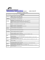
1
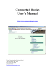
Solar Inverter Service Manual Modular Solar Inverter – HE and HES Series Service Manual Edition: August 2011 FSMS01AI Rev. A FREESUN 2 POWER ELECTRONICS POWER ELECTRONICS FREESUN SAFETY SYMBOLS Always follow safety instructions to prevent accidents and potential hazards from occurring. WARNING CAUTION This symbol means improper operation may results in serious personal injury or death. Identifies shock hazards under certain conditions. Particular attention should be given because dangerous voltage may be present. Maintenance operation should be done by qualified personnel Identifies potential hazards under certain conditions. Read the message and follow the instructions carefully. E N G L I S H Identifies shock hazards under certain conditions. Particular attention should be given because dangerous voltage may be present. Edition of August 2011 This publication could present technical imprecision or misprints. The information here included will be periodically modified and updated, and all those modifications will be incorporated in later editions. To consult the most updated information of this product you might access through our website www.power-electronics.com where the latest version of this manual can be downloaded. SAFETY SYMBOLS 3 FREESUN POWER ELECTRONICS Revisions Date Revision Description 08 / 08 / 2011 A First Edition The equipment and technical documentation are periodically updated. Power Electronics reserves the right to modify all or part of the contents of this manual without previous notice. 4 POWER ELECTRONICS FREESUN INDEX SAFETY INSTRUCTIONS ........................................................................................................... 6 1. NOTES ON THIS MANUAL ................................................................................................. 1.1. Scope of Validity .......................................................................................................... 1.2. Target Group ................................................................................................................ 1.3. Documentation ............................................................................................................. 10 10 10 10 2. INTRODUCTION .................................................................................................................. 2.1. Maintenance Tasks in Freesun Inverter ....................................................................... 2.2. Maintenance Tasks in Freesun String Supervisor ........................................................ 10 11 12 3. MAINTENANCE OF THE FREESUN ................................................................................... 3.1. Identifying the Freesun ................................................................................................. 3.2. Reading out Historical Data and Errors ........................................................................ 3.3. Cleaning the Electronic Parts ....................................................................................... 3.4. Cleaning the Protective Grids at the Air Inlets and Outlets........................................... 3.5. Checking the Inside of the Switch Cabinet ................................................................... 3.6. Checking the Power Cable Connections ...................................................................... 3.7. Checking the Safety Notices ........................................................................................ 3.8. Checking the Fans ....................................................................................................... 3.9. Checking the Heating and the Hygrostat ...................................................................... 3.10. Checking Protective Devices........................................................................................ 3.11. Checking the Cable Feed of the Concrete Substations (Freesun HES) ....................... 13 13 13 13 14 17 17 17 17 17 18 20 4. MAINTENANCE OF THE FREESUN STRING SUPERVISOR ............................................ 21 INDEX E N G L I S H 5 FREESUN POWER ELECTRONICS SAFETY INSTRUCTIONS IMPORTANT! Read this manual carefully to maximise the performance of this product and to ensure its safe use. In order to use appropriately the FREESUN, please, follow all instructions described in the installation manual referred to transport, installation, electrical connection, and commissioning of the equipment. Power Electronics accepts no responsibility or liability for any and all damage resulting from inappropriate use of the equipment. The information contained in the installation guide must be observed when installing the inverter. WARNINGS AND RECOMMENDATIONS If your device has the positive or negative pole of the photovoltaic system earth connected, the following instructions must be considered: The only point in the installation where the positive or the negative pole should be grounded is in the proper inverter (through the 4-pole circuit breaker that is added to that effect). It is important to note that if there was another grounded connection elsewhere in the installation (in the panels themselves, in the String Supervisor, etc..) the protection provided by the additional circuit breaker would have NO effect. Therefore, it is recommended to revise periodically the insulation between the pole that is going to be grounded and the earth. Like this, it will be possible to detect a ground fault unwanted in other points of the installation. This will prevent the circuit breaker from providing inappropriate protection due to eventual uncontrolled ground leakages. In this manual, safety messages are classified as follows: WARNING Do not remove the cover while Otherwise electric shock could occur. the power is applied or the unit is in operation. Do not run the solar inverter with the front door opened. Otherwise you may get an electric shock due to the high voltage terminals. Do not remove the cover except for periodic inspections or wiring, even if the input power is not applied. Otherwise you may access the charged circuits and get an electric shock. Operate the switches with dry hands. Otherwise you may get an electric shock. Do not use cables with damaged insulation. Otherwise you may get an electric shock. Do not subject the cables to abrasions, excessive stress, heavy loads or pinching. Otherwise, you may get an electric shock. 6 SAFETY INSTRUCTIONS POWER ELECTRONICS FREESUN CAUTION Install the inverter on a non-flammable surface. Do not place flammable material nearby. Otherwise fire could occur. Disconnect the input power if the Otherwise it could result in a secondary accident or fire. solar inverter gets damaged. After the input power is applied or removed, the inverter will remain hot for a couple of minutes. Touching hot parts may result in skin burns. Do not apply power to a damaged inverter or to an inverter with parts missing even if the installation is complete. Otherwise you may get an electric shock. E N G L I S H Do not allow lint, paper, wood chips, dust, metallic chips or other foreign matter into the inverter. Otherwise fire or accident could occur. WARNINGS RECEPTION The Freesun is carefully tested and perfectly packed before leaving the factory. In the even of transport damage, please ensure that you notify the transport agency and POWER ELECTRONICS: 902 40 20 70 (International +34 96 136 65 57) or your nearest agent, within 24hrs from receipt of the goods. UNPACKING Make sure model and serial number of the solar inverter are the same on the box, delivery note and unit. Each solar inverter is supplied with a technical manual. RECYCLING Packing of the equipments should be recycled. For this, it is necessary to separate different materials included (plastic, paper, cardboard, wood ...) and deposit them on proper banks. Waste products of electric and electronic devices should be selectively collected for their correct environmental management. SAFETY INSTRUCTIONS 7 FREESUN POWER ELECTRONICS CAUTION SAFETY Before operating the solar inverter, read this manual thoroughly to gain and understanding of the unit. If any doubt exists then please contact POWER ELECTRONICS, (902 40 20 70 / +34 96 136 65 57) or your nearest agent. Wear safety glasses when operating the inverter with power applied and the front cover is removed. Handle the solar inverter with care according to its weight. Install the inverter according to the instructions within this manual. Do not place heavy objects on the inverter. Ensure that the mounting orientation is correct. Do not drop the inverter or subject it to impact. The Freesun inverters contain static sensitive printed circuits boards. Use static safety procedures when handling these boards. Avoid installing the inverter in conditions that differ from those described in the Technical Characteristics section. Apart from the FREESUN Control, there are no control elements on the device. The cabinet doors must only be opened for commissioning, maintenance and troubleshooting, as well as for data query and parameter setting. The device is equipped with several fans for cooling. To perform any work on the fans is required that the equipment is switched off as explained in the correspondent section. This procedure should be taken into account for commissioning, maintenance and repair work. The device fans and the power unit create significant levels of operating noise. In addition to this, a fault in the device can lead to very high sound levels. We recommend the use of ear protection when in the vicinity of the device for extended periods. Immediately after isolating the device, depending on the operating conditions, certain components can be very hot (e. g. fuses, transformer core, sine wave filter, heatsinks, etc.). Safety gloves should always be worn when working near components that can be expected to be very hot. We recommend using safety gloves during all work on the inverter. TRIAL RUN Verify all parameters before operating the inverter. Always apply voltage and current signals to each terminal that are within levels indicated within this manual. Otherwise, damage to the inverter may result. OPERATION PRECAUTIONS Do not modify or alter anything within the inverter. Before programming or operating the Freesun Series, initialise all parameters back to factory default values. WHO'S ABLE TO APPLY THE FOLLOWING INSTRUCTIONS? 8 Only trained electricians approved by the responsible energy supply company may install and commission the inverters. The instructions assume that you, the installer, are familiar with electrical installations and know the corresponding rules and regulations. SAFETY INSTRUCTIONS POWER ELECTRONICS FREESUN CAUTION SPECIAL HAZARDS OF PHOTOVOLTAIC SYSTEMS Photovoltaic systems have special characteristics that can represent special hazards: An active power source is connected. This means that, regardless to the operating mode of the inverter, there may be voltage present, either from the photovoltaic generator and/or the FREESUN. This is especially important to consider when disconnecting particular parts of the system. Very high DC voltages are present (no zero-crossing) which, in case of a fault or inappropriate use of fuses or plugs, may lead to arcing. The short-circuit current of the photovoltaic generator is only slightly more than the maximum operating current and is also dependent on the level of the solar irradiation. A highly branched generator array may be difficult to disconnect if a fault develops (e. g. short circuit). We recommend the extra use of external DC circuit breakers for disconnecting the inverter and/or the DC main cables. String Supervisors by Power Electronics have DC circuit breakers built-in and are suitable for this purpose. One circuit breaker should be allocated to each input of the FREESUN inverter as described in the standard VDE0100 part 7-712 and the VDI 6012 regulations. Power Electronics must be informed of the required AC grid connection type The device contains capacitors on the AC and DC sides. The discharge time of the capacitors is longer than 10 minutes. For this reason, it is required to wait longer than this time before making any operation or maintenance actions in the unit. SAFETY INSTRUCTIONS E N G L I S H 9 FREESUN POWER ELECTRONICS 1. NOTES ON THIS MANUAL 1.1. Scope of Validity This document describes how to maintain the Freesun HE and HES central inverters. It is valid for all switch cabinet versions, the MV stations as well as their accessories such as Freesun String Supervisor. 1.2. Target Group This document is for installers and operators of a Freesun. It includes a description of the maintenance of the Freesun, the intervals and the maintenance work. The appropriate maintenance protocol describes the replacement intervals of the components that need to be replaced. 1.3. Documentation The documents listed below are included in the scope of delivery for your Freesun. The following information is contained in these documents. Installation manual: hardware, installation and commissioning manual User manual: programming and software manual Circuit diagrams Technical data sheets Maintenance manual 2. INTRODUCTION The Freesun, the string supervisor units and the communication units must be maintained at regular intervals. Maintenance includes the following activities: Inspection of wearing parts, and replacement if necessary Functional test of components Inspection of contact joints Cleaning of cabinet interior, if necessary Ambient conditions The maintenance interval depends on the location and the ambient conditions. A device installed in a dusty environment requires more frequent maintenance than recommended. The maintenance interval is to be adapted accordingly. 10 INTRODUCTION POWER ELECTRONICS FREESUN 2.1. Maintenance Tasks in Freesun Inverter MAINTENANCE TASK MAINTENANCE INTERVAL (RECOMMENDED) Reading of historical data and errors Cleaning the protective grids at the air inlets and outlets. Checking of dust, dirt, humidity and water leaks inside the inverter. Clean the Freesun if necessary. Check all power cable connections for looseness and tighten them if necessary. Check the connectors and insulation for discoloration or degradation. If necessary, replace any damaged connectors or corroded contacts. Check the safety notices and stickers on and in the switch cabinet and replace missing or damaged labels. Check all cooling fans for functionality and operating noise. Checking the heating and the hygrostat Checking protective devices: Line circuit breaker Power switch Checking the fuses and disconnectors. Checking the overvoltage arrester. Checking of main AC voltage and auxiliary 230 V and 24 V voltages. Checking of over temperature function. Checking of grounding operation (GFDI) Changing intervals of heating and ventilation parts. Checking of the cable feed and air inlet/outlet of the concrete cabinet 1 month * (depending on inverter size) 12 months [*] 12 months [*] 12 months [*] E N G L I S H 12 months 12 months 12 months 12 months 12 months 12 months [*] 12 months 12 months 12 months 12 months 12 months [*] Maintenance interval could be shorter if required by location or ambient conditions. INTRODUCTION 11 FREESUN POWER ELECTRONICS 2.2. Maintenance Tasks in Freesun String Supervisor MAINTENANCE TASK Check all power and string cable connections for looseness and tighten them if necessary. Check the connectors and insulation for discoloration or degradation. If necessary, replace any damaged connectors or corroded contacts. Check the String Supervisor fixation. Check whether the enclosure is damaged and properly sealed. Make sure that the cover locks are correctly closed. They are closed under light pressure by means of a screwdriver until they lock into position (1/4 turning). Check whether there is condensation water in the device. Check the pressure adjusting screw for dirt or damage and replace it, if necessary. Check the plexiglass covers above the string fuses. Check the safety notices on and in the device and replace them if they are damaged or no longer legible. Visually check the existing fuses and tension springs on the fuse holders. Check the ground connection and the contact resistance to the ground potential. Check the overvoltage protector, the visual display must be green 12 INTRODUCTION MAINTENANCE INTERVAL (RECOMMENDED) 12 months 12 months 12 months 12 months 12 months 12 months 12 months 12 months 12 months 12 months 12 months POWER ELECTRONICS FREESUN 3. MAINTENANCE OF THE FREESUN 3.1. Identifying the Freesun You can identify the Freesun by using the type label, which is located on the right side of the Freesun. E N G L I S H Figure 3.1 General view of the FREESUN HE and type label location 3.2. Reading out Historical Data and Errors A regular check of the plant operation is necessary to recognize possible failures which have no alarm function. Furthermore, plant operation might be improved by analyzing the plant data. Deviations from the optimum operation can result in yield losses and thus in a reduction of the plant's profitability. Depending on the plant size, the error memory of the central inverter as well as the long-term data of the data logger must be analyzed at least once a month. Proceed as described in the user manual. 3.3. Cleaning the Electronics Parts The electronic parts of the Freesun inverters are considerably well-protected and thus require almost no maintenance work. Only carry out a visual inspection and clean the circuit boards with a soft brush or a vacuum cleaner with a soft top part if there are dust deposits. The cleaning equipment must be anti-static and ESD-compliant. Do not use any hard or coarse brushes. Do not use pressurized air. MAINTENANCE OF THE FREESUN 13 FREESUN POWER ELECTRONICS 3.4. Cleaning the Protective Grids at the Air Inlets and Outlets This section describes how to clean the protective grids at the air inlets and outlets. Exchanging the protective grids is only necessary in case of damage. 3.4.1. Freesun HE In order to cool the inverter, the ventilation system must be free of any obstructions to ensure the required inlet ventilation and heat dissipation. The specified minimum clearances must be maintained to ensure the proper ventilation and heat dissipation as described in the previous sections. The permissible ambient temperature in order to ensure the correct operation and maximum feed-in performance is between -20ºC and +50ºC. The exhaust air (waste heat) is blown out through the rear part of the inverter. Figure 3.2 Ventilation for the FREESUN HE Series inverter 14 MAINTENANCE OF THE STRING SUPERVISOR POWER ELECTRONICS FREESUN 3.4.2. Freesun HES The inverters are installed inside concrete cabinets for the Freesun HES Series. The concrete cabinet for outdoor installation is specifically designed with vents that match the air inlets and outlets of the inverter. Do not cover these air vents to allow fresh air to flow inside the inverter. The stations are equipped with several doors and windows which serve as inverter ventilation. The doors and windows have protective grids and must also be cleaned. Depending on the size of the station, the form and size of the openings may vary. This depends on the inverters used in the station. E N G L I S H Figure 3.3 Rear view of the FREESUN HES Series inverter inside the concrete cabinet Figure 3.4 Air inlets and outlets of the FREESUN HES Series inverter Frame 1 MAINTENANCE OF THE FREESUN 15 FREESUN POWER ELECTRONICS Figure 3.5 Air inlets and outlets of the FREESUN HES Series inverter Frame 2 Figure 3.5 Air inlets and outlets of the FREESUN HES Series inverter Frame 3 16 MAINTENANCE OF THE STRING SUPERVISOR POWER ELECTRONICS FREESUN 3.5. Checking the Inside of the Switch Cabinet 1. Check the inside of the switch cabinet for heavy dust deposits, dirt, moisture and water penetration from outside. 2. If necessary, clean the Freesun and employ suitable corrective measures. 3.6. Checking the Power Cable Connections 1. Check all power cable connections for looseness and tighten them if necessary. 2. Check the connectors and insulation for discoloration or degradation. 3. If necessary, replace any damaged connectors or corroded contacts. E N G L I S H 3.7. Checking the Safety Notices Check the safety notices and stickers on and in the switch cabinet and replace missing or damaged labels. 3.8. Checking the Fans Depending on the switch cabinet model, the following fans are available: Cabinet cooling fan Interior rotating fan(s) Check all cooling fans for functionality and operating noise, while the Freesun is stopped and the doors are opened. You can use the test fan mode in order to check the interior Freesun fans. In order to check the cabinet cooling fan (HES series): 1. Ensure that cabinet cooling fan is connected to a control voltage (supply voltage) and is supplied with power. 2. Turn the thermostats down as far down as possible. The fan start running as soon as the value of the set temperature has dropped below the set value. 3. Once the functional test of the fans has been conducted, adjust the thermostats back to the initial setting. The value is specified with an adhesive label on the thumb wheel and in the circuit diagram. 3.9. Checking the Heating and the Hygrostat Depending on the switch cabinet model and production version, one or several heating models are installed. 1. Switch the Freesun to "Stop" and open the doors. 2. Ensure that the Freesun is connected to a control voltage (supply voltage). 3. Tape door contact switch to the "On" position. 4. Turn the hygrostat down as far down as possible. If the value is smaller than the current air humidity, the heater is activated. If the air humidity is too low, a functional test of the heater cannot be carried out. In this case, the hygrostat does not switch on, even if it is set to the minimum value. MAINTENANCE OF THE FREESUN 17 FREESUN POWER ELECTRONICS If the hygrostat has been switched through, the heating fans must start and the air blown through the heat sink must heat up. 1. Once the functional test of the heating has been conducted, adjust the hygrostat back to the initial setting. The value is specified with an adhesive label on the thumb wheel and in the circuit diagram. 2. Release door contact switches (remove the adhesive tape). 3. Close the cabinet doors. 3.10. Checking protective devices Depending on the switch cabinet model and production version, the central inverters have several circuit breakers which need to be regularly checked for correct function. You can locate the exact position and the number of circuit breakers using the reference designation of the components in the provided circuit diagram. Figure 3.6 FREESUN internal view. Inverter modules (left) and AC module (right) 18 MAINTENANCE OF THE STRING SUPERVISOR POWER ELECTRONICS FREESUN 3.10.1. Checking the Main AC Disconnector The main AC disconnector is connected with the door via an extension spindle. The door itself has no contacts since it cannot be opened when the switch is activated. E N G L I S H Figure 3.7 Main AC disconnector 3.10.2. Checking the DC Main Switch Each module in the Freesun inverter has a motor-driven circuit breaker on the DC side. This switch is equipped with a circuit breaker, a springpower storage device, an off key, and a position display. 1. Switch the Freesun to "Stop" and open the doors. 2. Ensure that the Freesun is connected to a control voltage (supply voltage) and is supplied with power. 3. Tape door contact switch to the "On" position. 4. Switch the Freesun to "Start". The DC switch is switched on and shifts to "On" position. 5. Switch the Freesun to "Stop". The DC switch trips and shifts to "Off" position. 6. Release door contact switches (remove the adhesive tape). 7. Close the cabinet doors. MAINTENANCE OF THE FREESUN 19 FREESUN POWER ELECTRONICS 3.10.3. Checking the Fuses and Disconnectors 1. Visually check the existing fuses and tension springs on the fuse holders. 2. Check all power cable connections for looseness and tighten them if necessary. Check the connectors and insulation for discoloration or degradation. Replace any damaged connectors or corroded contacts. 3. Check all string cable connections for looseness and tighten them if necessary. Check the insulation, and the terminals on the assembly as well on the busbar for discoloration or degradation. 4. If necessary, lubricate the contacts. The check of the fuses and disconnectors is completed. 3.10.4. Checking the Overvoltage Arrester Depending on the switch cabinet model and production version, the central inverters have several overvoltage protectors which need to be regularly checked for correct function. You can locate the exact position and number of overvoltage protectors using the reference designation of the components in the provided circuit diagram. The overvoltage protectors are inspected visually and by means of measurements. 1. Visual inspection of the arrestor for optical signs of wear. 2. Check the operating readiness of the arrester via the function and fault signaling (A) of the protection path which is free of operating current. Visual display green Visual display red Overvoltage protector is ready for operation Overvoltage protector defective 3.10.5. Maintaining the Insulator Monitor The GFDI is subject to aging caused by wear of the contacts every time they are tripped. Due to aging, sensitivity is reduced. Check the insulation of the PV generator in regular maintenance intervals in order to ensure the functionality of the insulator monitor. 1. Visual inspection of the insulator monitor. Remove possible dirt or dust deposits by using a vacuum cleaner or with compressed air. 2. Pulse test mode in order to verify the correct performance of the insulator monitor. The plant operator determines the insulation test of the entire plant. In case the mechanical or optical check is not fulfilled or in accordance with the maintenance protocol, the insulator monitor must be replaced. Replacement is also necessary after at least after 100 ground faults which led to the tripping of the insulator monitor. Maintenance work of the soft grounding is carried out after checking the insulator monitor. Once tripped, manually reset the failure via the button. 3.11. Checking the Cable Feed of the Concrete Substations (Freesun HES) 20 1. Check the chamber and the air ducts of the concrete substations for contamination or damage. The cable vault must be dry and dust-free. No insects or other animals may enter the cable vault. Take appropriate measures, if necessary. 2. Check the ventilation. An optimal ventilation of the inverters must be ensured at all times. 3. The power grid is supplied via a medium-voltage transformer which requires almost no maintenance work. Regularly check whether oil has leaked. MAINTENANCE OF THE STRING SUPERVISOR POWER ELECTRONICS FREESUN 4. MAINTENANCE OF THE FREESUN STRING SUPERVISOR The String Supervisors are usually installed near the modules in the open air. Depending on the system size, an increased number of String Supervisors is required which must be taken into account during maintenance work. In the following, some steps are listed which serve as maintenance instruction. E N G L I S H Figure 4.1 String Supervisor external view First, check the installation site for accessibility, inflammable materials and safe positioning and then make sure that the String Supervisor is attached to a horizontal installation and that a sufficient sun shading system is available. Figure 4.2 String Supervisor internal view MAINTENANCE OF THE STRING SUPERVISOR 21 FREESUN 22 POWER ELECTRONICS 1. Check whether the enclosure is damaged and properly sealed. 2. Make sure that the lid is securely in place and properly sealed. Make sure that the cover locks are correctly closed; they are closed under light pressure by means of a screwdriver until they lock into position (1/4 turning). 3. Check whether there is condensation water in the device. Wipe out the String Supervisor, check from where the water intruded the device and take corrective measures. 4. Check the pressure adjusting screw for dirt or damage and replace it, if necessary. 5. Check the Plexiglass covers above the string fuses. 6. Check the safety notices on and in the device and replace them if they are damaged or no longer legible. You can order new labels from Power Electronics AG. 7. 8. Visually check the existing fuses and tension springs on the fuse holders. In addition, check the auxiliary voltage of +24 V at the connection terminals and the plug connectors; it must be at least +21 V. 9. Check all power cable connections for looseness and tighten them if necessary. Check the connectors and insulation for discoloration or degradation. Replace any damaged connectors or corroded contacts. 10. Check all string cable connections for looseness and tighten them if necessary. Check the insulation, and the terminals on the assembly as well on the busbar for discoloration or degradation. 11. Check all cable connections of the optional DC main switch for looseness and tighten them if necessary. Check the insulation and the switch for discoloration or degradation. 12. Check the shield connection of the communication link. It must be hand-tightened; therefore, a screwdriver is not suitable. 13. Check the ground connection and the contact resistance to the ground potential. 14. Check the overvoltage protector, the visual display must be green. . Maintenance of the String Supervisor is completed. MAINTENANCE OF THE STRING SUPERVISOR www.powerelectronics.es | www.power-electronics.com 24 Hours Technical Assistance 365 days a year +34 96 136 65 57 HEADQUARTER • VALENCIA • SPAIN C/ Leonardo da Vinci, 24 – 26 • Parque Tecnológico • 46980 – PATERNA • VALENCIA • ESPAÑA Tel. 902 40 20 70 • Tel. (+34) 96 136 65 57 • Fax (+34) 96 131 82 01 BRANCHES BARCELONA • Avda. de la Ferrería, 86-88 • 08110 • MONTCADA I REIXAC Tel. (+34) 96 136 65 57 • Fax (+34) 93 564 47 52 CATALUÑA LLEIDA • C/ Terrasa, 13 · Bajo • 25005 • LLEIDA Tel. (+34) 97 372 59 52 • Fax (+34) 97 372 59 52 LAS PALMAS • C/ Juan de la Cierva, 4 • 35200 • TELDE CANARIAS Tel. (+34) 928 68 26 47 • Fax (+34) 928 68 26 47 VALENCIA • Leonardo da Vinci, 24-26 • 46980 ● PATERNA Tel. (+34) 96 136 65 57 • Fax (+34) 96 131 82 01 CASTELLÓN • C/ Juan Bautista Poeta • 2º Piso · Puerta 4 • 12006 • CASTELLÓN LEVANTE Tel. (+34) 96 434 03 78 • Tel. (+34) 96 136 65 57 • Fax (+34) 96 434 14 95 MURCIA • Pol. Residencial Santa Ana • Avda. Venecia, 17 • 30319 • CARTAGENA Tel. (+34) 96 853 51 94 • Fax (+34) 96 812 66 23 VIZCAYA • Parque de Actividades • Empresariales Asuarán • Edificio Asúa, 1º B • Ctra. Bilbao · Plencia • 48950 • NORTE ERANDIO • Tel. (+34) 96 136 65 57 • Fax (+34) 94 431 79 08 MADRID • Avda. Rey Juan Carlos I, 98, 4º C • 28916 • LEGANÉS CENTRO Tel. (+34) 96 136 65 57 • Fax (+34) 91 687 53 84 SEVILLA • C/ Averroes, 6 • Edificio Eurosevilla • 41020 • SEVILLA SUR Tel. (+34) 96 136 65 57 • Fax (+34) 95 451 57 73 LA CORUÑA • Plaza Agramar, 5 · Bajo • Perillo · Oleiros • 15172 • LA CORUÑA GALICIA Tel. (+34) 96 136 65 57 • Fax (+34) 98 163 45 83 GERMANY AUSTRALIA BRAZIL INTERNATIONAL SUBSIDIARIES Power Electronics Deutschland GmbH • Dieselstrasse, 77 • D·90441 • NÜRNBERG ● GERMANY Tel. (+49) 911 99 43 99 0 • Fax (+49) 911 99 43 99 8 Power Electronics Australia Pty Ltd • U6, 30-34 Octal St, Yatala, • BRISBANE, QUEENSLAND 4207 • P.O. Box 3166, Browns Plains, Queensland 4118 • AUSTRALIA Tel. (+61) 7 3386 1993 • Fax (+61) 7 3386 1997 Power Electronics Brazil Ltda • Av. Guido Caloi, 1985-Galpão 09 • CEP 05802-140 • SÃO PAULO • BRASIL Tel. (+55) 11 5891 9612 • Tel. (+55) 11 5891 9762 Power Electronics Chile Ltda • Los Productores # 4439 – Huechuraba • SANTIAGO • CHILE Tel. (+56) (2) 244 0308 · 0327 · 0335 • Fax (+56) (2) 244 0395 CHILE Oficina Petronila # 246, Casa 19 • ANTOFAGASTA • CHILE Tel. (+56) (55) 793 965 CHINA KOREA INDIA MEXICO NEW ZEALAND Power Electronics Beijing • Room 509, Yiheng Building • No 28 East Road, Beisanhuan • 100013, Chaoyang District • BEIJING • R.P. CHINA Tel. (+86 10) 6437 9197 • Fax (+86 10) 6437 9181 Power Electronics Asia Ltd • 20/F Winbase Centre • 208 Queen’s Road Central • HONG KONG • R.P. CHINA Power Electronics Asia HQ Co • Room #305, SK Hub Primo Building • 953-1, Dokok-dong, Gangnam-gu • 135-270 • SEOUL • KOREA Tel. (+82) 2 3462 4656 • Fax (+82) 2 3462 4657 Power Electronics India • No 26 3rd Cross, • Vishwanathapuram • 625014 • MADURAI Tel. (+91) 452 434 7348 • Fax (+91) 452 434 7348 P.E. Internacional Mexico S de RL • Calle Cerrada José Vasconcelos, 9 • Colonia Tlalnepantla Centro • Tlanlnepantla de Baz • CP 54000 • MEXICO DF Tel. (+52) 55 5390 8818 • Tel. (+52) 55 5390 8363 • Tel. (+52) 55 5390 8195 Power Electronics Nueva Zelanda Ltd • 12A Opawa Road, Waltham • CHRISTCHURCH 8023 • P.O. Box 1269 CHRISTCHURCH 8140 Tel. (+64 3) 379 98 26 • Fax.(+64 3) 379 98 27 www.power-electronics.com