1
OPERATION/MAINTENANCE
AND
ILLUSTRATED PARTS MANUAL
FOR
CALAVAR SELF-PROPELLED CONDOR
MODELS 40, 48, 50, 56, 58, 68, AND 76
TWA r/
CORPORATION
Calavar Corporation provides this manual for the
guidance of all owners, operators, and servicing
personnel in order to obtain the longest possible
trouble-free service. It contains general data
specifications; operating instructions; recommended lubrication procedures; vendor information
and specifications; illustrated parts breakdown
and a special section on safety.
Model
Serial Number
Date Delivered
CUSTOMER
NOTE: Additional copies of this manual can be
provided through the Parts Department at
Calavar. #92148
Series VIII - Commencing with Serial #4801, 2nd/3-82.
INTRODUCTION
The primary purpose of this manual is to provide the user with a thorough understanding
of the proper operating procedures necessary to comply with the intended use of the
CONDOR®, and to provide the information necessary to maintain and service the CONDOR®.
THE OPERATOR'S MANUAL MUST BE RETAINED ON THE CONDOR® AT ALL TIMES.
Do not attempt to operate or service the CONDOR® until you have read and
understood all information provided in this manual. Familiarize yourself with
the functions and operations of the upper and lower controls. A good understanding of the controls, their limitations, and their capabilities will maximize
operating efficiency. The various decals attached to this CONDOR® also
contain vital operational instructions. Read the decals before operating this
CONDOR®.
It is YOUR RESPONSIBILITY to follow procedures while operating the CONDOR®. The
manufacturer of this CONDOR® cannot control the wide range of applications that may be used
in carrying out a variety of jobs. Therefore, it is THE USER'S RESPONSIBILITY to consider all
personnel when making decisions regarding the CONDOR®'s intended use.
It is also YOUR RESPONSIBILITY to understand and obey all federal, state, and local regulations
regarding the operation and use of aerial work platforms. A copy of the ANSI/SIA Manual of
Responsibilities is attached for your use: ANSI/SIA A92.5-1992 is provided for BoomSupported Elevating Work Platforms, and ANSI/SIA A92.6-1990 is provided for Self-Propelled
Elevating Work Platforms.
Calavar Corporation reserves the right to modify, improve, add, and/or delete certain design
features of its products without any obligation to incorporate new features into products
previously sold. Our manuals are continually updated to reflect these changes.
DO NOT ALTER OR MODIFY THIS CONDOR® WITHOUT PRIOR WRITTEN APPROVAL
FROM THE MANAGEMENT OF CALA VAR CORPORATION
SERVICE & MAINTENANCE
Many of the parts used in the manufacture of the CONDOR® have specific properties, and the
manufacturer recommends that replacement parts be purchased through Calavar Corporation
in order to ensure the original integrity of the product. Repairs and adjustments should only
be made by trained and qualified personnel. Please refer to the maintenance and parts sections
of the Calavar Operation, Maintenance, & Parts Manual for information on service and
maintenance of the CONDOR®.
NOTE:
Please refer to the Calavar Parts section of the Operation, Maintenance, & Parts
Manual for information pertaining to your CONDOR®.
SELF-PROPELLED CONDOR
PARTS AND MAINTENANCE MANUAL
INTRODUCTION
The function of the Parts and Maintenance Manual is to first provide the
Customer with a complete and up-to-date Parts Manual covering all models
presently in production and second, to aid in ordering the correct parts.
If used properly, it will provide the Customer with a source of information that will aid in solving quickly and inexpensively the bulk of maintenance problems.
Under the various sections called out in the index, Calavar has included
all the specification sheets from the manufacturers of component parts
that make up the Condor, as well as a general troubleshooting guide
directed solely to the Condor as a completed unit.
Throughout this manual reference is made to "unit serial numbers", and the
use of this number when ordering parts will assist our Parts Department in
giving you prompt and accurate service. The use of correct serial numbers
and part numbers will also expedite completion of warranty claims sent to
Calavar. Serial numbers should also be used at all times in phone conversations to Calavar's Service Personnel.
This manual has been produced as a valuable tool for our Customers. It is
in your best interest that time be spent to read and understand all the
sections in this manual.
Calavar has included a special section that deals with the safe operation
of the self-propelled Condor, as well as information about certain items
that must be inspected periodically to ensure a safe operating unit.
Series VIII
SPC9-81
ii
CALAVAR SELF-PROPELLED CONDOR
MODELS 40, 48, 50, 56, 58, 68, and 76
INDEX
SECTION 1 - CALAVAR
Unloading Instructions
Factory Recommended Tie-Down and Transportation Diagram
Check-Out Instructions
Calavar Warranty
Conversion Table, Degrees to Percentages
General Information:
Hydraulic System
Table 1: Hydraulic System Data
Electrical System
Mechanical and Electrical Cable Adjustment
Spare Parts List
Lubrication Chart
Hydraulic Oil Specifications
Troubleshooting Guide
Part 1 - Wisconsin Engine
Part II - Electrical
Part III - Hydraulic
Part IV - Drive
Part V - Boom Operation
Part VI - Turret
Preventive Maintenance
General Specifications and Information
SECTION II
Waterman
Racine
Michigan Fluid Power
SECTION III
W.S.I. Drive Motor
Torque Hub
Braden Gear Box
Hydra Power Actuator
SECTION IV
White Motor
Hunter Hydro Throttle Control
Series VIII
SPC9-81
Page #
1
3
4
6
7
8
12
13
15
16
17
20
21
22
22
23
24
24
25
27
SECTION V
Rotary Coupling
Synchro Start
SECTION VI
John Deere
SECTION VII
Bertea
Honeywell Control Console
Honeywell Multi-Axis Alarm
SECTION VIII
Wisconsin Engine
SECTION IX
Parts Breakdown
SECTION X
Wiring Schematic
Hydraulic SChematic
SECTION XI
Condor Operation and Safety
Series VIII
SPC9-81
iv
AERIAL CONTROL
I
EMERGENCY OR
GROUND CONTROL
IMPORTANT
UNLOADING INSTRUCTIONS FOR THE SELF-PROPELLED CALAVAR CONDOR
1.
BEFORE UNLOADING THE CONDOR, INSPECT FOR ANY PHYSICAL DAMAGE. NOTE
ANY SUCH DAMAGE ON THE FREIGHT BILL AND REPORT SAME TO THE CARRIER.
The weight of the Condor ranges from approximately 12,000 lbs.
to 23,000 lbs., and must be unloaded on a sturdy ramp.
2. CAUTION:
Model
40
48
50
56
58
68
76
Approximate Weight
15,000 lbs.
12,000 11
15,000 11
15,000 11
23,000
23,000
23,000 11
If possible, select a site for unloading the unit that is suitable for
making the installation check-out and inspection. A procedure form has
been provided and must be completed before putting the Condor into
service.
3.
Operating instructions are located on a placard on the ground control
side of the counterweight. Before starting the engine, check out the
items as instructed on the placard and then proceed to operate the unit
following the Check Out Instructions.
4.
If the work platform was removed for shipment, it should be replaced
prior to unloading. This provides a safe place from which to operate
the Condor.
NOTE: Grasp the control handle knob as if it were a ball, squeezing
the fingers will lift the bottom side of the control knob. This
unlocks the control handle so that it can be moved in either
direction. When released and brought back to neutral position,
it will again lock.
CAUTION:
The lift controls are proportional type, with the speed of
movement dependent on the position of the control lever. Controls
should always be moved gradually. The normal driving position for
the Condor is the counterweight over the drive wheels, and the
controller movement is based on this configuration. When the
boom is positioned over the steering end of the unit, the drive
and steering controls will be reversed. Try each control
momentarily to orient yourself on the direction of operation.
Series VIII
SPC9-81
Before driving the unit down the ramp, test the automatic
braking system by moving the unit slightly back and forth and see that
the brakes apply each time the drive control goes back to neutral
position. Move the unit on the truck or trailer and down the ramp
approximately a foot at a time allowing for steering corrections to be
made. Keep unit in alignment with the carrier and the ramp during the
unloading procedure. It may be necessary to elevate the boom slightly
to clear the ground as you proceed down the ramp.
5. CAUTION:
6.
All Condor models are equipped with a slope sensing device which has
been incorporated into the system to indicate a 5° out-of-level condition. This safety system is operational only when the boom is above
horizontal or at minimum extension. This device will automatically
cancel all boom functions at both control stations when the unit is
subjected to an out-of-level condition of 5° or more. An indicator
light located in the aerial control console will also warn of this
condition.
Once unit has reached an out-of-level condition of 5° and boom functions
are inoperable, the operator may at his option, correct the situation
normally by reversing drive direction, or by selecting an alternate
route.
The slope sensing device is a safety system and must not be disconnected.
Should this system be found inoperative, the unit must be grounded and
must not be used until this system has been repaired.
Series VIII
SPC9-81
2.
0
0
FACTORY RECO MENDED
TRANSPORTI\G DIAGRA V
•
ALTERNATE PLATFORM
HOLD- DOWN
0
PLATFORM
PALLETS
CARRIAGE
0
40783
CHECK-OUT INSTRUCTIONS
The following instructions are a step-by-step procedure for checking out the
self-propelled Condor, while at the same time, acquainting operating personnel
with its operation. This procedure will not take over an hour and is time well
spent to give both operating and maintenance personnel a better understanding
of the operation of the Condor and also to provide an opportunity to acquire
experience in the operation of the self-propelled Condor.
Prior to placing the self-propelled Condor into service, a full check-out of
the unit should be made and the Installation Inspection Report completed and
returned to the factory. Each unit has undergone a thorough Quality Control
Inspection and each unit leaves Calavar in a first class condition. Unfortunately, damage in transportation may occur and you should be aware of such
damage and make a note on the consignee copy of the freight bill. Calavar
Corporation is not responsible for damage to units in transit.
1.
Visually inspect all parts of unit that are exposed. Check for loose
nuts, bolts, damaged hydraulic lines, broken wires or structural damage.
2.
IMPORTANT! Check tire pressure. Pressure must be correct before
operating. Do not over inflate. Correct psi is stenciled on both
sides of the carriage.
3.
Check hydraulic oil level---add Dexron II A.T.F. oil if required.
4.
Fill gas tank, use regular gasoline only.
5.
Check battery with an hydrometer. Battery must have a full charge.
6.
All hydraulic valves are located on panel inside turret and are
exposed by removing the inspection panel. Remove and replace this panel
for visual inspection of turret compartment before placing unit into
service.
Turn on master switch at ground station located inside locking access
door. Depress Start Button and allow engine to warm up at idle. After
unit has warmed up and with Ground/Aerial Selector Switch in ground
position, unit can now be operated by activating switches marked BOOM UP,
BOOM DOWN, TURRET ROT - LEFT OR RIGHT, and BOOM EXTEND OR RETRACT. Stop
button will kill engine with a momentary touch only. It is not necessary
to turn master switch off between running operations. This switch only
provides the operator with a means of electrically locking unit.
8.
With Master Switch ON, switch to AERIAL POSITION. Unit can be started or
stopped from AERIAL POSITION. Position unit in an area that is free
from any overhead obstruction. Lift bottom of Controller Knob for BOOM
UP, push slowly to the UP position and raise boom about six (6) feet.
When released, the controller will return to neutral position automatically. Learn to operate controller slowly to obtain the smoothest
possible operation.
Series VIII
SPC9-81
.
4.
9. The Condor has been designed to drive with the counterweight over the
drive wheels. This configuration will provide the best traction and a
familiar driving position.
10. The wheel drive has the following features:
A.
There is HIGH/LOW speed selection (toggle switch) on the aerial
control box.
B.
In HIGH speed mode, the vehicle in stowed position has 0 - 3 mph
speed capability (fully proportional).
C.
In HIGH speed mode, no aerial functions can be operated (even if
operator activates the controllers for aerial functions).
D.
In LOW speed mode, the vehicle has a 0 - 1.5 mph speed capability
(fully proportional).
E.
All aerial functions can be operated only in LOW speed mode.
F.
At no time can the operator shift from HIGH to LOW on-the-go.
(i.e.: HIGH/LOW toggle switch can only be functional when controller
for drive function is in the neutral position.)
11. Operate boom at HORIZONTAL position until you have familiarized yourself
with the operation and how the controllers feel. The smoother you are
with the controller, the smoother the unit will respond.
12. Gradually operate unit up to maximum elevation and extension.
13. All Condor models are equipped with a slope sensing device which has
been incorporated into the system to sense a 5 ° out-of-level condition.
This safety system is operational when the ignition system is energized.
This device will automatically cancel all boom functions at both control
stations when unit is subjected to an out-of-plumb condition of 5 ° or
more. An indicator light located in the aerial control console will
also warn of this condition. Once unit has reached an out-of-level
condition of 5 ° or more and boom functions are inoperable, the operator
may at his option, correct the situation normally by reversing drive
direction, or by selecting an alternate route. Eventhough this is a
safety device, it must not be considered as a failsafe system. The
operator must use normal safety precautions when operating this equipment.
The slope sensing device is a safety system and must not be disconnected.
Should this system be found inoperative, the unit must be grounded and
must not be used until this system has been repaired.
Series VIII
SPC 2-82
5
CALAVAR CORPORATION
Self Propelled Booms and Scissors
WARRANTY
Calavar Corporation ("Calavar") warrants to the purchaser that each new aerial work platform made by
Calavar is free from defects in material and workmanship arising under normal use and service, in the case
of major weldments (chassis, turret and booms), for a period of 5 years after the original shipment of the
aerial work platform from Calavar's plant; and in the case of all other parts, for a period of 1 year after the
aerial work platform is first placed in service or two years after the original shipment of the aerial work
platform from Calavar's plant, whichever occurs first.
The obligation and liability under this Warranty is expressly limited to repairing or, at Calavar's option,
replacing free of charge, at its factory in Waco, Texas or at an authorized repair facility designated by
Calavar, the defective part. In no event shall Calavar or its suppliers be liable to the purchaser or any other
person for transportation charges or for any incidental, collateral, special or consequential damages,
including without limitation damages for loss of profits, loss of customers, loss of goodwill or work
stoppage, claims by any party other than the purchaser, or any other similar damages or loss even if
Calavar, its suppliers or its representatives have been advised of the possibility of such damages.
Parts claimed to be defective and for which repair or replacement is desired shall be returned
transportation prepaid to Calavar's factory for inspection. This Warranty applies to replacement parts
provided under the terms of this Warranty only for the remainder of the Warranty period applicable to the
original purchase.
Any operation of the equipment beyond rated capacity, improper use or application of the equipment,
substitution upon it of parts not approved by Calavar or alteration or repair of the equipment by any person
not authorized by Calavar shall, at Calavar's option, void this Warranty. Calavar shall have no liability or
responsibility for damages resulting from accident or the malfunction of equipment and components not
supplied by Calavar.
No agent, employee, distributor, dealer or other representative of Calavar is authorized to modify this
Warranty in any way. Accordingly, additional statements or presentations by any such representative,
whether oral or written, do not constitute warranties by Calavar and should not be relied upon as limited
warranties of Calavar, and no attempt, effort or promise to repair equipment by Calavar or any such
representative at any time shall modify or extend this Warranty in any way. If the purchaser has used its
own order form, no additional or different warranty terms contained in purchaser's form will be honored by
Calavar. This Warranty covers only new and unused aerial work platforms manufactured by Calavar.
Products or parts manufactured by others are covered only by such warranties as are extended to the
purchaser by Calavar's suppliers.
This Warranty is in lieu of all other warranties, expressed or implied, including but not limited to
warranties of merchantability and fitness for a particular purpose. Any applicable implied warranty shall
be limited in duration to the warranty period.
8300 Imperial Drive, P.O. Box 21447, Waco, Texas 76702-1447 • 817-666-4545, 817-666-4544 FAX
Form No. 513-1M-495
Printed in U.S.A.
111111,-IWAR
CORPORATION
9200 SORENSEN AVE. • SANTA FE SPRINGS, CALIFORNIA 90670-2645 • (213) 946-6561 • TELEX 69-8378 • TELECOPIER (213) 946-2265
Self-Propelled Booms and Scissors
WARRANTY
Calavar Corporation ("Calavar") warrants each new aerial work platform made by Calavar and bearing the trademark "Condor" to be free from defects in material and workmanship.
The obligation and liability under this Warranty is expressly limited to repairing or, at Calavar's option, replacing free of charge at its factory in Santa Fe Springs, California or at an authorized repair facility
as designated by Calavar, any part proving defective under normal use and service within 180 days after
said aerial work platform is first placed in service or within one year after the original shipment of said aerial work platform from Calavar's plant, whichever first occurs.
Parts claimed to be defective and for which repair or replacement is desired shall be, if requested by
Calavar, returned transportation prepaid to Calavar's factory for inspection. Replacement parts provided
under the terms of this Warranty are for the remainder of the Warranty period applicable to the aerial work
platform in which they are installed as if such parts were original components of the aerial work platform.
THIS WARRANTY IS IN LIEU OF ALL OTHER WARRANTIES, EXPRESSED OR IMPLIED, INCLUDING BUT NOT LIMITED TO WARRANTIES OF MERCHANTABILITY AND FITNESS FOR ANY
PARTICULAR PURPOSE, AND THE OBLIGATION AND LIABILITY OF CALAVAR UNDER THIS WARRANTY SHALL NOT INCLUDE ANY TRANSPORTATION OR OTHER CHARGES OR THE COST OF INSTALLATION OR ANY LIABILITY FOR DIRECT, INDIRECT OR CONSEQUENTIAL DAMAGES OR
DELAY RESULTING FROM THE DEFECT.
Any operation beyond rated capacity or the improper use or application of equipment or the substitution upon it of parts not approved by Calavar or any alteration or repair by others in such manner as, in
Calavar's judgment, to affect the equipment materially and adversely shall void this Warranty. No representative of Calavar is authorized to change this Warranty in any way, and no attempt, effort or promise to
repair equipment of Calavar either by Calavar or by any representative of Calavar at any time shall change
or extend this Warranty in any way. This Warranty covers only new and unused aerial work platforms
manufactured by Calavar. Products or parts manufactured by others are covered only by such warranties as
are extended to Calavar by its suppliers.
FORM NO. 280 1M-587
Printed in U S .A .
10 INI[111%taim
iCIR.
TIME CONDOR Corporation
CONDOR Self Propelled Booms and Scissors
WARRANTY
TIME CONDOR Corporation warrants to the purchaser that each new aerial work platform made by TIME
CONDOR Corp. is free from defects in material and workmanship arising under normal use and service in
the case of major weldments, (chassis, turret, and booms), for a period of five
years after the original
shipment of the aerial work platform from the plant of TIME CONDOR Corp.; and in the case of all other
parts, for a period of one
year after the aerial work platform is placed in service or two
years after the
original shipment of the aerial work platform from the plant of TIME CONDOR Corp., whichever comes first.
(5)
(1)
(2)
The obligation and liability under this Warranty is expressly limited to repairing or, at TIME CONDOR
Corp.'s option, replacing free of charge at its factory in Waco, Texas or at an authorized repair facility
designated by TIME CONDOR Corp., the defective part. In no event shall TIME CONDOR Corp. or its
suppliers be liable to the purchaser or any other person for transportation charges or for any incidental,
collateral, special, or consequential damages, including without limitation damages for loss of profits, loss
of customers, loss of goodwill or work stoppage, claims by any party other than the purchaser, or any other
similar damage or loss even if TIME CONDOR Corp., its suppliers, or its representatives have been advised
of the possibility of such damages.
Parts claimed to be defective and for which repair or replacement is desired shall be returned transportation
prepaid to the CONDOR factory for inspection. This Warranty applies to replacement parts provided under
the terms of this Warranty only for the remainder of the Warranty period applicable to the original purchase.
Any operation of the equipment beyond rated capacity, improper use or application of the equipment,
substitution upon it of parts not approved by TIME CONDOR Corp. or alteration or repair of the equipment
by any person not authorized by TIME CONDOR Corp. shall, at TIME CONDOR's option, void this Warranty. TIME CONDOR Corp. shall have no liability or responsibility for damages resulting from accident or
the malfunction of equipment and components not supplied by TIME CONDOR Corp.
No agent, employee, distributor, dealer, or other representative of TIME CONDOR Corp. is authorized to
modify this Warranty in any way. Accordingly, additional statements or presentations by any such representative, whether oral or written, do not constitute warranties by TIME CONDOR Corp. and should not be
relied upon as limited warranties of TIME CONDOR Corp., and no attempt, effort, or promise to repair
equipment by TIME CONDOR Corp. or any such representative at any time shall modify or extend this
Warranty in any way. If the purchaser has used its own order form, no additional or different warranty terms
contained in the purchaser's form will be honored by TIME CONDOR Corp. This Warranty covers only new
and unused aerial work platforms manufactured by TIME CONDOR Corp. Products or parts manufactured
by others are covered only by such warranties as are extended to the purchaser by TIME CONDOR's
suppliers.
This Warranty is in lieu of all other warranties, expressed or implied, including but not limited to
warranties of merchantibility and fitness for a particular purpose. Any applicable implied warranty
shall be limited in duration to the warranty period.
TIME CONDOR Corp.
8300 Imperial Drive
P.O. Box 21447
Waco, Texas 76702-1447
Phone: (254) 420-5200
Fax: (800) 443-5803
Printed in the USA
06/98
Effective August 27, 1996
WARRANTY PROGRAM
Warranty is a function of a manufacturing company to back up the product it manufactures. It is a guarantee
against defects in design and workmanship of components utilized in the product, and is offered for a certain
period of time following purchase by a customer.
TIME CONDOR Corporation's warranty states, in general, the TIME CONDOR Corporation will replace
free of charge, any components found to be defective within the time frame of the warranty period. There
are exceptions to some components which are not the responsibility of TIME CONDOR Corporation. These
will be outlined in other paragraphs.
The warranty policy and description are depicted on the attached printed policy. For your reference, the
following is offered:
A.
WARRANTY PERIOD
1.
The Self-Propelled Boom and Scissor Warranty is one (1) year from placing the unit in
service or two (2) years following shipment from TIME CONDOR Corporation, whichever
comes first. In the case of maj or weldments (chassis, turret, and booms), the warranty period
is five (5) years following shipment from TIME CONDOR.
2.
The truck mounted unit warranty is one (1) year from shipment of the unit from
TIME CONDOR' s plant.
3
For parts sold thru the Parts Department, the warranty peroid is six (6) months from utilizing
the component or placing it in service, or twelve (12) months following shipment from
TIME CONDOR, whichever comes first, unless the part is furnished to correct a defective
part on the original CONDOR® shipment still under warranty. No labor is paid under parts
warranty.
Replacement parts provided under the terms of the warranty are for the warranty peroid
applicable to the unit in which they were installed as if such parts were original components
of the aerial work platform.
5.
NOTE:
In addition to covering the parts replaced undeiCONDOR® warranty, TIME CONDOR will
pay a dealer warranty labor rate, which is based on a percentage of your standard shop labor
rate.
The term "IN SERVICE" means that the warranty starts at the time the CONDOR® is first
used for any purpose. An example: The dealer may have purchased ONDOR® to have
in stock, but may not use it. After three months, theCOND OR® is sold or the dealer decides
to put the CONDOR® into its rental fleet. In this situation, the warranty period begins the
day the dealer puts the CONDOR® into the fleet or when the CONDOR® is delivered to
the end user.
The submittal of a warranty claim against a stock CONDOR® constitutes it as being "in
service", initiating the warranty period.
B.
PRE-DELIVERY INSPECTION SHEET (P.D.I.)
1.
Each Self-Propelled Boom or ScissorCONDOR® shipped from TIME CONDOR's facility
will have a Pre-Delivery Inspection (P.D.I.) sheet enclosed in the Safety Manual holder tube.
It will be the responsibility of the original recipient of theCONDOR® from
TIME CONDOR, whether it will be the dealer orthe end user, to complete this form and return
it to TIME CONDOR's facility within 45 days from the date of receiptto setup the Warranty
Account.
3.
The form must be filled out completely, giving the name ofthe dealer, address, model
number, serial number, person inspecting theCONDOR® signature, and date of inspection.
(The date of inspection does not constitute the "In Service" date.)
NOTE:
C.
Failure to complete the P.D.I. sheet and return it to TIME CONDOR within the time frame
given will result in voiding the Warranty on theCONDOR®.
ITEMS NOT COVERED
Some components are used on the machine which are not warranted by TIME CONDOR
Corporation. However, these are warranted by the component manufacturer. Some of these are:
1.
Engine: Manufacturers used include Wisconsin, Ford, Deutz, Isuzu, Kubota, Onan, Cummins,
John Deere, and others. To apply for warranty on the engine, contact should be made with
the engine manufacturer's dealer in your area. TIME CONDOR Corporation can advise you
if you need assistance locating a dealer.
2.
Tires and Batteries: These are normal wear items and are considered normal maintenance
items. However, if they are found to be defective, contact can be made with the
manufacturer's local dealer. NOTE: For international dealers where tires or batteries are
not obtainable from a local in-country supplier, locally supplied tires or batteres can be used.
Components must me et or exceed originally-supplied items. Copies ofinvoices for said items
MUST accompany any Warranty Claims to receive parts credit.
3.
Hydraulic Filters and Fluid: These are considered general maintenance and service items, and
are not covered by warranty.
4.
Other components: Products or parts manufactured by others are covered only by such
warranties as are extended to TIME CONDOR Corporation by its suppliers.
5.
Freight and Charges: The warranty does not include any freight, transportation, other charges,
orthe cost of installation or any liability for direct, indirect, or consequential damages or delay
resulting from the defect.
6.
Travel Time / Mileage: Travel time and the mileage to and from dealer facilities to
CONDOR® location are not covered or reimbursable.
7
Troubleshooting: Troubleshooting is not covered or reimbursable. However,
TIME CONDOR Corporation warranty will cover reasonable labor charges for the removal
and replacement of defective components.
D.
PROCESSING OF CLAIM
During the Warranty Period, should a component failure be encountered within the guidelines of the
TIME CONDOR Warranty Policy, the following procedure is to be followed:
1.
Upon identifying the defective component, the replacement can be obtained by:
a.
Issuing an orderto our Parts Department-through normal channels, which entails your
company being invoiced.
b.
You may have prevoiusly purchased the part from TIME CONDOR for your stock
and will utilize it for this replacement.
The above two methods will enable you to indicate on -the claim the TIME CONDOR invoice
number to substantiate the parts purchase and the amount to be credited.
2.
c.
Although not recommended, you may purchase the part locally. When this is done a
copy ofthe purchase order or receipt MUST accompany the claim. TIME CONDOR
has the option to ship a replacement part at no charge ifthe local cost would be greater
in lieu of issing credit for locally purchased parts.'
d.
When parts are purchased from TIME CONDOR part numbers with invoice
numbers MUST be referenced in the appropriate section of the claim form.
Complete the Warranty Claim as noted in the "Warranty Claim Procedure" section. Provide
as much information as possible to enable TIME CONDOR to thoroughly evaluate the claim
and process it in the shortest amount of time possible.
CLAIMS NOT RECEIVED BY TIME CONDOR WITHIN 45 DAYS OF
FAILURE WILL BE DENIED
NOTE:
3.
Provided no return parts are required and all the information has been verified, the claim will
be processed and credit will be issued against your account.
E. RETURN AUTHORIZATION
1.
If a component is found to be defective within the normal guidelines of the Warranty, a
Warranty Claim Form must be completed.
2.
It will be necessary for you to call the TIME CONDOR Service Department and request a
Return Authorization (R/A) number. You will be asked for a Dealer Claim Number. As noted
in Section 2, Item A, ofthe Warranty Claim Procedure, this is a number assigned by the dealer
for the purpose of tracking the claim, as there may be more than one claim for the same
CONDOR®. The R/A number issued must be logged in the appropriate section ofthe claim
form, and the gold copy (R/A) of the form MUST be returned with the parts being returned.
NOTE:
DO NOT SHIP ANY RETURN PARTS WITHOUT
A RETURN AUTHORIZATION (WA) NUMBER
Doing so may result in parts getting lost in the system and may delay processing the claim, or
may cause denial due to the time element of the claim.
NOTE:
3.
All R/A parts must be received at TIME CONDOR Corporation within 45 days from the date
the R/A number was issued. Failure to do so will cause the claim to be denied.
4.
All parts claimed under Warrranty will be required to be shipped back to TIME CONDOR
Corporation FREIGHT PREPAID. No freight collect shipments will be accepted.
Due to shipping charges and impart duties imposed on INTERNATIONAL DEALERS, these
dealers will not be required to automatically return all parts.
TIME CONDOR Corporation requires that all parts claimed on aWarranty Form be retained
by the international dealer for a period of no less than 180 days. After this period, if no
instructions have been received form TIME CONDOR Corporation, the parts may be
scrapped.
Should TIME CONDOR Corporation request any part be reurned, it will be shipped to our
factory in Waco, Texas, frieght prepaid.
WARRANTY CLAIM PROCEDURE
INTRODUCTION
This procedure is offered to assist our Dealers in properly completing our Warranty Claim
Forms. The more information supplied, the better TIME CONDOR Corporation can evaluate
the problem and expedite processing the claim.
The form should be TYPED or completed LEGIBLY in ink. Several copies are utilized.
Ensure that sufficient pressure is applied to make all copies legible.
PROCEDURE
NOTE:
THE NUMBERS NOTED BELOW CORRESPOND TO THE BLOCK
NUMBERS ON THE CLAIM FORM
1
Where to mail: P.O. Box for mailing claim, street address for R/A parts returns.
2.
Claim information:
a.
Dealer's Claim Number: This assigned number is necessary for Dealer and TIME
CONDOR Corporation tracking purposes, since there may be more than one claim
for the same unit.
b.
TIME CONDOR Corporation Warranty Number: Do not write in this section. It is
for Condor Div. use only.
c.
Return Authorization Number: All parts replaced under Warranty MUSTbe returned
to TIME CONDOR Corporation freight prepaid. Call the TIME CONDOR
Corporation Service Department for Return Authorization Number. Parts returned
without proper authorization and gold packing slip will not be accepted.
d.
All dates pertinent to the claim and/or R/A are to be entered in the proper locations.
3.
Dealer information: Supply the name of the company, address and name of the person
submitting the claim. This person will be the contact if a discrepancy occurs, and will be
referred to on all correspondence.
4.
This section is providedto identifythe unit: The date of delivery (date unit was received at your
facility); In Service date (date sold to end user or date put into operation); Model and Serial
numbers; type of Warranty, (A) Aerial Lift Warranty on a specific unit or (B) Parts
Replacement, Warranty on a new part ordered and found to be defective.
5.
Owner Information: Supply end user company name and address. If it is the same as the dealer's,
write "Same".
6.
This area is for part number(s) and description(s). It is VERY important that the TIME CONDOR
Corporation invoice number(s) for which the part(s) were purchased be provided along with the
amounts in order to properly process the claim. NOTE: All dollar amounts are to be in U.S. currency.
7
Labor Description: A detailed description ofthe failure along with the work performed is required in
order to fully evaluate the hours of your claim and the amount TIME CONDOR Corporation will
approve.
8.
TIME CONDOR Corporation remarks: This area is completed by TIME CONDOR Corporation A
brief explanation and steps taken in the determination of approval or denial is provided here.
Upon completion ofthe form, remove the YELLOW copy for your records. Remove the GOLD copy (packing
slip) and send it, along with the parts being returned under warranty. The GOLD copy MUST have the WA
number in the proper location and must be packed in with the parts sent back to Condor Div..
Mail the remaining copies to theTIME CONDOR Corporation P.O. Box blocki41 forTIMECONDORCorporation
evaluation.
NOTE:
CLAIMS NOT RECEIVED WITHIN 45 DAYS OF FAILURE WILL BE
DENIED.
CONVERSION TABLE
DEGREES TO PERCENTAGE
Since the conversion of gradeability is often referred to
in percentages and then on the other hand often referred
1 00%
to in degrees, this chart is being provided for your
convenience to quickly convert percents to
95%
degrees.
90%
85%
80%
75%
70%
65%
60%
55 %
50%
45%
40%
35%
30%
25%
20%
15%
10%
--- 100 ft. ---
7.
HYDRAULIC SYSTEM
The hydraulic system for the CONDOR uses a John Deere pressure-compensated
piston pump which is driven directly from the engine shaft. Flow from the
John Deere piston pump is directly connected to the electrically-controlled
hydraulic valves. These control valves, in their neutral or center position,
have inlet flow passages internally closed-off to the cylinder ports as well
as to the tank port. Because of this, when the unit is started, the system
reaches the maximum pressure and causes the compensator to de-stroke the pump.
Then the pump only delivers enough oil to make up for system slippages, and
maintains the maximum pressure throughout the high-pressure system. The maximum system pressure thus depends on the compensator setting of the pump.
To avoid wasted horsepower, the John Deere piston pump remains at minimum
pressure and minimum flow condition whenever all the controls are not being
operated. This is achieved by use of the normally-open two-way solenoid valve
(Figure 13, View A, Item 42). When any of the controllers are activated, the
solenoid valve is energized causing the pump to go on stroke. The pump then
delivers oil to the control valves building maximum system pressure immediately.
The following procedure will provide the mechanic with the necessary pressure
settings and a step-by-step method to test and troubleshoot the hydraulic
system and obtain the best possible performance from the self-propelled
Condor. It is recommended that two properly calibrated pressure gauges
(0-600 psi range and 0-5000 psi range) be used to set pressures.
Table 1 gives the basic information on the self-propelled Condor hydraulic
system (pump, speed pressure, flow, and wheel drive components). In order to
make the proper hydraulic adjustments on the various Condor Models, it is
necessary to refer to Table 1.
The Condor Parts Manual, supplied with each vehicle, has service information
on the Wisconsin Gas Engine (or Deutz Diesel Engine), John Deere Pumps,
Bertea Proportional Control Valves, Racine On-off Solenoid Valves, White
Hydrualic, Inc. Motors, Fairfield Torq-Hubs (or Borg-Warner Power Wheels)
and W.S.I. Hydraulic Drive Motors. This information along with the complete
component specifications should be referred to for a thorough understanding
of how the various system components work.
To check main pump pressure, place 0-5000 psi gauge on the system pressure
test port (Figure 11, Item 82). Start Unit. Switch to ground control and
actuate a toggle switch. Hydraulic pressure should read 2150 psi.
If
pressure is somewhat higher or lower than 2150 psi, use the following procedure for making adjustment: Loosen pump compensator (Figure 13, Item 65)
and turn adjustment screw counterclockwise to lower pressure. Turn adjustment screw clockwise to raise pressure. Once the pressure has been properly
set, secure locknut on adjustment screw.
Series VIII
SPC9-81
8.
The main proportional control valve assembly (Figure 11, Item 25) is a
Bertea four-spool valve bank. The spool valve functions, from left to right,
are boom extension; turret rotation; boom lift; and wheel drive.
There are two relief valves located in the Bertea valve inlet section. The
main relief valve (Figure 2, Bertea Service Manual, Item 5) is set at 2750 psi,
and the control pressure relief valve (Figure 3, Bertea Service Manual, Item
10) is set at 300 psi. Both relief valves have been set at the factory, and
these settings MUST NOT BE CHANGED.
Control
through
3.0 gpm
0 - 600
pressure for the Bertea valve is taken from the pressure inlet port
a flow control valve (Figure 11, Item 16), having a fixed setting of
at 300 - 500 psi. The pressure can be checked by installing a
psi gauge in the control system test port (Figure 11, Item 15).
Located above the Bertea valve bank is the MFP 10 micron filter (Figure 11,
Item 11) for the control oil. Care must be taken when changing the filter
element.
CAUTION
After a new element has been installed, fill the filter
can with oil before replacing can and starting unit. This
will prevent any possible damage to the filter element.
Located on the inlet cap on the Bertea valve is the control pressure inlet port
(Figure 3, Bertea Service Manual, Item 14). This is an in-line filter, to provide additional filtration for the control oil. This filter should be removed, inspected and cleaned when the MFP Filter is replaced.
Located to the left of the Bertea valve bank is the three-spool Racine valve
assembly (Figure 11, Item 36) for control of the steering and platform tilt
functions and platform rotation option.
Inlet flow to the Racine valve assembly is controlled by a needle valve (Figure
11, Item 20) located on the inlet pressure line of the Bertea valve. This
needle valve is set to deliver three to four gpm to the Racine solenoid valve
bank assembly. To adjust needle valve, follow these steps:
1.
Loose lock nut, turn valve couner-clockwise to open valve
wide open.
2.
Turn valve clockwise one turn, giving full signal to drive,
unit should turn left or right on any surface the unit would
be driven on.
If oil flow is too little, unit will have a very slow
steering response.
If oil flow is too great, steering will react too quickly,
resulting in possible damage to steering components as well
as to the valve.
Series VIII
SPC9-81
9.
3.
Once steering has been set, secure lock nut.
The drive and brake assembly are shown in Figure 4, Item 6. The W.S.I.
Drive Motor (Figure 4, Item 6) includes a spring activated and hydraulic
released disc brake package that is automatically released while driving.
The drive motors are coupled to a planetary gear box (Figure 4, Item 1).
CAUTION
Care should be taken when checking and servicing of
these components. Read vendor information pertaining
to servicing.
Figures 4 and 4A show a Modular Valve, located in the carriage between the
drive motors. It contains several features---a flow divider cartridge, a
two speed feature, a flow control and check valve cartridge, another
adjustable flow control valve cartridge, and an internal shuttle valve.
This Modular Valve performs the necessary function of dividing the oil for
slow speed travel with adjustable differential action to round corner, as
well as diverting the oil flow for high speed. The shuttle valve (with
check valve and flow control valve) provide brake release and application
efficiently without an accumulator.
The standard self-propelled Condor is NOT BUILT TO BE TOWED. However, if it
should become necessary to move the unit, and it cannot be done so under its
own power, torque hub literature shows the reversible plates making the unit
free-wheeling.
CAUTION
During free-wheeling, there are no wheel brakes. All
necessary precautions must be taken to avoid accidents.
Because there are two separate hydraulic system pressures being supplied by
the John Deere Pump, it is possible to trace which system is not working.
(MAIN SYSTEM or CONTROL PRESSURE SYSTEM.) By placing pressure gauge on the
main test port, (Figure 11, Item 79) a reading of 2150 psi should be noted.
If by checking the pressure setting no reading is obtained, check the pump
stroke solenoid valve, (Figure 13, View A, Item 42) to be sure it is
electrically energized. (Refer to the "Electrical System Specification.")
If solenoid functions electrically, the valve should then be checked hydraulically. This valve is normally open and is closed electrically.
If the LIFT; TURRET ROTATION; EXTENSION; STEERING; TILT and PLATFORM
ROTATION are inoperative and the pump pressures are properly set, use the
following steps to isolate the problem:
1. Place 0 - 600 psi gauge on test port (Figure 11, Item 15).
Series VIII
SPC9-81
10.
2.
There should be a pressure reading of 300 psi minimum
(OIL HOT), 400 psi maximum (OIL COLD).
If this pressure is too high, possible damage may occur
to pilot valve assembly.
If this pressure is low, functions will have a slow
response. However, if control pressure is too low
(150 to 200 psi), the Bertea valves will not function.
3.
Valve, Part Number 21472, non-adjustable. Replace valve.
If unit should lose STEERING, TILT, and PLATFORM ROTATION, check needle valve
(Figure 11, Item 20). Should only one function be inoperable, check electrical portion of manual.
Series VIII
SPC9-81
TABLE 1: HYDRAULIC SYSTEM DATA
Pump Displ.
Cu. In./Rev.
Maximum System
Pressure PSI, or
—
Compensator
Setting PSI
W.S.I. Drive
Motor
Cu. In./Rev.
Wheel Gear
Reduction
Condor
Model
Pump
Model
40
PR-24
2.4
19.5 gpm @ 2100 rpm
2150
4
48
PR-24
2.4
19.5 gpm @ 2100 rpm
2150
4
BORG-WARNER
Power Wheel
29:1
50
56
PR-24
2.4
19.5 gpm @ 21.00 rpm
2150
4
FAIRFIELD
Torq-Hub
35:1
PR-24
2.4
19.5 gpm @ 2100 rpm
2150
4
FAIRFIELD
Torq-Hub
54:1
PR-24
2.4
19.5 gpm @ 2100 rpm
2150
6
FAIRFIELD
Torq-Hub
54:1
Pump Flow/Pump Speed
58
68
76
OPTIONS:
#21066
#21433
(Diesel
w/spec.
drive)
Series VIII
SPC9-81
FAIRFIELD
Torq-Hub
35:1
ELECTRICAL SYSTEM
Electrical schematic drawings are located in Section X of the Parts and
Maintenance Manual and should be referred to for a better understanding of
the Condor electrical system.
The Condor utilizes a 12-volt direct current system with a negative ground.
All electrical components with the exception of the Proportional Control
Valves operate directly from the 12 VDC source. The proportional control
valves are energized at the ground control station through toggle switches
which have a variable rheostat on the supply terminal. The rehostat drops
the voltage to a level for continuous operation. The Aerial Control Station
contains lever type proportional controllers capable of delivering the
required proportional voltage to the valves through the entire movement of
the controller handles.
NOTE: Refer to Section VII for troubleshooting the Electric
System and for a thorough explanation of the system.
To prevent early problems and to aid in troubleshooting the electrical system,
the use of an hydrometer will determine the condition of the battery. Although
the battery may have enough charge to start the Wisconsin Engine, it may not
have adequate capacity to operate the Bertea System. Check the specific
gravity of the battery. An acceptable reading on a fully charged battery will
read approximately 1,200 on an hydrometer.
The Ground Control Station is primarily an emergency control station. Anyone
on the ground can transfer operation from the operator in the platform by
switching the aerial ground toggle switch to the ground position. When in the
ground position, lift, rotation, extension and retraction are controlled with
momentary bi-directional toggle switches.
Each of the ground toggle switches, when activated, electrically energizes the
pump solenoid valve which advances the pump from standby to a working position.
With hydraulic pressure, the engine rpm is increased to 2,100. The function
selected is now hydraulically and electrically energized and operational.
Proportional Speed Controllers used to control drive, lift, turret rotation,
boom extension/retraction, are located at the aerial station. Bi-directional
toggle switches are used for steering, tilt and platform rotation.
NOTE: See Honeywell Literature, Section VII, for details of
operation and adjustment.
Engine start and stop at the aerial station and ground station are independent
circuits. The Condor can be started or stopped at any time from either position. After the master switch has been turned on, depress start button. To
stop takes only a momentary touch of the stop button.
Series VIII
SPC9-81
13.
NOTE: The engine stop circuit is considered a safety feature and
must be maintained as a safety item.
To perform electrical checks, turn master switch on. Remove engine coil wire
from coil and depress engine start button momentarily. This resets the main
latching relay and will energize the entire electrical system.
NOTE: Watch ammeter for a discharge condition. Should a
discharge reading occur, momentarily depress start
button again, and continue this procedure until a
no discharge condition prevails.
Install a volt ammeter in series on turret rotation, wire #21 or wire #22 at
the pilot valve. Activating the ground control turret rotation switch will
result in energizing the pump solenoid valve and send an electrical signal to
the pilot valve through the volt ammeter. A reading of between 40 to 60
If there is no reading, reverse direction of
milliamperes would register.
the switch or controller. If still no reading, then check for voltage into
switch or controller. Should there be voltage into switch and no voltage
into pilot valve, then check for damaged or broken wire or connection.
The above example can be used to quickly troubleshoot any of the functions on
the self-propelled Condor.
Series VIII
SPC9-81
14.
MECHANICAL AND ELECTRICAL CABLE ADJUSTMENT
FOR MODELS 4248, 5056, 6066 AND 50
HAVING DUAL CABLES FOR BOOM EXTENSION
To properly torque and adjust mechanical cables, completely retract boom and remove
cover on back of boom. Refer to Figure 2. Remove cotter pins from Cables A and B
and loosen jam nut. Torque Cable A to. 60 ft. lbs. Care must be taken to prevent
cabel from turning. Use wrench on flats of threaded end to hold cable from turning.
Torque cables shown in Figure 2, Item B, alternately to 30 ft. lbs. each.
After mechanical cables have been properly torqued, check adjustment. Figure 1,
Item C, Spring, must measure 1-1/8 plus or minus 1/8. This measurement can be
checked through the inspection hole located in Item D, Cover Plate.
Should it be necessary to adjust electrical cable, remove cover plate to make
correction.
By extending and retracting boom a couple of times, re-check torque on mechanical
cables and measurement on electrical cable. Adjust if necessary. Replace lock
nut, cotter pins and cover plate.
FIG. 2
SP-C/11-81
15.
MECHANICAL AND ELECTRICAL CABLE ADJUSTMENT
(Applies to Models 58 and 68)
To properly torque and adjust wire rope cables, completely retract boom,
check boom end measurement. See Figure 1, measurement should be 14-1/2"
± 1/4". Remove jam nuts from both extension and retraction cables. See
Figure II, Item A.
Initially torque all cables to 25 ft. lbs. Care must be taken to prevent
cables from turning by using a wrench on the flats to hold cables. After all
the cables are iniatilly torqued to 25 ft. lbs., torque cables to 45 ft. lbs.
in 5 ft. lbs. increments, alternating between extension and retraction cables.
When the cables have been torqued to 45 ft. lbs., extend and retract the
boom a couple of times, recheck the torque and boom end measurement.
(Figure 1.) Adjust if necessary. Finally, install and tighten jam nuts.
j/2
14
Series VIII
SPC9-81
15 -A.
1131..
R
CORPORATION
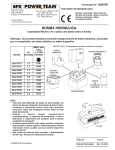
LOWER RING-GEAR BOLTS AND LOCKSTRIPS:
TYPICAL INSTALLATION
\
• •
-
-
/
-
Lockstrip
/ 7
/11-i:`
A
21101P10111111111MIKMAWIr
1. Install lockstrips as shown.
• Use Kit #58004 for Condor Models 76, 68, 58, 56, 50,
6066, 5056, 4248.
• Use Kit #58005 for Condor Models 60N, 46N, 36N,
4046N.
• Use Kit #58006 for Condor Models 48, 4046, 3036N.
2. Bolts are special (grade, strength & length) for the
Condor machines. DO NOT USE ANY OTHER BOLTS.
3. Do not use lockwashers.
4. Torque lower ring-gear bolts to 105 ft-#s ± 5 ft-#s,
using conventional criss-cross torque sequence.
5. Bend-up ears (ends of lockstrips) on flat of bolt hex head
as shown. Bend two places for each lockstrip.
Note: BE CERTAIN THE LOWER RING-GEAR BOLTS ARE CHECKED DURING THE NORMAL
INSPECTION/SERVICING, AFTER EVERY 50-HOUR OPERATION OF YOUR CONDOR
MACHINE(S).
II
CHL AVA R
CORPORATION
LOWER RING GEAR-BOLTS & LOCKSTRIPS:
BILL OF MATERIAL
1. Kit #58004 for Condor Models 76, 68, 58, 56, 50, 6066, 5056, 4248,
and 3238.
Consists of:
2.
•
Lockstrip
Calavar Part #68237; Qty = 9
•
Special Hex Head Capscrews; 1/2-13 UNC x 1-3/4 long
Calavar Part #BOW36107; Qty - 18
Kit #58005 for Condor Models 60N, 46N, 36N, and 4046N.
Consists of:
3.
•
Lockstrip
Calavar Part #68226; Qty = 9
•
Special Hex Head Capscrews; 1/2-13 UNC x 2-3/4 long
Calavar Part #BOW36111; Qty = 18
Kit #58006 for Condor Models 48, 4046, and 3036N.
Consists of:
Lockstrip
Calavar Part #68226; Qty = 9
Special Hex Head Capscrews; 1/2-13 UNC x 1-3/4 long
Calavar Part #BOW36107; Qty = 18
Note:
Bolts are special (grade, strength and length) for the
Condor machines. Use only Calavar supplied bolts in the
above kits. DO NOT USE ANY OTHER BOLTS.
SELF-PROPELLED CONDOR
SPARE PARTS LIST
Stock will vary depending on units in inventory and type of use.
80305
Switch
80058
Switch
80026
Switch
80372
Switch
80306
Switch
Limit Switch
80043
Key Switch
80023
Latching Relay
80024
Relay
E3OJT
Stop, Start Switch
80025
Circuit Breaker
80378
Rheostat
WISCONSIN ENGINE PARTS
VJ-68
Rectifier Module
VJ-59
Regulator Module
KJ-16J
Champion Spark Plug
1GS-2224LB
Point Set
1BB-204255
Condensor
HONEYWELL PARTS
Controller
BERTEA PARTS
2 34912
Pilot Valve
HYDRAULIC SPARE PARTS
S-29
.
Oil Filter (System Return)
C-68
Oil Filter (Control Pressure)
RU-4o-s4
Oil Filter (Engine)
Series VIII
SPC9-81
1 6.
INTERVAL SYMBOL
0
A
I
LUBRICANT
SEMI-MONTHLY
CG - CHASSIS GREASE
MONTHLY
EO - ENGINE OIL
or
I 4100MONTHS
HOURS
0 ANNUALLY
CG-.SHELL DARNA AX70330 or
EQUIVALENT
EO- S.A.E. 30 WEIGHT
GO - SAE 90 WEIGHT EP•
SL- CROWN 7045 HEAVY
DUTY OPEN GEAR AND
WIRE ROPE LUBE OR
EQUIVALENT
(50 )SHEAVE PIN
AIR
CLEANER
OIL BATH
GO - GEAR OIL
e
SL - SPRAY LUBE
NOTE:
* WARNING LUBRICANT
MUST UM CONTAIN
LITHIUM
.
CRANK
CASE
DRAIN
CRANK
CASE FILL
OIL FILTER
CHANGE
v SPEED
G TORQUE HUB
REDUCER
TIE RODS
(Two Places
Each Side)
STEERING KNUCKLE
(Two Places each side)
RING GEAR
(4 Places)
ROTATE WHILE LUBING
RE-PACK WHEEL
BEARINGS
(Wheel Bearing Grease)
S E LF-PROPE L LEDCON DOR LU BRI CA TION C HA RT
TYPE OF LUBRICANT
BEARINGS (BothSides
INTERMEDIATE (50)
BOOM CABLE SHEAVE
(One place underneath)
PLATFORM LEVELING
SLAVE CYLINDER
( CflePlace)
58, 68 Side
(Two Places)
MASTER LEVELING CYLINDER
(Two Places)
INTERMEDIATE BOOM
CABLE SHEAVES (50)
58, 68 Both Sides
TOPPING CYLINDER
(Two Places)
DIP STICKS
HYDRAULIC TANK OIL
(ATF DEXRON II)
HYDRAULIC TANK FILTER
CHANGE
STEERING CYLINDER
PIVOT POINTS
(Both Sides)
SE LF- P RO PE L LE D CON D ORLU BRI CA TION C HA RT
STEERING
CYLINDER PIN
Lubrication
Type — EP 90
Oil Temperature
• Continuous — 160°F
• Intermittent — 200°F
Oil Change
• Initial — After 50 hours of operation
• Subsequent — 1000 hours or one year which ever comes first
Oil Fill Level
• Unit mounted horizontal — half-full
Series VIII
SPC9-81
19.
LUBRICATION
LUBRI CATI ON
Refer to Self-Propelled Condor Lubrication Chart for location of items
requiring lubrication and service. Recommended lubricating intervals
are based on normal use in normal environmental conditions. User is
cautioned to adjust the lubricating interval accordingly to meet each
individual condition and usage.
Specific lubricants as recommended by the component manufacturers are
generally the best choice. Should their lubricant not be available in
your area, consult your local supplier for an equivalent. Under no
circumstances should lubricant containing "LITHIUM" be used.
1. PRESSURE GUN LUBE POINTS
Lubricant
Chassis Grease
Shell Darna AX70330 or equal
Time Interval
50 Hours of Operation
Procedure
Service all fittings as indicated in
chart. Clean lube fitting and apply
pressure gun. Wipe away all excess lubricant from exposed surfaces. Over lubrication can collect dirt and foreign matter
which acts as an abrasive.
When lubricating turret rotation bearing,
it is recommended that turret be rotated.
2. AIR CLEANER (OIL BATH)
Lubricant
Time Interval
Procedure
3. STEERING CYLINDER PIVOT POINTS
Lubricant
Time Interval
Procedure
S.A.E. 30 weight engine oil
50 Hours of operation
Remove oil cup from bottom of
air cleaner and clean thoroughly.
Fill to level line indicated on
the oil cup.
S.A.E. 30 weight engine oil
50 Hours of operation
Apply with oil can to both sides
of pivot.
LUBRICATION (Continued)
4.
ROTATION GEAR TEETH & PINION
Lubricant
Crown 7045 heavy duty open gear
oil or equal.
Time Interval
500 Hours of operation, or yearly
whichever comes first.
Procedure
Wipe clean gear teeth on rotation
ring and pinion. Spray on lubricant.
5. ROTATION GEAR BOX
Lubricant
Time Interval
Procedure
6. DRIVE TORQUE HUBS
Lubricant
Time Interval
Procedure
S.A.E. 90 weight EP oil
Check every 50 hours. Change every 500
hours of operation or yearly, whichever
comes first.
Remove drain plug on side. Refill until
lever reaches about 1 in. from top of fill.
S.A.E. 90 weight EP oil
Check periodically & fill as
required. Change every 500 hours, or
yearly, whichever comes first.
To check level, rotate wheel so
that level plug is horizontal.
Remove plug if steady flow of oil
runs out, unit is sufficiently full.
To add oil, remove fill plug on top
of gear hub and level plug (horizontally). Fill until oil runs out of
level plug.
7.
WHEEL BEARINGS
Lubricant
Time Interval
Procedure
8.
HYDRAULIC SYSTEM
A. Fluid Level
Wheel-bearing grease
500 Hours or yearly, whichever comes first
or upon reassembly
Remove hub cap, clean out old lubricant
and repack.
Check level daily. Maintain fluid level
at full mark or dipstick with the boom
fully retracted and in stowed position.
B. Hydraulic Oil Filter
Replace filter element every 100 hours of
operation.
C. Procedure
Unscrew element and replace with new
element.
8.
HYDRAULIC SYSTEM (Continued)
C. Tank Breather
Procedure
D. Hydraulic Tank
Procedure
Clean every 50 hours of operation
Remove from tank and clean with solvent,
air blow dry
Change every 500 hours or yearly, whichever comes first. Drain oil from tank
and replace filter element. Add oil to
tank required level.
Use only ATF Dexron II or equal. Do not
mix hydraulic oil.
9.
ENGINE
Refer to engine manufacturer's recommended maintenance and service procedure for lubricant and time interval.
HYDRAULIC
OIL SPECIFICATIONS
for
CALAVAR AERIAL WORK PLATFORMS
OIL COMPANY
BRAND NAME
GULF
CHEVRON
ATF
Dexron II
ATF
Dextronll
D Series
SHELL
UNION
MOBIL
Donax
ATF
Dexron
ATF
220
CONOCO
Dexron
II
VISCOSITY, SUS @ 100° F
SUS @ 210° F
205
50.1
195
50.4
175
49
200
52.3
187
50
170
50
VISCOSITY INDEX TYPICAL
150
155
160
172
159
145
FLASH POINT 0 F
350°
405°
390°
395 °
320°
365°
POUR POINT 0 F
-45°
-50°
-45°
-45°
-50°
-45°
.
.
Series VIII
SPC9-81
20.
TROUBLESHOOTING GUIDE
In the following section are possible problems and their solutions. This section
will save down time and provide a starting point for the mechanic to troubleshoot
and isolate the cause for malfunction.
PART 1 - WISCONSIN
1.
ENGINE WILL NOT START (will not turn over)
A.
B.
C.
D.
E.
2.
ENGINE
Check
Check
Check
Check
Check
battery and connection
starter solenoid
master switch
latching relay
starter
ENGINE WILL NOT RUN (engine turns over)
A.
B.
C.
D.
E.
Check
Check
Check
Check
Check
gas
ignition coil and points
fuel pump and fuel line
choke and air cleaner
fuel filter
ENGINE WILL NOT START - LP GAS
A.
B.
C.
D.
E.
4.
LOSS OF POWER (engine)
A.
B.
C.
D.
5.
L.P. bottle opened too fast
Fuel line connection to bottle loose
Fuel flow to carburetor (lock off filter & vacuum switches)
Fuel storage tank empty
Regulator or carburetor
Timing
Governor setting (refer to Wisconsin Engine Manual)
Engine RPM too low
Wrong fuel (regular gasoline only)
UNIT WILL NOT START (electrical)
A.
B.
C.
D.
Battery dead
Battery connection
Solenoid bad
Check battery alternator
Series VIII
SPC9-81
21.
PART II - ELECTRICAL
1.
BATTERY DEAD
A.
B.
C.
Master switch left on with start circuit energized
Alternator inoperative (regulator or rectifier module)
Battery not to full charge
a.
b.
2.
FUNCTION INOPERATIVE FROM GROUND AND AERIAL
A.
B.
C.
D.
3.
Refer to Item 2 above
Check coil on solenoid valve
Refer to Items 2 and 3
Check toggle. switch
NO HYDRAULIC PRESSURE (Engine running, no high RPM)
A.
B.
C.
6.
controller and toggle switch
wiring for continuity
pilot valves
for voltage into circuit
FUNCTION INOPERATIVE (Solenoid valve assembly)
A.
B.
C.
5.
Check
Check
Check
Check
FUNCTION INOPERATIVE FROM EITHER GROUND OR AERIAL (Bertea)
A.
4.
Dead battery
Condor battery used to jump start other equipment
Check circuit to pump solenoid
Check coil on pump solenoid (magnetic field if energized)
Open hydraulic tank gate valve
FUNCTION WILL CREEP WHEN NOT IN USE (Pump on stroke, high engine RPM)
A.
B.
C.
Check controller for null
Check for voltage crossing over into another circuit
Air in end cap
PART III - HYDRAULIC
1.
FUNCTION INOPERATIVE (Engine running high rpm, hydraulic pressure at
2100 or 2200 psi)
A.
B.
C.
2.
Check for control pressure
Check for plugged control pressure oil filter
Check in-line filter into main valve
NO CONTROL PRESSURE
A.
Flow control valve (replace)
Series VIII
SPC9-81
22.
3.
LOW OR NO HYDRAULIC PRESSURE
A.
B.
C.
Refer to Item 5 - Electrical
Check compensator on John Deere Pump (set too low)
Check oil tank gate valve
PART IV - DRIVE
1.
LOSS OF DRIVE POWER
A.
B.
C.
D.
E.
F.
2.
Pump pressure set too low
Driving unit in high gear
Engine rpm too low
Flow divider valve
Posi-Traction Valve (open)
Bad drive motor
UNIT WILL NOT MOVE FORWARD OR REVERSE
A.
B.
Check torque hub (may be
Refer to Item 2 - Electrical Section
UNIT WILL NOT SHIFT TO LOW OR HIGH (Model
A.
B.
C.
4.
68 only)
Check limit switch (boom elevation and extension)
Check two speed toggle switch and wiring
Check hydraulic tow-speed solenoid valve (Hydraulic Panel, Figure 11,
Item 123.)
NO STEERING
A.
B.
C.
D.
Needle valve controlling oil flow to solenoid valve bank
Check toggle switch and wiring
Check coil on Racine Valve
Damaged steering cylinder, or broken hydraulic line
NOTE: Above would apply to Platform Rotation and Tilt
5.
BRAKES APPLY TOO FAST
A.
B.
6.
Alter brake adjustment valve (close slightly and reseal)
"0" Ring on brake release piston damaged (W.S.I.)
BRAKES APPLY TOO SOON
A.
Alter brake adjustment valve (open slightly and reseal)
Series VIII
SPC9-81
23.
PART V - BOOM OPERATION
1.
NO LIFTING POWER
A.
B.
2.
BOOM BLEEDS DOWN
A.
B.
C.
3.
Check emergency bleed down valve (may be open)
Holding valve topping cylinder
Internal leak (cylinder)
BOOM RETRACTS (bleeds in or out)
A.
B.
4.
Internal leak (cylinder)
Check system hydraulic pressure. Refer to specification page
for applicable unit
Check holding valve
Inernal leak (cylinder)
ELECTRICAL CABLE MOVING IN AND OUT WITH BOOM (at platform): MODEL 50 ONLY
A.
B.
Check electrical cable adjustment. NOTE: This adjustment can be
seen on bottom of boom at turn-around bracket cover, and should be
1-1/8" from spring end to housing.
Boom mechanical cables loose (re-torque to 60 ft. lbs.)
EXCESSIVE BOOM PLAY
A.
Missing or worn wear pads
PART VI - TURRET
1.
EXCESSIVE TURRET ROTATION BACKLASH (turret rotation)
A.
B.
C.
2.
Check rotation gear box (loose)
Check brake in gear box (tighten)
Check ring gear bolts for torque (140 ft. lbs. turret, 80 ft. lbs. base)
BROKEN PIN RETAINERS BOTH TURRET AND BOOM
A.
Lack of lubrication
Series VIII
SPC9-81
24.
PREVENTIVE MAINTENANCE
This section is devoted strictly to preventive maintenance. By using the Condor
Installation Inspection Report as a guideline, the owner has a starting point
from which a successful preventive maintenance program can begin.
Located under "Lubrication" in the Calavar Section of the Parts Manual is the
Lubrication Chart showing the location of all the lube points. The specifications
for lubrication and general inspection referred to in this section may have to be
changed due to the application or environmental conditions the Condor is subjected
to. For example: The air cleaner may have to be checked and serviced more frequently when the Condor is used in a sandblast operation than would normally be
done if the unit was being used for assembly of fire sprinkler systems.
The following items should be checked and followed depending on the type of use
to ensure the unit is in top mechanical condition.
A.
GENERAL APPEARANCE
1.
2.
3.
4.
5.
6.
7.
8.
9.
10.
11.
12.
13.
14.
15.
B.
SEMI-MONTHLY
1.
2.
C.
Clean unit (free of oil and dirt)
Operation and safety decals in place and legible
Tire pressure - see stencil on carriage
Tire condition (free of serious cuts or defects)
Proper engine oil level
Proper hydraulic oil level
Air cleaner oil level
Battery electrolyte level
Battery fully charged
Fuel level
Check and lube, if necessary (check lube chart for locations)
Check ring gear bolts for proper torque, 140 top, 80 bottom with
Nordic lockwasher
Proper engine rpm
Proper brake operation
Hour meter reading
Check and lube, if necessary
Check battery electrolyte level
.
MONTHLY, OR FIRST 50 HOURS
1.
2.
3.
4.
5.
6.
7.
Series VIII
SPC9-81
Check and lube, if necessary
Check condition of battery
Check air cleaner
Change engine oil filter
Change hydraulic return oil filter
Check boom cables for torque
Check ring gear bolt for torque
2 5.
D.
SIX MONTHS, OR 100 HOURS
1.
2.
3.
4.
5.
6.
E.
Check and lube, if necessary
Change control pressure oil filter
Change engine oil filter
Change hydraulic return oil filter
Check ring gear bolts for torque
Safety inspection (return form to Calavar)
ANNUALLY
1.
2.
3.
4.
5.
6.
7.
Series VIII
SPC9-81
Repack all wheel bearings
Check oil level---speed reducer, turret rotation
Change hydraulic oil (if unit has been used in sandblast
operation regularly)
Check torque hub oil level
Check condition of boom cables
Safety inspection
Refer to lubrication chart
26.
CONDOR OPERATION AND SAFETY MANUAL
It shall be the responsibility of all users to read and comply with the
following common sense rules that are designed to promote safety and aid in
better understanding the operation of the Self-Propelled Condor. These rules
do not purport to be all inclusive, nor to supplant or replace other additional
safety and precautionary measures to cover usual or unusual conditions. If
these rules conflict in any way with any state, local or federal statute or
regulations, said statute or regulation shall supersede these rules and it shall
be the responsibility of each user to comply therewith.
UNLOADING:
1.
If the use of loading ramp is necessary to unload the Condor, select a
sturdy ramp. The Condor Model 50 weighs approximately 15,000 lbs._ and the
Condor Models 58, 68 weigh approximately 23,000 lbs.
2.
If the work platform was removed for shipment, it must be replaced prior
to unloading.
OPERATING:
1.
Operating instructions are located on a placard on the ground control side
of counterweight. Before operating unit, checkout items aa instructed
on the placard and in this booklet.
2.
Start unit and allow engine to warm up. If it is necessary to reposition
boom, this can be done from the ground control station. Switch Aerial /
Ground Selector Switch to Ground, and by activating toggle switches, the
boom can be placed in a position that would be safe for unloading. If
possible unload the Condor boom-first.
3.
By switching Aerial/Ground Selector Switch to the Aerial Position, ground
position controls are inoperative. Unit can now be operated from Aerial
Position.
4.
Aerial controllers are proportional, except for steering, platform tilt
and platform rotation, which are bi-directional toggle switches. Each
controller has a deadman lock-out mechanism that must be lifted before
the controller can be activated. By lifting the deadman button not
only is the controller free to be activated, but also will bring the
pump from a stand-by position to a working position, while increasing
engine rpm from idle to operating rpm.
5.
Normal driving position for the Condor is with the counterweight over the
driving wheels. Controller movement is based on this configuration. With
counterweight over steering, the drive and steering control will react
reversed.
Series VIII
SPC9-81
a.
6.
Try each controller momentarily to orient yourself on its operation. The
controller should always be moved gradually to obtain the smoothest
possible operation.
7.
Before unloading Condor, test the automatic braking system by moving forward and reverse to see that the brakes apply when the drive controller
returns to the neutral position.
8.
Located between the drive motors is the two speed valve. Handle up
indicates high speed, minimum torque. Handle down indicates minimum
speed, maximum torque. Unit should be loaded and unloaded •in low--handle down.
INSPECTION:
1.
Once unit has been unloaded, give the unit a visual inspection paying
special attention to items listed below. This inspection should become
part of a daily inspection performed at the beginning of a work shift by
the assigned operator.
A
B
C
D
E
F
G
H
I
Check tire pressure
Check for cut or damaged tire
Check electrolyte level
Check engine oil
Check hydraulic oil level (use A.T.F. oil only)
Check oil cooler for damage and cleanliness
Check air cleaner oil level and cleanliness
Check stop and start circuit from ground and aerial position
Visual inspection for hydraulic leaks
NOTE: Condor models equipped with 54:1 torque hubs. Check operation
of slope sensor device. If possible, place unit on slope of 5 °
or more, indicator light should come on and all boom functions
will be inoperative.
The Condor Models are also equipped with limit switches. One located
inside the boom and another located outside of boom at the boom to
turret hinge pin. When either switch is activated, they automatically
shift drive to low speed when boom is extended or raised to horizont -al.
OPERATOR TRAINING:
1.
In order for an operator to thoroughly understand the operation of a
Condor and to become a qualified operator, it is recommended that after
having been checked out by a trained, qualified operator, the trainee
operator should move the unit to an area free of any overhead obstruction.
The surface upon which the unit will be operated should be level with no
hazardous irregularities or accumulation of debris.
Series VIII
SPECS-81
b.
2.
Condors are equipped with automatic shift to low for the drive function.
This is done automatically when boom is extended or reaches horizontal.
3.
Elevate boom to approximately 60 ° , at this angle the operator will have
a clear field of vision over the area below. Repeat low speed driving
exercise.
4.
With boom at 60 ° , extend boom approximately half way and repeat driving
exercise.
5.
With boom at 60 ° and half extension, rotate counterweight between drive
wheels and repeat driving unit.
6.
Extend boom to maximum and raise boom to 75 ° , rotate turret. Turret
rotation is continuous. By gradually operating rotation controller
giving full signal to rotation, and by gradually returning controller
to neutral, the operator will learn how the rotation can be controlled
to place unit along side a building smoothly.
Place counterweight over drive wheels, with unit at
extension. Repeat driving exercise.
75°
and maximum
NOTE: Extreme care must be taken when driving in this position, as
ground vision has been reduced. The operator must watch for
objects or personnel that may be in the area.
8.
At the end of this exercise, the operator will have driven the Condor in
both high speed and low speed; with extended and retracted boom; and will
have driven the Condor with boom off to the side, and will have practiced
placing Condor in imaginary work positions.
SAFETY:
Listed below are items pertaining to safety that the operator must know and follow.
1.
The Calavar Self-Propelled Condor is a personnel lifting device and it
is essential that it is properly maintained and operated to perform all
functions with maximum safety and efficiency.
2.
The operation of any new and unfamiliar equipment can be hazardous in the
hands of untrained operators. Only trained operators should be assigned
to operate the Condor.
3.
It is the responsibility of the operator to be familiar with the manufacturer's manual and to follow all recommendations made. Never exceed
manufacturer's recommended load.
4.
It is the responsibility of the owner to instruct the operator with the
safety requirements made not only by Calavar, but by various safety
boards in your area, as well as requirements set down by OSHA and ANSI.
(Note: See ANSI A92.5-1980.)
Series VIII
SPECS-81
c
.
5.
Do not operate Condor in excess of rated load specification.
6.
The Condor is a non-insulated unit and must not be operated near high
voltage lines.
7.
Do not lean over platform railings to perform work.
8.
Do not use ladder or makeshift devices on the platform to obtain
greater heights.
9.
Care must be taken to prevent raising or lowering boom into objects.
10.
The platform capacity must be derated for all tools, accessories and
operators.
11.
Always distribute load evenly over work platform.
12.
The Condor is equipped with Safety "D" Rings. A body belt must be worn
with a safety strap attached.
13.
Safety head gear should be worn by personnel in work platform.
14.
Care must be taken in storing loose material in work platform such as
pipe, rope, wire and miscellaneous boxes. If it is necessary to store
such items in platform, they must be stored in such a way as to prevent
walking or tripping over such items.
15.
Do not alter equipment.
16.
Do not override safety devices.
17.
Slope control devices should be checked periodically for proper operation.
Immediate repairs are mandatory on this device should it be found inoperative or disconnected.
18.
Extremely uneven, sloping, or pft terrain is hazardous and must be avoided.
The Condor must not be operated on terrain with more than a 5 ° slope.
19.
The Condor boom is not be be used to push unit along ground.
20.
The Condor boom is not to be used to lift wheels off ground.
21.
Visual inspection of turret rotation ring gear bolts in turret and inside
base assembly must be accomplished periodically and if found loose, retorqued to 80 ft. lbs. on base bolts and 140 ft. lbs. on turret bolts.
22.
Visually inspect tires. Tires that have been severly cut to the cord are
dangerous and should be replaced. Recommended tire pressure must not be
over inflated.
(See Section One, Page 27.)
Series VIII
SPEC9-81
d.
23.
Visual inspection of inner boom extension/retraction cables must be
accomplished periodically to determine any damage. Damaged cables
must be replaced immediately. Failure to do so will result in a
dangerous condition to both operator and equipment.
24.
Under no circumstances shou ld horseplay be tolerated. Report any
foolishness or misuse of equipment to proper personnel.
25.
Never take chances. Do not work on platform if your physical condition
is such that you feel dizzy or unsteady in any way.
26.
ground for welding. Disconnect both
The Condor is not to be used
positive and negative grouhd leads from battery before welding on Condor.
Series VIII
SPC9-81
e.
IM
AILIWAIR
CORPORATION
PREVENTATIVE MAINTENANCE
SELF-PROPELLED AERIAL WORK PLATFORMS
GENERAL
The finest equipment manufacturered is only as good as it is maintained.
Many times costly repairs and loss of revenue can be avoided by planning
ahead, setting a regular schedule and performing preventative maintenance.
You can do preventative maintenance NOW or costly repairs LATER.
This section is devoted to the PREVENTATIVE MAINTENANCE PROGRAM of the
CONDOR and is broken down into two (2) phases; an INSPECTION maintenance
and LUBRICATION maintenance. A lubrication chart and a complete preventative maintenance interval check list is provided.
The preventative INSPECTION maintenance is generally, but not limited to,
the responsibility of the operator. It is to his best interest that the
inspection maintenance be carried out as it directly effects his safety. The
preventative LUBRICATION maintenance is the responsibility of the serviceman
or mechanic as in some instances shop time will be required to perform the
maintenance tasks.
Many of the suggestions for preventative maintenance described and noted
herein may sound time consuming and expensive. This is not the case. The
program has been carefully layed out and if closely followed, it will result
in an extended life expectancy of the unit as well as the reduction in downtime and costly repairs.
The inspections and checks listed are not intended to replace any local or
regional regulations which may pertain to this type of equipment, nor should
the list and schedule be considered all inclusive. Variances in interval
times may occur due to climate and/or conditions depending on the location and
use of the machine.
Always insure that applicable safety precautions are strictly observed when
performing the maintenance inspections and checks. Make certain that damaged
components or those in need of adjustment, repair or replacement are corrected
before operation.
PREVENTATIVE INSPECTION MAINTENANCE
This field inspection list provides for a systematic inspection of
the CONDOR. The items listed to be inspected or checked daily will basically
insure a good safe unit performance prior to start-up work operation. By
accomplishing these inspections on a daily basis any potential malfunction
will be identified and detected before it results in a major problem. The
fifty (50) hour inspection will detect any defective, damaged or improperly
secured part.
The 50-hour time interval is for normal operation. Should the unit be
subjected to extensive use or if the application involves operation in abnormal environmental conditions, then the inspections should be made more often.
It is suggested that a maintenance log be kept and any conditions or
items found to be abnormal should be recorded.
DAILY INSPECTION MAINTENANCE
A.
VISUAL
1. Overall Condition
Inspect platform, boom, turret and
carriage that no physical damage is
evident. Look for missing components,
loose parts, etc.
2. Tire Condition
Inspect tires for wear, cuts and
proper pressure (pneumatic filled only)
3. Battery Cable Connections
Inspect for looseness and corrosion
of terminals.
4. Hydraulic Fluid Leaks
Inspect that there is no evidence of
fittings or hoses leaking.
5. Main Electrical Connections
Inspect harness connections at rear of
ground box and at platform console to
assure they are tight.
B.
FLUID LEVEL CHECK
1.
Engine Oil Level
If low, add as recommended by engine
manufacturer in quantity as required.
B.
C.
FLUID LEVEL CHECK (Continued)
2. Engine Coolant Level
Add as required (water cooled engine only)
3. Fuel Tank Level
Check level
4. Hydraulic Tank Level
If low, add ATF Dexron II as required.
5. Battery Electrolyte Level
Add as required.
OPERATIONAL TEST
NOTE:
1.
Instrument Check
A.
2.
3.
Start engine and follow all instructions and procedures.
Be observant of all instruments and controls for proper
operation as well as each function of the unit. Pay
particular attention to any unusual noises or jerky operation.
Hourmeter
Is it recording properly?
B. Ammeter
Is battery being charged?
C. Oil Pressure Gauge
(Diesel Engine) Is pressure indicating?
Ground Control Console Operation Check
A. Toggle Switches
With engine off, check that all
momentary switches return to neutral
when actuated and released.
B. Boom Functions
Start engine and operate functions
through one complete cycle.
C. Emergency Controls
Stop engine and operate emergency controls.
Platform Control Console Operation Check
A. Toggle Switches
With engine off, check that all momentary switches return to neutral when
actuated and released.
B. Controllers
Check that lever cannot be moved without
pulling knob. Check that lever returns
to center position when actuated & released.
C. Boom Functions
Start engine and operate all aerial functions one complete cycle.
D.
Operate drive and steering functions and
check braking.
Drive Functions
E. Emergency Controls
Stop engine and operate emergency controls.
F. Slope Sensor
For procedure, refer to vendor data in
operation manual, Honeywell Section.
PREVENTATIVE MAINTENANCE INSPECTION
EVERY FIFTY (50) HOURS OF OPERATION
A.
B.
CARRIAGE
1. Visual Damage
Inspect for weld cracks, dents, or bends.
2. Steering Cylinder
Check cylinder and pins holding cylinder
in place for proper installtion.
3. Steering Tie Rods
Check pin installations and connections
for loose, binding, worn or missing parts.
4. Steering Yokes
Check installation, pins, caps, and
steering stop.
5. Wheels
Check for loose or missing lug nuts, loose
or worn spindle, damaged or cracked rims.
6. Torque Hubs & Motors
Check hub and motor connector and disc
brake for leakage.
7. Hydraulic Fittings
Check for leaks and tightness
8. Hydraulic Hoses
Check for leaks, cuts, abrasions
9. Tire Pressure
(Pneumatic filled) Check for proper pressure.
10. Tire Damge
Check for wear & cuts
11. Rotation Gear
Check bolts securing ring gear to chassis for
tightness and that all lock tabs are in place.
TURRET
1. Visible Damage
Inspect for weld cracks, dents or bends
2. Rotation Gear
Check bolts securing gear to turret for
tightness.
3. Rotation Gear Box
Check oil level. Check mounting bolts.
Inspect motor and coupling and pinion
installation.
4. Rotary Coupling
Inspect for leakage and check mounting
bolts and bracket.
5. Hydraulic Valves
Check mounting bolts and inspect for
damage or leakage.
6. Hydraulic Hoses
Check for leaks, cuts, abrasions
7. Hydraulic Fittings
Check for leaks and tightness
8. Electrical Wiring
Inspect for fraying cracked insulation
9. Electrical Connections
Check for corrosion, looseness and insure
good contact.
B.
C.
TURRET (Continued)
10. Lift Cylinder
Inspect for damage and leakage . Check
pin installation and retainers
11. Master Leveling Cylinder
Inspect for damage and leakage . Check
pin installation and retainers
12. Counterweight
Check mounting bolts for tightness.
13. Shrouding, Covers
Check for loose, damaged or missing parts
and fasteners.
MAIN POWER SOURCE
1. Engine
See engine manufacturer's "Operation &
Maintneance Manual" for maintenance check
list (Wisconsin, Deutz, Ford).
2. Air Cleaner
Check oil level, mounting and connection.
3. Muffler
Check shrouding, connection and mounting.
4. Exhaust Tube
Check for rust, leaks and installation.
5. Engine Mounts
Check bolts for tightness.
6. Throttle Solenoid and Linkage Check mounting, operation and connecting parts.
7. Fuel System
Check tank, mounting, fuel line and connections.
0.
8. Battery
Check electrolyte level, mounting and hold
down.
9. Battery Cables
Check connections for tightness, corrosion
and frayed insulation.
10. Hydraulic Pump
Inspect pump for damage, check mounting
bolts and connection to engine.
11. Emergency Motor/Pump
Inspect pump and motor for damage. Check
mounting bolts & electrical connection.
12. Hydraulic Hoses
Check for leaks, cuts and abrasions.
13. Electrical Wiring
Inspect for fraying, cracked insulation.
14. Electrical Connections
Check for corrosion, looseness and insure
good contact.
BOOM ASSEMBLY
1. Visible Damage
Inspect for weld cracks, dents or bends.
2. Pivot Pin
Check pin installation and retainer.
3. Extension Cylinder
Inspect for damage & leakage. Check pin
installation & retainer.
D. BOOM ASSEMBLY (Continued)
E.
4. Hose & Cable Routing
Check routing of hydraulic hose & electrical
cable from turret to boom. Inspect for
chafing, broken tyes or overly tight routing.
5. Mechanical Cables
(3-Section Boom)
Inspect cables for fraying or damage and
tightness (torque). Inspect for proper
installation on sheave.
6. Wear Pads
Inspect for clearance, excessive wear.
Check mounting bolts and adjustment.
7. Slave Leveling Cylinder
Inspect for damage and leakage. Check pin
installation and retainer.
8. Tie Down Ring
Check for tightness.
9. Limit Switches
Inspect for damage. Check electrical
connection.
PLATFORM AND SKIRT
1. Visible Damage
Inspect for weld cracks, dents or bends.
2. Platform Mount
Check platform to skirt mounting bolts
for tightness.
3. Hydraulic Hose & Electrical
Cable Routing
Check routing from boom to skirt. Inspect
for chafing broken tyes or overly tight
routing.
4. Platform Slide Bar
Check that it slides freely.
ON UNITS EQUIPPED WITH OPTIONAL 180° PLATFORM ROTATION-5. Rotary Actuator
F.
Inspect for damage, leaks and mounting
bolts for tightness. Check hydraulic hoses
for cuts and abrasions.
GROUND CONTROL CONSOLE
1. Visible Damage
Inspect for weld cracks, dents or bends.
2. Mounting
Check that bolts are secure.
3. External Electrical Connection Insure connection is firmly made.
4. Instruments
Inspect for damage.
5. Internal Wiring
Inspect for fraying broken insulation.
Check that connections are tight.
6. Slope Sensor
Inspect for damage and check mounting
bolts for tightness.
7. Enclosure
Check for any moisture, inspect cover seal.
Insure cover is firmly secure.
F.
G.
GROUND CONTROL PANEL (Continued)
8.
Toggle Switches
Check that momentary type return to center
position when actuated and released.
9.
Speed Control
Insure knob is firmly secured to shaft.
Check that speed control rotates freely.
PLATFORM CONTROL CONSOLE
Inspect for dents, etc.
1. Visible Damage
2.
Check that bolts are secure and tight.
Mounting
3. External Electrical Connection Insure connections are firm.
4.
Controllers
A. Check mounting screws for tightness.
B. Check that handle cannot be moved without
first lifting on knob.
C.
Inspect rubber bellows for damage.
D. Check that handle returns to center when
actuated and released.
H.
5.
Toggle Switches
Check that momentary switches return to
center position when actuated & released.
6.
Engine Stop-Start
Check that switch when actuated stays in
"ON" or "OFF" position.
7.
Electrical 110-V Receptacle
Inspect for damage.
OPERATIONAL SYSTEM
1. Operation with ground panel controls
A. Start engine and listen andior observe:
1. Unusual noise from engine or pump.
2. Excessive engine vibration.
3. Operation of hourmeter and ammeter.
B. Actuate boom "raise" control switch and observe:
1. Increase in engine RPM (gasoline engines)
2. Boom raises smoothly.
3. Hydraulic hoses & electrical cable at rear of boom are
properly moving.
4. Proper platform leveling.
5. At full travel release control, switch returns to center.
6.
Inspect lift cylinder rod for damage to chrome.
7. Platform stays elevated, is not lowering under its own power.
H.
OPERATIONAL SYSTEM (Continued)
8. With speed control in "slow" actuate boom "lower". Rotate
speed control slowly to "fast" and observe change in speed.
C. With boom horizontal, actuate boom "EXTEND" and observe:
1. Any unusual noise in telescoping
2. Boom telescopes smoothly
3. At full extension, release control, switch returns to center
.
4. Visually inspect inner boom sections for weld cracks, dents
or scouring.
D. Actuate boom rotate control and observe:
1. Any unusual noise during rotation
2. Release control, switch returns to center
E. Actuate emergency power switch (engine OFF) and any of the boom
function controls, observe:
1. Any unusual noise
2. Function operates normally
2. Place speed selector switch in "FAST". Actuate drive controller and
observe:
A. Travel starts smoothly and stops smoothly when control is released.
B. Travel speed is in high range.
3. With speed selector in "FAST" actuate boom extension and drive
controller travel speed should automatically switch to slow range.
Retract boom.
4. With speed selector in "FAST" actuate boom "Raise" until above horizontal
and actuate drive controller. Travel speed should automatically switch
to slow range.
5. Actuate steering control right and left, observe:
A. Steering wheels turn smoothly
B. Steering continues until stops are reached.
AV A R
CORPORATION
PREVENTATIVE MAINTENANCE INTERVAL CHECK LIST
--Operational Hours Or Yearly, Whichever Comes First-ITEM REQUIRING ATTENTION
DAILY
50
100
HOURS HOURS
500
HOURS
1, 000
HOURS
YEARLY
A) Carriage Assembly
1 - Visible Damage--Weld Cracks, Dents
X
2 - Steering Cylinder and Pins
X
3 - Steering Tie Rods and Connections
X
4 - Steering Yokes
X
5 - Lubricate Steering Points
X
6 - Repack Wheel Bearings
7 - Visually Inspect Torque Hubs, Motors
X
8 - Check Torque Hub Oil Level
X
9 - Change Torque Hub Oil
10- Inspect Wheel Mtg., Lugs, Rims
11- Inspect Tires for Cuts and Damages
X
X
X
X
X
X
X
X
12- Check Tire Pressure (Pneumatic)
X
13- Check Hydraulic Fittings and Hoses
X
14- Check Rotation Gear Bolts
X
B) Turret Assembly
1 - Visible Damage--Weld Cracks, Dents
X
2 - Check Rotation Gear Bolts
X
3 - Check Rotary Coupling Mounting Bolts
X
4 - Check Rotation Gear Box Mounting
X
5 - Check Rotation Gear Box Oil Level
X
6 - Change Rotation Gear Box Oil
7 - Check Rotation Drive Motor and Pinion
X
8 - Check Hydraulic Valve Mounting
X
9 - Check Hydraulic Hoses and Fittings
X
10- Check Wiring and Electrical Connections
X
11- Inspect Lift Cylinder
X
12- Inspect Lift Cylinder Pins
X
13- Inspect Master Level Cylinder
X
14- Lubricate Lift and Level Cylinder Pins
X
15- Check Counterweight Mounting Bolts
X
16- Inspect Shrouding, Covers
X
PREVENTATIVE MAINTENANCE CHECK LIST
ITEM REQUIRING ATTENTION
DAILY
100
50
HOURS HOURS
C) Main Power Source
1 - Engine (Refer to Engine Manufacturer's Manual)
2 - Inspect Air Cleaner Connection
X
3 - Change Air Cleaner Oil
X
4 - Check Exhaust Tubing Connections
X
5 - Inspect Muffler, Shrouding, Mounting
X
6 - Check Engine Mounting
X
7 - Check Throttle Solenoid and Linkage
X
8 - Check Fuel Tank Level
X
9 - Check Fuel Tank Mounting Bolts
X
10- Check Fuel Line Connections
X
11- Check Battery Electrolyte Level
X
12- Check Battery Mounting and Hold Down
X
13- Check Battery Cable and Connection
X
14- Check Hydraulic Pump Mounting
X
15- Check Emergency Pump/Motor Mounting
X
16- Inspect Hydraulic Fittings and Hoses
X
17- Check Wiring and Electrical Connections
X
D) Boom Assembly
1 - Visible Damage--Weld Cracks, Dents
X
2 - Inspect Installation Boom Pivot Pin
X
3 - Inspect Installation Master Level Pin
X
4 - Inspect Installation Ext. Cylinder Pin
X
5 - Lubricate Pins
X
6 - Inspect Extension-Retraction Cables (3
Section Boom)
X
7 - Check Cables for Torque (3 Section
Boom)
X
8 - Check Boom Wear Pads Mounting Bolts
X
9 - Check Boom Wear Pads Clearance, Wear
X
10- Inspect Installation Boom to Skirt Pin
X
11- Inspect Installation Slave Cylinder
Pin
X
12- Inspect Slave Cylinder
X
500
HOURS
1,000
HOURS
YEARLY
PREVENTATIVE MAINTENANCE CHECK LIST
ITEM REQUIRING ATTENTION
DAILY
0) Boom Assembly (continued)
13-Lubricate Slave Cylinder and Skirt
Pins
14- Inspect Hydraulic Hose and Electrical
Cable Routing
15-Check Boom Tie Down Ring
16- Inspect Interlock Limit Switches
X
X
X
X
E) Platform and Skirt
1 - Visible Damage--Weld Cracks, Dents
2 - Check Platform to Skirt Mounting
Bolts
For Units With 180° Platform Rotation
1 - Inspect Rotary Actuator for Damage
2 - Check Mounting Bolts
3 - Check Hydraulic Fittings and Hoses
F) Ground Control Box
1 - Check Mounting of Enclosure
2 - Check External Electrical Connection
3 - Check Hour Meter and Ammeter for
Damage
4 - Check Internal Wiring and Connections
5 - Check Seal on Enclosure Cover
6 - Check Slope Sensor Mounting Bolts
7 - Check Toggle Switch's Return to Center
8 - Check Speed Control Knob is Secure
9 - Check Speed Control Operates Freely
G) Platform Control Console
1 - Check Console is Securely Mounted
2 - Check External Electrical Connections
3 - Inspect Console for Damage
4 - Check Controller Mounting Screws
5 - Inspect Controller Rubber Bellows
6 - Check Control Does Not Move Without
Raising Knob
50
100
HOURS HOURS
X
X
X
X
X
1
11
!
X
X
X
X
X
X
X
X
X
X
X
X
500
HOURS
1,000
HOURS
,
YEARLY
PREVENTATIVE MAINTENANCE CHECK LIST
ITEM REQUIRING ATTENTION
DAILY
50
100
HOURS HOURS
500
HOURS
1, 000
HOURS
...
YEARLY
G) Platform Control Console (continued)
7 - Check Control Lever Returns to Center
X
8 - Check Toggle Switches Return to Center
X
9 - Engine "Stop-Start" Retains Position
X
10- Inspect 110 Volt Outlet for Damage
X
H) Hydraulic System
1 - Check Hydraulic Tank Fluid Level
2 - Clean Hydraulic Tank Breather
X
X
3 - Change Hydraulic Filter
X
4 - Change Hydraulic Fluid in Tank
5 - Check Hydraulic Fittings and Hoses
X
X
X
GENERAL SPECIFICATIONS AND INFORMATION
1.
ENGINE
A.
B.
C.
D.
E.
2.
PUMP
A.
B.
3.
Racine valve
Operative voltage - 12 volt
Operating flow, 3 gpm
HOLDING VALVES (set and sealed at factory)
A.
B.
C.
6.
Bertea
System relief, 2750 psi
Control relief, 300 psi
Control pressure, 350 to 370 psi
Operating voltage, 4.2 volts, 60 milliamperes (max.)
SOLENOID VALVE
A.
B.
C.
5.
John Deere, PR-24
For pressures and flow, see Table 1
MAIN VALVE
A.
B.
C.
D.
E.
4.
Wisconsin VG4D, 37 hp
(Calavar P/N 40017)
Operating speed 2100 rpm
Idle speed, 1250 rpm
Battery, 12 volt, 83 amp. hr .
External alternator, 37 amp. at 2100 rpm engine speed
Platform leveling holding valve, 2900 psi
Boom lift holding valve, 2900 psi
Boom extension relief valve, 1200 psi
BOOM MECHANICAL CABLES
A.
Torque bottom (retraction) cable first at 60 ft. lbs., then
torque top (extension) cable to 60 ft. lbs.
ELECTRICAL CABLE ADJUSTMENT
A.
8.
1-1/8 plus or minus 1/8 from end of spring to spring housing (Model 50)
TIRE PRESSURE
A.
Series VIII
SPC9-81
65 psi - Model 48
70 psi - Models 40, 50, 56
75 psi - Models 58, 68
27.
9.
RING GEAR BOLTS
Base to ring gear, 80 ft. lbs. (Bowmalock bolts)
Turret to ring gear, 140 ft. lbs. (Special bolts and nuts)
A.
B.
10. WEIGHT (approximate only)
A.
B.
C.
D.
E.
Model
Model
Model
Model
Model
15,000
12,000
15,000
23,000
23,000
40
48
50 and 56
58
68 and 76
lbs.
lbs.
lbs.
lbs.
lbs.
11. FUNCTION TIME TABLE, plus or minus 10%
FUNCTION
Model
48
Models
40,50,56
Model
Model
58
68
Boom Extension
40 sec.
24 sec.
25 sec.
47 sec.
Boom Retraction
31 sec.
21 sec.
25 sec.
44 sec.
Topping - Up
38 sec.
49 sec.
55 sec.
58 sec.
Topping - Down
28 sec.
35. sec.
43 sec.
41 sec.
Turret Rotation-CW
117 sec.
104 sec.
112 sec.
110 sec.
Turret Rotation-CCW
114 sec.
110 sec.
115 sec.
105 sec.
100 ft. drive
forward - high
37 sec.
52 sec.
78 sec.
74 sec.
100 ft. drive
reverse - high
38 sec.
53 sec.
81 sec.
75 sec.
Series VIII
SPC9-81
28.
CALIFORNIA
Proposition 65 Warning
Diesel engine exhaust and some of its constituents are
known to the State of California to cause cancer, birth
defects, and other reproductive harm.
ii
IC CI INCE KIR
TIME CONDOR Corporation
CONDOR® SERVICE INFORMATION
1. Ifyou need assistance orhave any service or maintenance questions, TIME CONDOR
Corporation service and parts personnel are always available by phone orfax. The telephone
numbers are:
(254)420-5200 Telephone
(254) 420-5298 Voice Mail
(800) 443-5803 FAX
2. There are rnim erous written Ma intenanc eProcedures available for -this machine. These procedures
are availab le through the TIME CONDOR Corporation Service D epartment to anyone -who
requests them.
3. Service and maintenance are not a sub stitute fortrained, qualified service technicians. TIME
CONDOR Corporation conducts serviceschools on a continuing basis . Call any of our s ervice or
sales persons for a schedule. Remember, training ofmechanics is the responsibility of their
employer, but TIME CONDOR Corporation. Service Schools help you provide this training.
4. TIME CONDOR Corporation Service School TrainingManuals are available forpurchase through
the parts department. The p art numb ers forthes e manuals are: #92333 for s elf-propelled models;
and #92334 fortruck-mounted models .
TIME CONDOR Corporation
8300 IMPERIAL DRIVE, P.O. Box 21447, WACO, TEXAS 76702-1447. 254-420-5200, 254-666-4544 FAX
CALAVAR CORPORATION
Self Propelled Booms and Scissors
WARRANTY
Calavar Corporation ("Calavar") warrants to the purchaser that each new aerial work platform made by
Calavar is free from defects in material and workmanship arising under normal use and service, in the case
of major weldments (chassis, turret and booms), for a period of 5 years after the original shipment of the
aerial work platform from Calavar's plant; and in the case of all other parts, for a period of 1 year after the
aerial work platform is first placed in service or two years after the original shipment of the aerial work
platform from Calavar's plant, whichever occurs first.
The obligation and liability under this Warranty is expressly limited to repairing or, at Calavar's option,
replacing free of charge, at its factory in Waco, Texas or at an authorized repair facility designated by
Calavar, the defective part. In no event shall Calavar or its suppliers be liable to the purchaser or any other
person for transportation charges or for any incidental, collateral, special or consequential damages,
including without limitation damages for loss of profits, loss of customers, loss of goodwill or work
stoppage, claims by any party other than the purchaser, or any other similar damages or loss even if
Calavar, its suppliers or its representatives have been advised of the possibility of such damages.
Parts claimed to be defective and for which repair or replacement is desired shall be returned
transportation prepaid to Calavar's factory for inspection. This Warranty applies to replacement parts
provided under the terms of this Warranty only for the remainder of the Warranty period applicable to the
original purchase.
Any operation of the equipment beyond rated capacity, improper use or application of the equipment,
substitution upon it of parts not approved by Calavar or alteration or repair of the equipment by any person
not authorized by Calavar shall, at Calavar's option, void this Warranty. Calavar shall have no liability or
responsibility for damages resulting from accident or the malfunction of equipment and components not
supplied by Calavar.
No agent, employee, distributor, dealer or other representative of Calavar is authorized to modify this
Warranty in any way. Accordingly, additional statements or presentations by any such representative,
whether oral or written, do not constitute warranties by Calavar and should not be relied upon as limited
warranties of Calavar, and no attempt, effort or promise to repair equipment by Calavar or any such
representative at any time shall modify or extend this Warranty in any way. If the purchaser has used its
own order form, no additional or different warranty terms contained in purchaser's form will be honored by
Calavar. This Warranty covers only new and unused aerial work platforms manufactured by Calavar.
Products or parts manufactured by others are covered only by such warranties as are extended to the
purchaser by Calavar's suppliers.
This Warranty is in lieu of all other warranties, expressed or implied, including but not limited to
warranties of merchantability and fitness for a particular purpose. Any applicable implied warranty shall
be limited in duration to the warranty period.
8300 Imperial Drive, P.O. Box 21447, Waco, Texas 76702-1447 • 817-666-4545, 817-666-4544 FAX
Form No. 513-1M-495
Printed in U.S.A.
Effective January 1. 1993
WARRANTY PROGRAM
Warranty is a function of a manufacturing company to back up the product it manufactures. It is a
guarantee against defects in design and workmanship of components utilized in the product, and is offered
for a fixed period of time following the purchase of the product by a customer.
Calavar Warranty states, in general, that Calavar will replace free of charge any components found to be
defective within the time frame of the warranty period. There are exceptions to some components which
are not the responsibility of Calavar. These will be outlined in subsequent paragraphs.
A. WARRANTY PERIOD
1.
The Self-Propelled Boom and Scissor Warranty is one (1) year from placing the
CONDOR® in service or two (2) years following shipment from Calavar, whichever
comes first. In the case of major weldments (chassis, turret, and booms), the Warranty
Period is five (5) years following shipment from Calavar.
2.
The Truck-Mounted CONDOR® Warranty Period is one (1) year from shipment of the
CONDOR® from Calavar's plant.
3.
For parts sold through the Parts Department, the Warranty Period is six (6) months from
utilizing the component or placing it in service, or twelve (12) months following
shipment from Calavar, whichever comes first, unless the part is furnished to correct a
defective part on the original shipment still under Warranty.
4.
Replacement parts provided under the terms of the Warranty are for the Warranty Period
applicable to the unit in which they were installed as if such parts were original
components of the aerial work platform.
5.
During the Warranty Period, in addition to covering the parts replaced under Warranty,
Calavar will pay a Dealer Warranty Labor Rate which is based on a percentage of your
standard shop labor rate.
NOTE:
The term "IN SERVICE" means that the Warranty starts at the time the CONDOR® is
first used for any purpose. An example: The dealer may have purchased a CONDOR®
to have in stock, but may not use it. After three months, theCONDORO is sold or the
dealer decides to put the CONDOR® into its rental fleet. In this situation, the Warranty
Period begins the day the dealer puts the CONDOR® into the fleet or when the
CONDOR® is delivered to the end user.
The submittal of a warranty claim against a stock machine constitutes it as being "in
service," initiating the warranty period.
B.
PRE-DELIVERY INSPECTION SHEET (P.D.I.)
1.
Each Self-Propelled Boom or Scissor CONDOR® shipped from Calavar's facility will
have a Pre-Delivery Inspection (P.D.I.) sheet enclosed in the Safety Manual holder tube.
2.
It will be the responsibility of the original recipient of the CONDOR® from Calavar,
whether it will be the dealer or the end user, to complete this form and return it to Calavar's
facility within 45 days from the date of receipt to set up the Warranty Account.
3.
Failure to complete the P.D.I. sheet and return it to Calavar within the time frame given
will result in voiding the Warranty on the CONDOR® .
NOTE:
The form must be filled out completely, giving the name of the dealer, address, model
number, serial number, person inspecting the CONDOR® 's, signature, and date of
inspection. (The date of inspection does not constitute the "In Service" date.)
C.
ITEMS NOT COVERED UNDER WARRANTY
Some components are used on the CONDOR® which are not warranted by Calavar. However,
these are warranted by the component manufacturer. Some of these are:
1.
Engine: Manufacturers used include Wisconsin, Ford, Deutz, Isuzu, Kubota, Onan,
Cummins, John Deere, and others. To apply for warranty on the engine, contact should
be made with the engine manufacturer's dealer in your area. Calavar can advise you who
the dealer is if unknown to you.
2.
Tires and Batteries: These are normal wear items and are considered normal
maintenance items. However, if they are found to be defective, contact can be made with
the manufacturer's local dealer.
3.
Hydraulic Filters and Fluid: These are considered general maintenance and service
items, and are not covered by warranty.
4.
Other components: Products or parts manufactured by others are covered only by such
warranties as are extended to Calavar by its suppliers.
5.
Freight and Charges: The warranty does not include any transportation, other charges,
or the cost of installation or any liability for direct, indirect, or consequential damages or
delay resulting from the defect.
6.
Travel Time / Mileage: Travel time and the mileage to and from dealer facilities to
CONDOR® location are not covered or reimbursable.
7.
Troubleshooting: Troubleshooting is not covered or reimbursable. However, Calavar
Warranty will cover reasonable labor charges for the removal and replacement of
defective components.
D.
PROCESSING OF WARRANTY CLAIM
During the Warranty Period, should a component failure be encountered within the guidelines of
the Calavar Warranty Policy, the following procedure is to be followed:
1.
Upon identifying the defective component, the replacement can be obtained by:
a.
Issuing an order to our Parts Department through normal channels, which
entails your being invoiced.
b.
You may have previously purchased the part from Calavar for your stock
and will utilize it for this replacement.
The above two methods will enable you to indicate on the claim the Calavar invoice
number to substantiate the parts purchase and the amount to be credited.
2.
c.
Although not recommended, you may purchase the part locally. When this is
done, a copy of the purchase order or receipt MUST accompany the claim.
Calavar has the option to ship a replacement part at no charge if the local cost
would be greater, in lieu of issuing credit for locally purchased parts.
d.
When parts are puchased from Calavar, part numbers with invoice numbers
MUST be referenced in the appropriate section of the claim form.
Complete the Warranty Claim as noted in the "Warranty Claim Procedure" section.
Provide as much information as possible to enable Calavar to thoroughly evaluate the
claim and process it in the shortest amount of time possible.
NOTE:
WARRANTY CLAIMS NOT RECEIVED BY CALAVAR WITHIN 45 DAYS OF
FAILURE WILL BE DENIED
3.
E.
Provided no return parts are required and all the information has been verified, the claim
will be processed and credit will be issued against your account.
RETURN AUTHORIZATION
,
1.
If a component is found to be defective within the normal guidelines of the Warranty, a
Warranty Claim Form must be completed.
2.
It will be necessary for you to call the Calavar Service Department and ask to be issued
a Return Authorization (R/A) number. You will be asked for a Dealer Claim Number.
As noted in Section 2, Item A, of the Warranty Claim Procedure, this is a number assigned
by the dealer for the purpose of tracking the claim, as there may be more than one claim
for the same CONDOR® . The R/A number issued must be logged in the appropriate
section of the claim form, and the gold copy (R/A) of the form must be returned with the
parts being returned.
NOTE:
DO NOT SHIP ANY RETURN PARTS WITHOUT
A RETURN AUTHORIZATION (R/A) NUMBER
Doing so may result in parts getting lost in the system and may delay processing the claim,
or may cause denial due to the time element of the claim.
3.
All R/A parts must be received at Calavar within 45 days from the date the R/A number
was issued. Failure to do so will cause the claim to be denied.
4.
All parts claimed under Warrranty will be required to be shipped back to Calavar
FREIGHT PREPAID. No freight collect shipments will be accepted.
APPENDIX A
a
C01141111L
TIME CONDOR Corporation
BOLT TORQUE CHART
BASIC STRESS
TENSILE STRENGTH (T) MIN
MAJOR AREA
NOMINAL
THREADS
DIA
INCH
SQ. IN
SAE GRADE 5
PROOF LOAD (P)
SAE GRA E (19571
GRADE 5
GRAD 8
T
P
T
P
CLAMP
LOAD
LBS.
380
ASSEMBI.;" TOROUE
R=.200 DRY R=.150 LUB
SAE GRADE 8
CLAMP
LOAD
LBS.
ASSEMBLY fOROUE
R=.200 DRY R=.150 LUB
4- 40
4- 48
.1120
.00604
120KSI
85KSI
150KSI
120KSI
8LB-IN
6LB-IN
540
12LB-IN
9LB-IN
.1120
.00661
120KSI
85KSI
150KSI
120KSI
420
9LB-IN
7LB-IN
600
13LB-IN
IOLB-IN
6 - 32
6 - 40
.1380
.00909
120KSI
85KSI
150KSI
120KSI
580
16LB-IN
12LB-IN
820
23LB-IN
17LB-IN
.1380
.01015
120KSI
85KSI
150KSI
1201(51
640
18LB-IN
13L13-IN
920
25LB-IN
19LB-IN
8 - 32
8 - 36
10 - 24
10 - 32
1/4 - 20
.1640
.01400
1201(51
851(51
150KSI
1201(51
900
30LB-IN
22LB-IN
1260
41LB-IN
3ILB-IN
.1640
.01474
120KSI
851(51
1501(5I
120KSI
940
: 31LB-IN
23LB-IN
1320
43LB-IN
32LB-IN
.1900
.01750
120KSI
85KSI
150KSI
120KSI
1120
43LB-IN
32LB-IN
1580
60LB-IN
45LB-IN
.1900
.0200
120KSI
851(51
150KSI
120KSI
1285
49LB-IN
_ 36LB-IN
1800
68LB-IN
.2500
.03180
1201(51
851(51
150KSI
1201(51
2020
8LB-FT
75LB-IN
2860
12LB-FT
1/4 - 28
.2500
.03640
1201(51
851(51
150KSI
120KSI
2320
10LB-FT
86LB-IN
3280
14L13-FT
10LB-FT
5/16 - 18
5/16 - 24
3/8 - 16
3/8 - 24
7/17 - 14
.3125
.05240
120KSI
851(51
150KSI
120KSI
3340
17LB-FT
13LB-FT
4720
25LB-FT
18LB-FT
.3125
.05800
120KSI
85KSI
1501(51
120KSI
3700
19LB-FT
14LB-FT
5220
25LB-FT
20LB-FT
.3750
.07750
120KSI
85KSI
150KSI
1201(51
4940
30LB-FT
23LB-FT
7000
45LB-FT
35LB-FT
.3750
.08780
1201(51
851(51
150KSI
1201(51
5600
35LB-FT
25LB-FT
7900
50LB-FT
35LB-FT
.4375
.10630
120KSI
85KSI
150KSI
120KSI
6800
50LB-FT
35LB-FT
9550
70LB-FT
55LB-FT
.4375
.11670
1201(51
85KSI
150KSI
1201(51
7550
55LB-FT
40LB-FT
10700
80LB-FT
60LB-FT
1/2 - 13
1/2 - 20
9/16 - 12
9/16 - 18
5/8 - 11
5/8 - 18
3/4 - 10
3/4 - 16
7/8 - 9
7/8 - 14
.5000
.14190
1201(51
85KSI
150KSI
1201(51
9050
75LI3-FT
55LB-FT
12750
110LB-FT
80LB-FT
.5000
.15990
120KSI
85KSI
150KSI
120KSI
10700
90LE-FT
65LB-FT
14400
120LB-FT
90LB-FT
.5625
.18200
120KSI
85KSI
1501(51
120KSI
11600
110LB-FT
80LB-FT
16400
150LB-FT
110LB-FT
.5625
.20300
120KSI
85KSI
150KSI
120KSI
12950
120LB-FT
90LB-FT
18250
170LB-FT
130LB-FT
.6250
.22600
120KSI
85KSI
150KSI
120KSI
14400
150LB-FT
110LB-FT
20350
220LB-FT
170L33-FT
.6250
.25600
1201(51
851(51
150KSI
120KSI
16950
180LB-FT
130LB-FT
23000
240LB-FT
180LB-FT
.7500
.33400
120KSI
85KSI
1501(51
120KSI
21300
260LB-FT
200LB-FT
30100
380LB-FT
280LB-FT
.7500
.37300
120KSI
851(51
150KSI
120KSI
23800
300LB-FT
220LB-FT
33600
420LB-FT
320LB-FT
.8750
.46200
120KSI
85KSI
150KSI
120KSI
29500
520LB-FT
390LB-FT
41600
600LB-FT
460LB-FT
.8750
.50900
120KSI
851(51
150KSI
120KSI
32400
570LB-FT
430LB-FT
45800
660LB-FT
500LB-FT
1-8
1.000
.60600
120KSI
85KSI
150KSI
120KSI
38600
770LB-FT
580LB-FT
54500
900LB-FT
680LB-FT
1 - 12
1 1/8 - 7
1 1/8 - 12
1 1/4 - 7
1 1/4 - 12
1 3/8 - 6
1 3/8 - 12
1 1/2 - 6
1 1/2 - 12
1.000
.66300
120KSI
85KSI
150KSI
120KSI
42300
850LB-FT
630LB-FT
59700
1000LB-FT
740LB-FT
1.1250
.76300
105KSI
74KSI
150KSI
120KSI
42300
800LB-FT
600LB-FT
68700
1280LB.FT
960LB-FT
1.1250
.85600
105KSI
741(51
150KSI
120KSI
47500
880LB-FT
660LB-FT
77000
1440LB-FT
1080LB-FT
1.2500
.96900
105KSI
741(51
150KSI
120KSI
53800
1120LB•FT
840LB-FT
87200
1820LB-FT
1360LB-FT
1.2500
1.0730
105KSI
74KSI
150KSI
120KSI
59600
1248LB-FT
920LB-FT
96600
2000LB-FT
1500LB-FT
1.3750
1.1550
105KSI
74KSI
150KSI
120KSI
64100
1468LB-FT
1100LB-FT
104000
2380LB-FT
1780LB-FT
1.3750
13150
1051(51
741(31
150KSI
120KSI
73000
1680LB-FT
1260LB-FT
118400
2720LB-FT
2040LB-FT
1.5000
1.4050
105KSI
741(51
1501(51
120KSI
78000
1940LB•FT
1460L13-FT
126500
3160LB-FT
2360LB-FT
1.5000
1.5800
105KSI
74KSI
1501(51
120KSI
87700
2200LB-FT
1640L13-FT
142200
3560133•FT
2660LB-FT
7/16 20
-
51LB-IN
9LB-FT
NOTES:
1.THIS CHART SHOWS RECOMMENDED BOLT TORQUES.
2.TORQUE =RXDXT
R = .150 FOR LUB CONDITIONS
R = .200 FOR DRY CONDITIONS
TO ASSURE CONSISTENCY IN TORQUE, LUBRICATE FASTENERS WITH ENGINE OIL
(MAY BE USED OIL)
D = NOMINAL DIAMETER IN INCHES
T = DESIRED CLAMP LOAD IN POUNDS = 75% PROOFLOAD X STRESS AREA
APPENDIX B
IC CI INEVIIR
TIME CONDOR Corporation
BOLT TORQUE CHART
FOR METRIC HEX HEAD CAP SCREWS
• RECOMMENDED ASSEMBLY TORQUES IN FOOT-POUNDS
(*VALUES IN LB-IN, OTHERS ARE LB-FT.)
•THE TORQUE VALUES FOR EACH DIAMETER ARE ACCEPTABLE
FOR ANY THREAD PITCH IN THAT DIAMETER.
PROPERTY CLASS 8.8
PROPERTY CLASS 9.8
PROPERTY CLASS 10.9
PROPERTY CLASS 12.9
DIAMETER
DRY
LUBRICATED
THREADS THREADS
DRY
THREADS
LUBRICATED
THREADS
DRY
THREADS
LUBRICATED
THREADS
DRY
THREADS
LUBRICATED
THREADS
M4
27.5*
17*
30*
18*
38.5*
24*
53*
32.5*
M5
56.5*
33.5*
61*
37*
78*
47*
107*
65*
M6
95*
57.5*
103*
61*
132*
79*
180*
109*
M8
19
12
21
13
27
16
37
22
M10
39
23
42
25
53
32
73
44
M12
67
40
73
44
92
55
127
76
M14
107
64
116
69
146
89
203
122
M16
167
100
181
108
230
138
316
190
M20
325
195
352
211
449
269
617
370
M24
562
337
609
386
775
465
1066
640
M30
1117
670
1210
726
1540
924
2188
1271
CALAVAR SELF-PROPELLED CONDOR
ILLUSTRATED PARTS LIST
Figure
Number
1
1A
1B
1C
2
3
3C
3D
Li
4A
5
5A
6
6A
7
8
9
10
11
11A
12
13
14
15
16
17
18
19
21
21A
21B
23
23-A
24
25
25A
26
26A
26B
26C
26D
26E
28
28A
28B
Series VIII
SPC9-81
Title
Model
Final Assembly
50
Final Assembly
58, 56
Final Assembly
48
Safety Decals and Placards
Carriage Weldment
Carriage Assembly
48, 50,
Four Wheel Drive Option
50, 58,
Four Wheel Drive Steering Assembly
Torque Drive Assembly W/Modular Valve
Modular Valve
Hub, Spindle and Stub Axle Assembly
50, 58,
Hub, Spindle and Stube Axle Assembly
48
Tire-Wheel Assembly
50, 58,
Tire-Wheel Assembly
48
Steering Assembly
Steering Cylinder
Rotary Coupling
Turret Assembly (all models, except battery powered)
Turre Proportional Valve System Installation
Turret Proportional Valve System Diagram Installation
Turret Proportional Control Valve Assembly
Turret Pump Installation
Fuel Tank Assembly
Hydraulic Tank Assembly
Ground Control Box Assembly
Turret Rotation Speed Reducer Installation
Muffler Installation
Air Cleaner, Warning Horn and Battery Installation
Boom Assembly
58, 68
Boom Assembly
48
Boom Assembly
50
Slave Leveling Cylinder Assembly
Slave Leveling Cylinder
Master Leveling Cylinder
Boom Extension Cylinder Assembly
50
Boom Extension Cylinder
50
Boom Extension Cylinder Assembly
48
Boom Extension Cylinder
48
Boom Extension Cylinder Assembly
58
Boom Extension Cylinder
58
Boom Extension Cylinder Assembly
68
Boom Extension Cylinder
68
Topping Cylinder
48
Topping Cylinder
50
Topping Cylinder
58, 68
58, 68
68
.
68
68
Figure
Number
Title
29
31
32
Platform Assembly, No rotation
Platform Control Console Assembly
Platform Weldment
Series VIII
SPC9-81
Model
CALAVAR SELF-PROPELLED CONDOR
LIST OF OPTIONS
Option
Number
32746
21057
Standard
21059
21060
21062
32753
32769
32770
21066
21069
21071
21292
21072
21647
21648
21651
21385
21063
21064
21156
21440
21283
Title
180 ° Platform Rotation Assembly
Air Line
110 V Electric Line Inside Boom with
Recpetacle at Base and Platform
Rotating Beacon
Headlight and Tail light for In-Plant
Operation
12 Volt Platform Work Light
4 , x 36" x 42" Platform Weldment
6' x 36" x 42" Platform Weldment
8' x 36" x 42" Platform Weldment
Diesel Engine Asembly
LP Gas Assembly
Descent Horn
Platform Deadman Switch
Platform Automobile Type Horn
110 Volt Shaft Driven Alternator
Auxiliary Hydraulic Power Pack Installation Gas Engine
Lifting Eyes
Spark Arrestor
Foam Filled Tires
Solid Tires
Special Paint (one color)
In-Plant Towing
Safety Belt (extra)
Not Illustrated
Series VIII
SPC9-81
Figure
Number
35
36
37
38
39
40
42
42
42
43
44
45
46
47
48
49
54
56
*.,,c
**
*.,':
**
-,k*
INTRODUCTION
The primary purpose of this manual is to provide the user with a thorough understanding of the proper
operating procedures necessary to comply with the intended use of the CONDOR®, and to provide the
information necessary to maintain and service the CONDOR®.
THE OPERATOR'S MANUAL MUST BE RETAINED ON THE CONDOR® AT ALL TIMES.
Do not attempt to operate or service the CONDOR® until you have read and
understood all information provided in this manual. Familiarize yourself with
the functions and operations of the upper and lower controls. A good understanding of the controls, their limitations, and their capabilities will maximize
operating efficiency. The various decals attached to this CONDOR® also
contain vital operational instructions. Read the decals before operating this
CONDOR®.
It is YOUR RESPONSIBILITY to follow procedures while operating the CONDOR®. The manufacturer
of this CONDOR® cannot control the wide range of applications that may be used in carrying out a variety
of jobs. Therefore, it is THE USER'S RESPONSIBILITY to consider all personnel when making decisions
regarding the CONDOR® 's intended use.
It is also YOUR RESPONSIBILITY to understand and obey all federal, state, and local regulations regarding
the operation and use of aerial work platforms. A copy ofthe ANSI/SIA Manual of Responsibilities is attached
for your use: ANSI/SIA A92.5-1992 is provided for Boom-Supported Elevating Work Platforms, and ANSI/
SIA A92.6-1990 is provided for Self-Propelled Elevating Work Platforms.
TIME CONDOR Corporation reserves the rightto modify, improve, add, and/or delete certain design features
of its products without any obligation to incorporate new features into products previously sold. Our manuals
are continually updated to reflect these changes.
DO NOT ALTER OR MODIFY THIS CONDOR® WITHOUT PRIOR WRITILN APPROVAL
FROM THE MANAGEMENT OF THE TIME CONDOR Corporation.
SERVICE & MAINTENANCE
Many ofthe parts used in the manufacture of the CONDOR® have specific properties, and the manufacturer
recommends that replacement parts be purchased through the TIME CONDOR Corporation in orderto ensure
the original integrity of the product. Repairs and adjustments should only be made by trained and qualified
personnel. Please referto the maintenance and parts sections ofthe TIME CONDOR Corporation Operation,
Maintenance, & Parts Manual for information on service and maintenance of the CONDOR®.
NOTE:
Please refer to the TIME CONDOR Corporation Parts section of the Operation, Maintenance,
& Parts Manual for information pertaining to your CONDOR®.
1C101111r1141
TIME CONDOR Corporation
CONDOR® SERVICE INFORMATION
I. Ifyou need assistance orhave any service or maintenance questions, TIME CONDOR
Corporation service and parts personnel are always available by phone or fax. The telephone
numbers are:
(254) 420-5200 Telephone
(254) 420-5298 Voice Mail
(800) 443-5803 FAX
There are numerous written Ma intenancePro cedures available forthis machine. These procedures
are av ailab le through the TIME CONDOR Corporation S ervice D epartment to anyone who
requests them.
3. Service and maintenance are not a sub stitute fortrained, qualified service technicians. TIME
CONDOR Corporation conducts serviceschools on a continuing basis. Call any of our s ervice or
sales persons for a schedule. Remember, training ofmechanics is the responsibility of their
employer, but TIME CONDOR Corporation. Service Schools help you provide this training.
4. TIME CONDOR Corporation Service School Training Manuals are available forpurchas e through
the parts department. The part numb ers forthes e manuals are: #92333 fors elf-propelled models;
and #92334 fortruck-mounted models.
TIME CONDOR Corporation
8300 IMPERIAL DRIVE, P.O. Box 21447, WACO, TEXAS 76702-1447. 254-420-5200, 254-666-4544 FAX
How to Order Parts
1
When ordering parts for yourCONDOR®, ensure that you are able to give the model and
serial numbers of all units for which parts are needed. The serial number(s) will assist the
TIME CONDOR Corporation Parts Department in providing the correct parts for your
machine(s). Please refer to FIGURE A for Serial Number Location on this model.
If known, please specify the TIME CONDOR Corporation part number(s) for the part(s) you
require, and always provide a complete description of all parts.
3.
Fax orders are preferable, though parts may also be ordered by mail and telephone. A sample
parts order (with fax number) follows this page.
4.
Parts needed for a warranty repair must be purchased through the TIME CONDOR Corporation Parts Department. Credit will be authorized through the Service Department after a
Warranty Claim has been submitted to TIME CONDOR Corporation. A Warranty Claim is
to be filed for any part received as "defective".
5.
TIME CONDOR Corporation will ship parts as per our customers' request at the time of the
order—i.e., UPS, Federal Express, or preferred truck line. When shipping Federal Express,
your customer account must be given at the time of the order.
TIME CONDOR Corporation classifies its orders in the following ways:
Emergency
(unit out of service) - Top priority. Shipping deadline for emergency orders to
ship same day is 2:00 p.m. Central Standard Time. Any emergency order
received after 2:00 p.m. will be shipped the following day.
Stock
Order to be shipped within (1) week.
7
TIME CONDOR Corporation has a $25.00 Net Minimum Billing charge per order.
8.
All price quotations will be valid for 90 days.
9.
Parts shown as shipped on the TIME CONDOR Corporation packing list and subsequent
invoice but not received by the dealer/customer MUST be reported within 10 days after the
date of shipment. If the parts are still required, a NEW parts order must be submitted.
Shortages and discrepancies will be reviewed on an individual basis by the Parts staff and
adjustments will be made accordingly.
10.
Invoice discrepancies regarding incorrect prices or discounts should be reported immediately
to the Parts Department. Report the Sales Order number, Purchase Order number, and
Invoice number. Your request will be reviewed and adjustments will be made accordingly.
CONDOR PARTS DEPARTMENT
FAX ORDER FORM FAX NO. 800-443-5803
PURCHASER
ACCOUNT *
C.)
NAME
4-■
E-4 0
0 r=4
ADDRESS
CITY
SALES ORDER #
NAME
ZIP
STATE
wa4
0Z
PHONE
STATE
PHONE
FAX
)
(
CUST. PURCHASE ORDER NO.
S
ADDRESS
HT
I 0
CITY
P
(
)
ORDER DATE
)
(
REQUEST DATE
ZIP
FAX
(
)
SPECIAL MARKS & NUMBERS
SHIPPING INSTRUCTIONS
PART NUMBER
DESCRIPTION
QTY.
..."
FOR ORDER STATUS PLEASE CHECK
APPROPRIATE BOX BELOW
EMERGENCY
STOCK
NOTES
CALAVAR CORPORATION
Self Propelled Booms and Scissors
WARRANTY
Calavar Corporation ("Calavar") warrants to the purchaser that each new aerial work platform made by
Calavar is free from defects in material and workmanship arising under normal use and service, in the case
of major weldments (chassis, turret and booms), for a period of 5 years after the original shipment of the
aerial work platform from Calavar's plant; and in the case of all other parts, for a period of 1 year after the
aerial work platform is first placed in service or two years after the original shipment of the aerial work
platform from Calavar's plant, whichever occurs first.
The obligation and liability under this Warranty is expressly limited to repairing or, at Calavar's option,
replacing free of charge, at its factory in Waco, Texas or at an authorized repair facility designated by
Calavar, the defective part. In no event shall Calavar or its suppliers be liable to the purchaser or any other
person for transportation charges or for any incidental, collateral, special or consequential damages,
including without limitation damages for loss of profits, loss of customers, loss of goodwill or work
stoppage, claims by any party other than the purchaser, or any other similar damages or loss even if
Calavar, its suppliers or its representatives have been advised of the possibility of such damages.
Parts claimed to be defective and for which repair or replacement is desired shall be returned
transportation prepaid to Calavar's factory for inspection. This Warranty applies to replacement parts
provided under the terms of this Warranty only for the remainder of the Warranty period applicable to the
original purchase.
Any operation of the equipment beyond rated capacity, improper use or application of the equipment,
substitution upon it of parts not approved by Calavar or alteration or repair of the equipment by any person
not authorized by Calavar shall, at Calavar's option, void this Warranty. Calavar shall have no liability or
responsibility for damages resulting from accident or the malfunction of equipment and components not
supplied by Calavar.
No agent, employee, distributor, dealer or other representative of Calavar is authorized to modify this
Warranty in any way. Accordingly, additional statements or presentations by any such representative,
whether oral or written, do not constitute warranties by Calavar and should not be relied upon as limited
warranties of Calavar, and no attempt, effort or promise to repair equipment by Calavar or any such
representative at any time shall modify or extend this Warranty in any way. If the purchaser has used its
own order form, no additional or different warranty terms contained in purchaser's form will be honored by
Calavar. This Warranty covers only new and unused aerial work platforms manufactured by Calavar.
Products or parts manufactured by others are covered only by such warranties as are extended to the
purchaser by Calavar's suppliers.
This Warranty is in lieu of all other warranties, expressed or implied, including but not limited to
warranties of merchantability and fitness for a particular purpose. Any applicable implied warranty shall
be limited in duration to the warranty period.
8300 Imperial Drive, P.O. Box 21447, Waco, Texas 76702-1447.817-666-4545, 817-666-4544 FAX
Form No. 513-1M-495
Printed in U.S.A.
H
0
Pd
til
H
ArrilIAIRSSV rIV1\11 3
i
(A
O
•0
--.,
03
.1.■
FIGURE 1 - FINAL ASSEMBLY
DESCRIPTION
REF
1
-
-1
-2
-3
-4
-5
-6
-7
-8
-9
-10
-11
-12
-13
-14
- 15
-16
-17
-18
-19
-20
-21
-22
-23
-24
-25
-26
-27
-28
-29
-30
-31
-32
-3 3
-34
-35
-36
-37
-38
-39
-40
-41
-42
-43
(50)
PART NUMBER
QTY
Final Assembly
40810 (50)
Carriage Weldment
Carriage Assembly
Turret Assembly
Door - Left
Door - Right
Decal - "Do Not Left Wheels with Boom"
(inside of both doors & both sides of inner boom)
Decal - "Lube Fitting
Lower Hinge Block
Upper Hinge
Hex Head Capscrew
Lockwasher
Nameplate - Operation Instructions
Decal - Hazard & Accident Prevention .
Decal - Hazard & Accident Prevention
Decal - Hazard & Accident Prevention
Nameplate - Caution
Hex Head Capscrew
Engine Hood
Rotating Beacon (Option 21059)
Decal - Hazard Accident Prevention
Nameplate -Hydraulic Fluid (Nearside)
Nameplate - Gas (Farside)
Hex Head Capscrew
Lockwasher
Turret Side Plate
Boom .Assembly (50)
(see figure 2)
(see figure 3)
(see figure 10)
40068
40067
21971-2 (Ref. Fig. IC #3)
1
1
1
1
1
1
1
4
21079 (50)
21790
21795
1/4-28 UNF x 1
1/4
21415(Ref. Fig. IC #121
1
2
2
4
14
1
21882-2(Ref. Fig. IC 9l)
21882-3(Ref. Fig. IC #6)
21882-4(Ref. Fig. IC #10)
21854(Ref. 'Fig. IC #13)
1/4 - 20 UNC x 1/2 LG.
40066
(see figure 38)
21882-1(Ref.. Fig. IC #I5)
21850
21849
3/8 - 24 UNF x 1/2 LG.
3/8
'
•
21794
(see figure 21C)
40853
21834
21416(Ref. Fig. IC #1)
40783(Ref. Fig. IC #2)
(see figure 31) 40670
(see figure 32)
40811 (50)(Ref. Fig.IC #7)
21873-2
21971-6 (Ref. Fig. IC #I9)
7/16-14 UNC x 3-1/2
7/16
7/16 - 14 UNC
7/16
21873-1
15430
15843 (Ref. Fig. IC #21)
21399 (Ref. Fig. IC #20)
21384
2
2
2
1 .
10
1
1
3
1
1
6
6
1
1
1
2
1
2
Decal - Condor
Nameplate - Caution & Warning
Nameplate - Transportation
Platform Control Console
Platform Weldment, 36" x 60"
Nameplate - Platform Capacity
Decal - "FWD"
De ca l - "Tire Pressure 70 PSI"
Hex Head Capscrew
Lockwasher
Hex Nut
Flat Washer
Decal - "FWD"
Decal - "Calavar Corporation
Nameplate - Serial Number (Farside)
Decal - "Battery Replacement"
Decal - "Operation and Safety Manual"
(on holder inside compartment)
9/81
1
1
1
1
2
4
4
4
8
1
1
1
1
1
FIGURE 1 - FINAL ASSEMBLY
REF
-44
-45
-46
-47
-48
-49
-50
-51
DESCRIPTION
Safety Belt Assembly
Lanyard
Belt
Decal - "Caution & Warning"
Decal - "5° Slope"
Decal - "Turret Lock Pin"
Decal - " 50 "
Decal - "Travel Speed"
(50)
PART NUMBER
QTY
1
1
1
I
I
3
4
I
21280
21281
21238
32200(Ref. Fig. IC #9)
21 880 (Ref. Fig. IC #5)
40191 (Ref. Fig. IC #16)
40791-10
40130 (Ref. Fig. IC #14)
.
.
9/81
'71
H
0
7C)
tri
1—I
>
i
hi
H
A rlaliaSSV
ri
sO
CO
IGURE lA
REF
1A -
1
- 2
- 3
4
- 5
- 6
-
-
- 7
- 8
- 9
-10
-11
-12
-13
-14
-15
16
-17
-18
-19
-20
-21
-22
-23
-24
-25
26
-27
-28
-
-
-29
-30
-31
-32
-33
-34
-35
-36
-37
-38
-39
-4°
-41
-42
-
FINAL ASS
DESCRIPTION
(58, 68
PART NUMBER
QTY
58000 (58)
1
68000 (68)
1
(See Fig. 2)
Carriage Weldment
1
(See Fig. 3)
Carriage Assembly
1
(See Fig. 10)
Turret Assembly
1
40068
Door - Left
1
40067
Door - Right
„
1
4
21971-2 (Ref. Fig.1C # 3)
Decal "Do Not Lift Wheels with Boom”
(inside of Both Doors and both sides of inner boom)
Decal "Lube Fitting"
21079
1
21790
2
Lower Hinge Block
21795
2
Upper Hinge
Hex Head Capscrew
1/4-28 UNF X 1
4
1/4
Lockwasher
20
21415 (Ref. Fia.IC #12)
Nameplate-Operation Instructions
1
Decal-Hazard & Accident Prevention
21882 2 (Ref. Fig. IC#11 2
21882-3 (Ref. Fig. IC#6) 2
Decal-Hazard & Accident Prevention
21882 4 (Ref. Fig. 1C/#10 2
Decal-Hazard & Accident Prevention
21 854 (Ref. Fig. IC #13)
1
Nameplate Caution
Hex Head Capscrew
1/4-28 UNC X 1/2
10
40066
1
Engine Hood
Rotating Beacon (option 21059)
(See Fig.38)
1
3
(Ref.
Fig.
IC
15
21882 1
Decal-Hazard & Accident Prevention
21850
Nameplate-Hydraulic Fluid (Nearside)
1
21849
Nameplate-Gas (Farside)
1
3/8-18 UNF X 1/2
6
Hex Head Capscrew
3/8
Lockwasher
6
1
21794
Turret Side Plate
1
(See Fig. 21)
Boom Assembly 68019 (68), 58019 (58)
21834
2
Decal "Condor"
21416
(Ref.
Fig.
IC
#1)
Nameplate-Caution & Warning
1
Final Assembly
-
-
-
-
40783 (Ref. Fig. IC#2)
Nameplate - Transportation
(See Fig. 31)
Platform Control Console
Nameplate - Platform Capacity(Ref. Fig. IC #7A,7C) 68031 (68), 58021 (58)
21873-2
Decal - "FWD"
21971 5 (Ref. Fig. IC #17)
Decal - "Tire Pressure 75PS1"
15430
Decal - "Calavar Corporation"
15843 (Ref. Fig. IC #21)
Nameplate - Serial Number (Farside)
Door Stop
2186a
Nameplate - Caution (5° Automatic
21880 (68,58) (Fig . IC #5)
Slope Control)
21384
Decal - "Operation and Safety Manual "
(on holder inside compartment)
Front counterweight
21738
Safety Belt Assembly
21280
Lanyard
21281
Belt
21238
3
1
-
1
9/81
FIGURE IA - FINAL ASSEMBLY (58,68)
REF
DESCRIPTION
PART NUMBER
QTY
1
43
44
45
46
47
48
49
50
51
52
53
Decal - "Battery Replacement"
Decal - "Caution & Warning"
Capscrew, Hex Head
Lockwasher
Nut, Hex
Flat Washer
Decal - " FWD "
Decal - " 58 "
Decal - " 68 "
Decal - "Travel Speed"
Decal - "Turret Lock Pin"
21399 (Ref. Fig.IC #20)
32200 (Ref. Fig. IC #9)
7/16 - 14 UNCx 3 1/2
7/16
7/16 - 14 UNC
7/16
21873-I
40791-5
40791-6
40130 (Ref. Fig. IC #14)
40191 (Ref. Fig. IC #16)_
I
I
4
4
4
8
I
2
2
1
3
•
9/81
20
rL
21
22
23 7
24
ctswnirsr
p
_,
7 45
44
NIIII/
25
50
VIEW B
42
ta.
'roma
~sm.
INIP
wp
26
31
17 43
34
11 33
I
/
19
18
17
11
167
15
14
13
27
12
7
28
32
CO
49
30
(8P) xvigiAla sSV
4
5
6
47
48
2
35
13 14 29
15
37
38
39
40
•
REF
1C
1234567891011121314151617181920212223242526272829303132333435363738394041424344454647-
DESCRIPTION
Final Assembly
Carriage Weldment
Carriage Assembly
Turret Assembly
Door-Left
Door-Right
Decal-"Do Not Lift Wheels with Boom"
Rivet
Lower Hinge Block
Upper Hinge
Hex Head Capscrew
Lockwasher
Nameplate-Operation Instructions
Decal-Hazard & Accident Prevention
Decal-Hazard & Accident Prevention
Decal-Hazard & Accident Prevention
Nameplate-Caution
•Hex Head Capscrew
Engine Hood
Rotating Beacon (Option 21059)
Decal-Hazard & Accident Prevention
Nameplate-Hydraulic Fluid (Nearside)
Nameplate-Gas (Farside)
•
Hex Head Capscrew
Lockwasher
Turret Side Plate
Boom Assembly
Decal "Condor"
Nameplate-Caution & Warning
Nameplate-Transportation
Belt
Platform Control Console(
Platform Weldment, 36" x 60"
Nameplate-Platform Capacity
Decal-"Turret Lock Pin"
Decal-"FWD"
Decal-"Tire Pressure 65 PSI"
Hex Head Capscrew
Lockwasher
Hex Nut
Flat Washer
Decal-"FWD"
Decal-"Caution & Warning
Decal "5° Slope"
Decal -"Calavar Corporation"
Nameplate-Serial Number (Farside)
Decal -"Battery Replacement"
Decal-"Travel Speed"
PART NUMBER
.
40780
(See Fig. 2)
(See Fig. 3A) .
(See Fig. 10)
40068
40069
21971-2 (Fig. IC #3)
4-3565
21790
21795
1/4-28 UNF x 1
1/4
40127 (Fig. IC #8)
21882-2 (Fig. IC #I1)
21882-3 (Fig. IC #6)
21882-4 (Fig. IC #I0)
21854 (Ref. Fig. IC #I3)
1/4-20 UNC x 1/2
40066
(See Fig. 38)
21882-1 (Fig. IC #15)
21850
21849
3/8 - 24 UNF x 1/2 LG.
3/8
21794
(See Fig 21A)
21834
21416 (Ref. Fig. IC I)
40783 (Ref. Fig. IC #2)
21238
(See Fig. 31)
(See Fig. 32)
40784 (Ref. Fig. IC #7B)
40191 (Ref. Fig. IC #I6)
21873-2
21971-3 (Ref. Fig. #I8)
7/16-14 UNC x 3-1/2
7/16
7/16-14 UNC
7/16
21873:0
32200 (Ref. Fig. IC #9)
21880 (Ref. Fig. IC #5)
15430
15843 (Ref. Fig. IC #21)
21399 (Ref. Fig. IC #20)
QTY
.
•
40130 (Ref. Fig. IC #I4)
1
1
1
1
1
1
4
48
2
2
4
14
1
2
2
2
1
10
1
1
3
1
1
6
6
1
1
2
1
2
1
1
1
1
1
1
2
4
4
4
8
1
1
1
1
1
1
I
9/81
FIGURE IC SELF - PROPELLED CONDOR SAFTY DECALS & PLACARDS
2
CALAVAR CONDOR
CAUTION
DO NOT OPERATE THE AERIAL LIFT WITH THE VEHICLE ON •
SLOPES IN EXCESS OF 5 DEGREES IN COMPLIANCE WITH
ANSI BULLETIN A92.2 - 1969.
FACTORY RECOMMENDED
TRANSPORTING DIAGRAM
TRAVEL CONFIGURATION
NORMAL TRAVEL POSITION THE BOOM SHALL BE RETRACTED,
POSITIONED OVER THE DRIVING AXLE AND ELEVATED TO
PROVIDE ADEQUATE GROUND CLEARANCE FOR THE
PLATFORM.
WARNING
SEVERE DAMAGE TO BOOM CABLE ASSEMBLIES WILL BE
CAUSED BYA)
DRIVING EXTENDED BOOM INTO STATIONARY
OBJECTS.
B)
DRIVING OBJECTS INTO STATIONARY BOOM.
VISUAL INSPECTION OF BOOM EXTENSION CABLES MUST
BE ACCOMPLISHED PERIODICALLY TO DETERMINE ANY
DAMAGE. DAMAGED CABLES MUST BE REPLACED IMMED1•
ATELY. FAILURE TO DO SO WILL RESULT IN A DANGEROUS
CONDITION TO OPERATOR AND EQUIPMENT.
40783
Also located opposite side
and on rear of carriage.
2141$
21416
DO NOT LIFT WHEELS
WITH BOOM
4
ON
.97,.
21971-2
Also located on opposite side
and inside of both doors.
5
115 VAC
21769
BEFORE ENERGIZING 115 1/AC,
ALLOW A 2 MINUTE DELAY AFTER ENGINE .
SHUT OFF.
DO NOT ATTEMPT TO START ENGINE WITH .
OFF
THIS SWITCH ON.
4- Option 21647
21769
CAUTION
• THIS SELF-PROPELLED CONDOR IS EQUIPPED WITH SLOPE SENSORS
AND INDICATOR LIGHT.
WHEN BOOM IS ABOVE HORIZONTAL AND THE MACHINE IS BEING
DRIVEN UP, DOWN, OR ON A SIDE GRADE AT 5° OUT OF LEVEL, THE
INDICATOR LIGHT WILL COME ON AND ALL BOOM FUNCTIONS WILL BE
INOPERABLE.
TO CORRECT CONDITION---(DO NOT LOWER BOOM WITH EMERGENCY
LOWERING). REVERSE DIRECTION OF GROUND TRAVEL UNTIL LIGHT GOES
OUT INDICATING THE CONDOR IS AGAIN LESS THAN 5° OUT OF LEVEL AND
THE BOOM FUNCTIONS ARE AGAIN OPERABLE.
.
21880
YOU MUST NOT OPERATE THIS DEVICE UNLESS:
L YOU HAVE BEEN TRAINED IN THE SAFE OPERATION OF THIS
DEVICE, AND
2. YOU KNOW AND FOLLOW THE SAFETY AND OPERATING
RECOMMENDATIONS CONTAINED IN THE MANUFACTURER'S
MANUALS, YOU EMPLOYER'S WORK RULES AND APPLICABLE GOVERNMENTAL REGULATIONS.
AN UNTRAINED OPERATOR SUBJECTS HIMSELF AND OTHERS TO
DEATH OR SERIOUS INJURY.
57711112••
21882-3
, 9/81
FIGURE IC SELF — PROPELLED CONDOR SAFTY DECALS & PLACARDS
7
CONDOR 50 LOAD CAPACITY
7A
CONDOR 58 LOAD. CAPACITY
1250 LBS.
1250 LBS.
Capacity Includes Personnel &Equipment
Capacity Includes Personnel&Equipment
58021_
40811
7B
7C
CONDOR 48 LOAD CAPACITY
CONDOR 68 LOAD CAPACITY
800 LBS.
1000 LBS.
Capacity Includes Personnel&Equipment
Capacity Includes Personnel&Equipment
40784
8
s
s_68031,
CALAVAR SELF-PROPELLED CONDOR
WARNINGBEFORE OPERATING UNIT, READ AND UNDERSTAND ALL OPERATING AND
SAFETY INFORMATION IN THE MANUAL AND ON ALL PLACARDS.
REFER TO INDIVIDUAL PLACARDS FOR SPECIFIC INSTRUCTIONS AT EACH
CONTROL STATION.
GENERAL INSPECTIONDAILY1234-
CHECK HYDRAULIC FLUID LEVEL.
CHECK BATTERY WATER LEVEL.
ROUTINE INSPECTION FOR STRUCTURAL DEFECTS.
INSPECT FOR DETERIORATION (A) FLUID LINES,
(B) ELECTRICAL CIRCUITS,
5CHECK ENGINE OIL AND FUEL LEVEL.
MAXIMUM INTERVALS OF 50 HOURS12345-
CHECK GEAR BOX LUBE LEVELS.
GREASE ALL PRESSURE GUN FITTINGS.
INSPECT WHEEL DRIVE COMPONENTS.
INSPECT STEERING COMPONENTS, AND WHEEL NUTS.
INSPECT BRAKE COMPONENTS. AND FLUID LEVEL.
GENERAL OPERATING INSTRUCTIONS 12345-
TURN MASTER SWITCH ON AT GROUND CONTROL STATION.
POSITION SELECTOR SWITCH TO GROUND CONTROL, AND TEST
OPERATE ALL AERIAL FUNCTIONS FROM THE GROUND CONTROL
STATION.
POSITION SELECTOR SWITCH TO AERIAL POSITION.
REFER TO WORK PLATFORM INSTRUCTION PLACARDS FOR ALL OPERATIONS
IN THE PLATFORM.
REFER TO THE PLACARD ON THE REMOTE CONTROL BOX FOR OPERATIONS
FROM THE REMOTE STATION.
40127
9
WARNING
s'
THIS UNIT IS NOT INSULATED AND
MUST NOT BE OPERATED NEAR ENERGIZED POWER LINES ., r.
.
32200
9/81
FIGURE IC SELF - PROPELLED CONDOR SAFTY DECALS & PLACARDS
10
CAUTION
11
I. INSPECT VEHICLE AND AERIAL
DEVICE, INCLUDING OPERATION,
PRIOR TO USE, DAILY .
2. FOR STATIONARY OPERATION
VEHICLE MUST BE SECURELY PARKED
AND STABILIZED FOR THE WORK
TO BE PERFORMED BEFORE AERIAL
DEVICE IS OPERATED.
3. OUTRIGGERS WHEN REQUIRED
MUST BE ON SOLID FOOTING.
4. OPERATORS SHALL WEAR A
BODY BELT, AND ATTACH WITH
A LANYARD TO BOOM OR PLATFORM.
5. OPERATE ALL CONTROLS SLOWLY
FOR SMOOTH PLATFORM MOTION.
ELECTROCUTION HAZARD
THIS MACHINE IS NOT INSULATED
MAINTAIN SAFE CLEARANCES FROM
ELECTRICAL POWER LINES AND APPARATUS. YOU MUST
ALLOW FOR PLATFORM SWAY, ROCK, OR SAG.
IBIS AERIAL DEVICE DOES NOT PROVIDE PROTECTION FROM
CONTACT WITH DR PROXIMITY TO AN ELECTRICALLY
CHARGED CONDUCTOR.
DEATH OR SERIOUS INJURY WILL RESULT
FROM SUCH CONTACT OR INADEDIMIE CLEARANCE
#5100,11
6. DO NOT LOAD BEYOND RATED CAPACITY.
21882-2
21882-4
12
CALAVAR SELF-PROPELLED CONDOR
WARNINGBEFORE OPERATING UNIT, READ AND UNDERSTAND ALL OPERATING AND SAFETY
INFORMATION IN THE MANUAL AND ON ALL PLACARDS.
REFER TO INDIVIDUAL PLACARDS FOR SPECIFIC INSTRUCTIONS AT EACH CONTROL
STATION.
GENERAL INSPECTIONDAILY1234-5-
CHECK HYDRAULIC FLUID LEVEL
CHECK BATTERY WATER LEVEL
ROUTINE INSPECTION FOR STRUCTURAL DEFECTS.
INSPECT FOR DETERIORATION (A) FLUID LINES,
(B) ELECTRICAL CIRCUITS, (C) BOOM EXTENSION CABLES.
CHECK ENGINE 'OIL AND FUEL LEVEL
MAXIMUM INTERVALS OF 50 HOURS123456-
CHECK GEAR BOX LUBE LEVELS.
GREASE ALL PRESSURE GUN FITTINGS.
INSPECT WHEEL DRIVE COMPONENTS.
INSPECT STEERING COMPONENTS, AND WHEEL NUTS.
INSPECT BRAKE COMPONENTS, AND FLUID LEVEL
VISUALLY INSPECT ALL MECHANICAL 'BOOM CABLES FOR ANY SIGNS OF
DAMAGE. REPLACE IMMEDIATELY ANY DAMAGED CABLE. CONTINUED
USE OF CONDOR WILL. RESULT IN A DANGEROUS CONDITION TO OPERATOR
AND EQUIPMENT.
GENERAL OPERATING INSTRUCTIONS1TURN MASTER SWITCH ON AT GROUND CONTROL STATIO N.
POSITION SELECTOR SWITCH TO GROUND CONTROL, AND TEST OPERATE
2ALL AERIAL FUNCTIONS FROM THE GROUND CONTROL ST ATION.
3POSITION SELECTOR SWITCH TO AERIAL POSITION.
4REFER TO WORK PLATFORM INSTRUCTION PLACARDS FOR ALL OPERATIONS
IN THE PLATFORM.
5REFER TO THE PLACARD ON THE REMOTE CONTROL BOX FOR OPERATIONS
FROM THE REMOTE STATION.
21415
9/81
▪
FIGURE IC SELF - PROPELLED CONDOR SAFTY DECALS AND PLACARDS
13
14
CAUTION
TRAVEL SPEED
DO NOT USE CONDOR AS A WELDING GROUND
DO NOT WELD ON CONDOR
HIGH SPEED WORKS ONLY WITH
• SELECTOR SWITCH IN 'HI"
• BOOM BELOW HORIZONTAL
• BOOM FULLY RETRACTED
WITHOUT DISCONNECTING BOTH
POSITIVE AND NEGATIVE BATTERY LEADS
REFER TO MAINTANCE MANUAL FOR
ALL WELDING PROCEDURES
NOTE
AERIAL FUNCTIONS D O NOT
OPERATE IN HIGH SPEED 40130
DO NOT JUMP START OTHER VEHICLES
WITH BATTERY CONNECTED TO CONDOR
0
21854
15
ELECTROCUTION HAZARD
KEEP CLEAR
DEATH OR SERIOUS INJURY CAN RESULT FROM
' CONTACT WITH THIS EQUIPMENT OR VEHICLE
IF IT SHOULD BE ELECTRICALLY CHARGED.
21882-1
16
TIRE PRESSURE 75 PS
18
TIRE PRESSURE 65 ps i
19
TIRE PRESSURE 70 P
r."
c:P--
c7i
9/81
FIGURE IC SELF — PROPELLED CONDOR SAFTY DECALS AND PLACARDS
20
II
CALIPWAIR
CORPORATION
SANTA FE SPRINGS, CALIF.
FOR NATIONWIDE BATTERY REPLACEMENT
CALL THE NEAREST EXIDE DISTRIBUTOR
EXIDE BATTERIES
Cleveland Headquarters:
(216) 861-7100
Tenafly, New Jersey
(201) 568-7746
Atlanta, Georgia
(404) 753-3131
Columbus, Ohio
(614) 888-6400
Madison, Wisconsin
(608) 274-4866
Los Angeles, Calif.
(213) 722-5962
21 J
21399
9200 S. SORENSEN AVE.
CALIWAIR
CORPORATION
SANTA FE SPRINGS CALIF.
SERIAL NO-
CONDOR MODELASSEMBLY NOPART NO-
DATE OF MFG-
MAXIMUM PLATFORM HEIGHTMAXIMUM HORIZONTAL REACHRATED LOAD RADIUS
HYDRAULIC OPERATING PRESSURETHIS UNIT IS NOT INSULATED
PSI
THIS MOBILE UNIT CONFORMS TO ALL APPLICABLE
''REQUIREMENTS OF ANSI A92.5 1980
15843
9/81
FIGURE 2 - CARRIAGE WELDMENT (ALL MODELS)
9/81
FIGURE 2 - CARRIAGE WELDMENT (ALL MODELS)
REF
2-
DESCRIPTION
Carriage Weldment
PART NUMBER
50
58
68
48
-
-
-
-
QTY
1
1
1
21632
40831
40831
40778
9/81
FIGURE 3 - CARRIAGE ASSEMBLY (48, 50, 58, 68)
9/81
- CARRIAGE ASSEMBLY (48 , 50, 58, 68
REF
3
NOTE: Unless otherwise stated, parts
for 50, 58, 48, 68
Carriage Assembly
-
- 1
-
PART NUMBER
DESCRIPTION
2
3
4
5
6
7
90 0 Elbow .
Hex Head Capscrew
-10
Hose Assembly
-11
-12
-13
-14.
-15
-16
-17
-18
19
Adapter
Tube Assembly
Tube Assembly
Adapter
Rotary Coupling Bracket
Hex Head Capscrew
Lockwasher
Rotary Coupling (See Fig. 9)
Hex Head Capscrew
-20
Ring Gear
-21
-22
Hex Locknut
Hex Head Capscrew
-23
-24
-25 .
-26 4
-27
-28
29
Hex Head Capscrew
Lockwasher
Turret Weld.
Hex Nut
Hub, Spindle/Knuckle and Stub
Axle Assembly, Steering Assembly
Hose Assembly (See Fig. II)
-30
-31
-32
Hose Assembly- Wheel Drive Valve Assembly
Lockwasher
Lockwasher
-
-
are common
68075 (58) (68)
40060 (50)
Carriage Hydraulic Hose & Fitting
Assembly
Torque Drive Assembly
Wheel Assembly
Adapter
Hose Assembly-Case Drain
Adapter
Adapter
Hose Assembly
8
- 9
QTY
40779 (48)
40022
'
(See Fig. 4)
(See Fig. 6)
202702-4-4
6 CIT6FJX-6JX-60
2021-4-6
202702-12-12
D7-EAO4NJ- X 04NJ72
2024-4-4
5/8-11UNC X 1-1/2
Grade 8
Hl-EC12-12NJX-90T
-27
2027-12-12
21799-22
21799-23
2021-12-12
21627
3/8-16 UNC-7/8
3/8
32554
(1/2-13 UNC x 1 -3/4)
21770 (50, 58, 68)
21922 (48)
1
1
1
1
1
1
2
1
1
2
2
2
1
2
2
1
1
1
1 2
2
1
18
1
1
36786 (5/8-11 UNC) 15
36149 (5/8-11 UNC
15
X 2)
5/16-18 UNF X 1-3/4 4
5/16
4
Ref.
1
5/16-18 UNF
(See Fig. 5) 50,58,68
(See Fig.5A)48
4
1
1
Ref.
Ref.
5/8
5/8 Dia. - Nordic
I
1
1
18
9/81
NO11:1 0 3ADIG133 1-IM N nod DE R n old
FIGURE 3C FOUR WHEEL DRIVE OPTION (ON 6066 BASE)
REF
DESCRIPTION
I
Hose Assembly, 51" LG
2
Hose Assembly, 91" LG
3
Hose Assembly, 91" LG
4
Hose Assembly, 44" LG
5
Hose Assembly, 15" LG
6
Hose Assembly, 22" LG
7
Hose Assembly, .98" LG
Hose Assembly, 17" LG
8
9
Tubing
10
Tubing
Hose Assembly, 27" LG
11
12
Hose Assembly, 71" LG
13— Hose Assembly, 71" LG
Hose Assembly, 99" LG
14
15
Tubing
16
Hose Assembly, 36" LG
17— Tubing
18 — Hose Assembly, 36" LG
19
Hose Assembly, 35" LG
20— Hose Assembly, 26" LG
21 ----Hose Assembly, 34" LG
22
Hose Assembly, 26" LG
23
Hose Assembly, 64" LG
24 — Hose Assembly, 91" LG
25— Hose Assembly, 91" LG
26
Hose Assembly, 88" LG
Hose Assembly, 88" LG
27
Hose Assembly, 15" LG
28
29
Hose Assembly, 32" LG
30— Flow Control Valves (set at 4 GPM)
31
Selector Valve (for Mudhog)
32
Flow Divider
33
Hose Assembly, 32" LG
34
Pressure ReduCing Valve
Mudhog Assembly
35
Pins, 1" x 3" LG Cap Screw
36
37
Cover
Steering Cylinder
38
39— 2 Cubic Inch Drive Motor
40-6 Port Manifold
41 ----Collector Block
42—Tie Rod
43— End Bearing
44
Pins, 3/4" x 3 1/2" LG Cap Screw
PART NUMBER
QTY
J406-06NJ
J408-08NJ
J408-08NJ
J404-04NJ
J404-04N J
J406-06NJ
J406-06NJ
HAI2-I2NJ
J406-06NJ
J408-08NJ
J408-08N J
J404-04N J
J404-04NJ
J406-06NJ
J406-06NJ
HAI2 I2NJ
HAI2-12NJ
HAI2 I2NJ
HAI2-I2NJ
J406-06NJ
HAl2-12NJ 90°T—
HA 12 12NJ
HAI2-12NJ
J406-06NJ 90°TL-
HAI2-12NJ HA 12-I2NJ 90°T —
HA 12-12N J HAl2-12NJ 90°T —
J408-08NJ J408-08N J
J408-08NJ J408-08NJ
J404-04N J J404-04N J
J404-04N J J404-04N J
J401 -04N J J401-04NJ
J408-08NJ J408-08NJ
J408-08NJ J408-08NJ
J404-04NJ
-J404-04N
J404 -04N J J404 -04N J
J404 -04N J J404 -04N J
J406 -06N J J406 -06N J
PC5-4-4
101318 CPP
2VI3-41-3-65
J406-06NJ J406-06NJ
IPDII-FZ-6 S
40588
36517
40576
32545
40583
21562
6400-0 str 6-6
40570
2
40589
2
36178
8/80
FIGURE 3C-I FOUR WHEEL DRIVE
8/80
FIGURE 3C-I FOUR WHEEL DRIVE
8/80
FIGURE 3C -1 FOUR WHEEL DRIVE
A
2
3
4
5
6
7
8
9
B
C
2
3
4
5
6
7
8
9
10
Ii
12
13
14
15
16
17
7 Port Manifold (32554)
2406-STR 6-4/reducer
6602-Tee 6-6
2501 - 90° 6-4
6801 - NWD 90° 12-12
6801 - NWD 90° 4-4
6801 - NWD 90° 4-4
6801 - NWD 90° 12-12
6500 - 90° 6-6
2404 - STR 6-4
G
2
Collector Block
2404 - 6-4
2406 - STR 6-4/reducer
6500 - 90 6-6
Hyflex fittings
Selector Valve
Flow Divider
2406 - STR 8-4/reducer
2506 - Tee 8-8 or 6804 NWD - Tee 8-8
5404 - STR 8-8
Flow Control Valve PCS - 4 - 4
2404 - STR 8-6
6405 STR 8-8
6400 -0 -STR 8-8
6500 - 90° 8-8
6405 - STR 4-4
5404 - STR 4-4
Valve CP2013
2501 - 90° 4-4
5404 - STR 8-8
Flow Divider 2VI3-4-3-6S
Selector Valve I01318-CPP
6801 - NWD - 90° 4-4
6400 - 0 - STR 4-4
-
Bulkhead Fittings
Bulkhead fittings 2704-LN 12-12
2406 - STR 12-8/reducer
E
2
F
2
34
5
6
7
Mud hog 'Assembly (650145-CPP)
6801 - NWD - 90° 6-6
2406 - STR 112-8/reducer
6500 -90° 6-6
Pressure Reducing Valve (I PD11-EZ-6S)
2501 - 90° 4-4
2501 - 90± 4-4
5404 - STR 4-4
2404 - STR 4-4
2605 - Tee 4-4
304-6 Cap Nut #4
CPZOB Shuttle Valve
9/81
FIGURE 3D FOUR WHEEL DRIVE STEERING ASSEMBLY (40588)
REF
DESCRIPTION
---C-Frame Assembly
---Pivot
Pin
2
3 ---Spherical Bearing
4 ---Grease Fitting
5 ---Spacer
6 --- Thrust Washer
7---Thrust Washer - Nylatron
8 --- 1 5/8 Jam Nut
9---90° Elbow (High Pressure Swivel)
0 ---90° Elbow (08 ORB -M X 06 JIC-M)
I---Plug (08 ORB -M)
2 ---Box Frame Assembly
3--- 5/8 X 2 UNC Gr. 8 Hex Head Bolt
4---5/8 Jam Nut
5---Planetary Gear Box
6 ---5/8Tlat Washer
7 --- 5/8 X 1 1/2 UNC Gr. 8 Hex Head Bolt
8---5/8 UNF Wheel Lug Nut
PART NUMBER
500272-M1
101302-M1
101119-P1
101127-P1
101298-M1
101332-P1
101301 P1
100901 Mi
200071-P1
. 200078-P1
208000-P1
500273-M1
100275 P1
• 100276-p1
.--100871-P1
I00073-P1
100075-P1
100321-P1
QTY
1
2
2
2
1
2
1
2
2
1
1
1
2
2
.1
6
6
9
8/80
FIGURE 4 TORQUE DRIVE ASSEMBLY (ALL MODELS)
9/81
FIGURE 4 TORQUE DRIVE ASSEMBLY (ALL MODELS)
REF
DESCRIPTION
-0-Ring Elbow 90°
1
0-Ring Elbow 90° --2
3
-Straight
0-Ring Elbow 90°
4
0-Ring Adapter
5
6
0-Ring Elbow 90°
Elbow 90° Swivel
7
•0-Ring Male-Female Pipe Coupling
8
9
-Elbow 90° JIC-Pipe
10
Straight Connector 0-Ring-JIC
11
Elbow 90° Male Tube-Female 37° Swivel
12
Hose Assembly
13-- Hose Assembly
14
-Hose Assembly
15-.Hose Assembly 16
Hose Assembly
17-- Hose Assembly
18
Hose Assembl y
19—
Hose Assembly
20
Hose Assembly
-Tube Assembly
21
Tube Assembly
22
23
Tube Assembl y
24—Tube Assembly
Torque Drive Hub
25
26
Hex HD. Capscrew
27
Lockwasher Nordic
28
Hex D. Capscrew
29
Lockwasher
30
Hyd. Motor With Disc Brake-31 —Wheel Drive Valve Assembly
32
Carriage Cover
33
Brake Valve-
PART NUMBER
- 6801-LL-12-NVVO -6801-12-12
6400-12-12
6801-6-6NWO
6400-6-6
6801-L-12-NWO
6500-12-12
6405-6-4
2501:4-4
-6400-6-4
6500-4-4
9812-1818-0360
9812-1890-0360
9812-1890-0270
9812-1890,0190
9804-1818-0230
9806-1891-0980
— 9806-1818-0890
9812-1818-0710
9812-1890-0180-40183
40186 --40185
40184 --21486 (50)
21458 (48)
21492 (58,68)
5/8-11UNC x 1-3/4
5/8 1/2-13UNC x 1-14
1/2
21568
40099- -4016832613
-
—
QTY
6
5
8
2
1
1
1
-- 1
1
1
2
1
1
1
1
—•2
1
1
—
-1
1
2
2
12
-- .12
4
4
2
1
2
1
9/81
FIGURE 4A WHEEL DRIVE VALVE ASSEMBLY
REF
1
2
3
4
5
6
DESCRIPTION
Modular Valve Assembly
Plug
Diverter Valve
W/SAE 6 Port
Flow Control Valve, (Cartridge)
Flow Divider, (Cartridge)
Manifold
PART NUMBER I QTY
40099
92066
92067
92068
92069
92070
92071
1
1
2
1
1
1
1
I 0/8 1
FIGURE 5 - HUB, SPINDLE KNUCKLE AND STUB AXLE ASSEMBLY
(50, 58, 68)
.
■
.•
•
.
,,,
''- J.
... -.
,.
.. .
..
...
. ,
.
....... 1
..
....
<era.
. ,.....
6,.
6
...
•■
....
.......
•■ ••••
N.
„,,,,..
■
,
••
0,
.
,
..
•
1
11....
'1_11111' al
4
ll 11.0
-
.....,,:,
1
, , ipo
... . 1.. ' • 4....0
12
0
O
1\
c
11
13
8
REF.
1,
15 16DESCRIPTION
1
try
Hub, Spindle/Knuckle and Stub Axle Assy.
11
r-I NCr)%...t
11
1
,(:)r•∎ 00ON01-4CNI
1/4c)N.00
r—I
r-Ir-4r-4
r-4r—I
11
11
11
11
1
1
111
King Pin
Roll Pin
Bushing
Thrust Washer
Spindle/Knuckle
Grease Seal
Inner Cone
Hub
Outer Cone
Key Washer
Spindle Nut
Cotter Pin
Gasket
Grease Cap
Washer
Hex Head Screw
Stud
Stub Axle Weldment
Note:
/
rdpAp,
,,,...
14
•
..........
,.
to
18
17
4
t
#*,..
di
.i ..4o
,
j-j%
144
19
20. 8)
21
4%
PART NUMBER
Part of 21485((50)
Part of 21485 (58)
Part of 21485 (68)
II
It
If
ft
"
II
II
II
II
it
?I
It
11
It
II
11
1,
•
QTY.
I
1
1
,
5
22
2 or 3
13 •
2-LH-3RH
2
2
4
4
1
2
2
2
2
2
2
2
2
2
6 •
6
12
2
II
9
4
8
23
24,
25
14
12
18
16
21
I
Above items are part of Kit No. 214
....
1..., A
FIGURE 5 - HUB, SPINDLE, KNUCKLE AND STUB AXLE ASSEMBLY
REF
-19
-20
-21
DESCRIPTION
End Cover
Lockwasher
Hex Heod Copscrew
PART NUMBER
Port of 21485
QTY
6
No. 10
No. 10-24UNC X .50
4
8
8
9/81
FIGURE 5A - HUB, SPINDLE KNUCKLE AND STUB AXLE ASSEMBLY (48)
.
.■
%■
%
.
.
I
%J
••■
\
,
\
‘ 10
\\
..
....
18
....
h,
'`
....
17
7
...
.
1
II; - L
• - %or
. 4...
1
ID
Npl
8
0
CP■
11
13
w
14
111
4.1n
.411 1
16
19
..
20_41)
21
9
DESCRIPTION
PART NUMBER
Hub, Spindle/Knuckle and Stub Axle Assy.
King Pin
Roll Pin
Bushing
Thrust Washer
Spindle/Knuckle
Grease Seal
Inner Cone
Hub
Outer Cone
Key Washer
Spindle Nut
Cotter Pin
Gasket
Grease Cap
Washer
Hex Head Screw
Stud
Stub Axle Weldment
Part of 21456
II
5
II
22
ft
2 or 3
II
13
"
2LH-3RH
II
11
II
II
I•
II
It
II
"
II
II
.
10
4
8
27
28
23
14
12
21
19
16
I
r-1
Note:
II
It
QTY
- CN1 N CNI CV CV CN1 N NCNI 00 CO CNI IN
-
15
.'k.,
0
. : „ .
. .
kir44
■
-
0
CV CV 1'
1
2
3
4
5
6
7
8
9
-10
-11
-12
-13
-14
-15
16
-17
-18
o
Iiiiirli
1O
5A-
12
C.>
sir
REF
1
••
a 1
.
-,01)4-R7
0i ii,.p
le
\\\\\
t•
t
I
1
1
Above items are part of Kit No.
21456.
I
9/81
FIGURE 5A - HUB, SPINDLE KNUCKLE AND STUB AXLE ASSEMBLY (48)
REF
-19
20
-21
-
DESCRIPTION
End Cover
Lockwasher
Hex Head Capscrew
PART NUMBER
No. 10
No. 10
-
6
20
24UNC X18
QTY
4
8
8
9/81
FIGURE 6 - TIRE- WHEEL ASSEMBLY (50, 58, 68)
REF.
DESCRIPTION
Tire-Wheel Assy. (Front)
Tire-Wheel Assy. (Rear)
1
2
3
Steering Assy.
10-Ply Super All Traction Hi-Flotation
Tire
Wheel Assy. (Front)
4
5
Wheel Nut
Wheel Assy. (Rear)
6
Torque Drive Assembly
NOTE:
PART NUMBER
21339 (50)
21989 (58, 68)
21338 (50)
21983 (58, 68)
See Fig. 7
21487 (50)
21494 (58, 68)
21948 (50)
21952 (58, 68)
30288
21734 (50)
21950 (58, 68)
See Fig. 4
QTY.I
2
2
2
2
1
4
4
2
2
32
2
2
1
Unless otherwise stated, parts are common for
50, 58, 68
9/81
FIGURE 6A - TIRE-WHEEL ASSEMBLY (48)
6A-
ti=
-
PART NUMBER
DESCRIPTION
REF.
3
4
5
6
7
8
21497
Tire-Wheel Assy. (Front)
21496
Tire-Wheel Assy. (Rear)
See Fig. 7
Steering Assembly
8-Ply Super All-Traction Hi-Flotation Tire 21459
12.00 X 16.5
21947
Wheel Assy. (Front)
2•0
UNC
/
1
2"
Wheel Nut ,
21949
Wheel Assy. (Rear)
See Fig. 4
Torque Drive Assy.
14-00-183-005
Stud
9/16-18UNF
Wheel Nut
-
QTY.
2
2
1
4
2
18
2
1
16
16
9/81
FIGURE 7 - STEERING ASSEMBLY (ALL MODELS )
FIGURE 7 - STEERING ASSEMBLY (ALL MODELS)
DESCRIPTION
REF
7-
- 1
- 2
- 3
- 4
- 5
- 6
- 7
- 8
- 9
-10
-11
-12
-13
r14
PART NUMBER
Steering Assembly
Part
Part
Part
Part
of
of
of
of
Steering Center Arm Pin
Lube Fitting
Hex Head Capscrew
Lockwasher
Clevis Pin
Washer
Steering Cylinder (See Figure 8)
Cotter Pin
Elbow
Yoke Pin*
Lube Fitting*
Carriage Weldment
Tie Rod*
21136
1610BL
3/8-16UNC X 3/4
3/8
C-46
3/4
40002
1/8 X 2
2024-4-4
33
2
II
32
4
1
26
" 36 & 37
2
(See Fig. 2)
yv
Nut and Cotter Pin
-15
-16
-17
-18
-19
Bushing
-20
Bushing
Hex Nut
Hex Head Capscrew
Yoke*
-
M1218-8
21148-5
3/4-10 UNC
3/4-10 UNC X 2-k
*
1
1
2
2
2
4
1
2
2
II
21148
-22
-23
1
1
1
1
21485 (50)
21485 ( 48)
21485 (58)
21485 (68)
Steering Center Arm Weldment
Yoke Pin*
Yoke*
Jam Nut*
-21
QTY
"
II
/I
II
4
1
2
2
4
1
1
2
2
2
34
28
31
27
These items are part of Kit No. 21485 (The dash
numbers are listed in Steering Assemply Drawings)
9/81
-
FIGURE 8 - STEERING CYLINDER (ALL MODELS)
4
5
123 6 7
,
8
10 11 12
9
13
______ermitArlaruwawa 7.11111///410/4a.. --Zit:J.4V
'.grAMNFr
°
MOM
A
Al.
,
6
...._
4
^p
REF
DESCRIPTION
81
2
3
4
5
6
7
8
9
10
11
12
13
14 *
Steering_ Cylinder (L)
Locknut - Self-Locking
Wear Ring
Piston
Piston Seal
0-Ring
Rod Static Seal
Barrel Assembly
Rod Assembly
Gland Static Seal
Gland
Rod Seal
Collar
Rod Wiper
Seal Kit (Contains Items 2,4,5,6,9,11,13)
.
•
PART NUMBER
40002
92027
*
QTY
1
1
1
1
1
1
1
1 1
1
1
1
1
1
92037
*
92038
92039
*'
92035
*
92036 *
92040
°
•
10/8 I
__FIGURE 9 ROTARY COUPLING (ALL MODELS)
10/81
FIGURE 9 ROTARY COUPLING (ALL MODELS)
REF
1
2
3
4
5
6
7
8
9
10
11
12
13
14
15
16_
17*
DESCRIPTION
Rotary Coupling ( 7 Port Manifold)
Spacer
0-Ring
Keeper Plate
Lockwasher
Capscrew, Socket Head
Mounting Plate
Seal Set
STR
STR
Tube Reducer
Tube Reducer
0-Ring Elbow 90°
0-Ring Elbow . 90°
0-Ring Boss Plug
Housing
Seal Kit (Contains eight of Item 7 and, one
of Item 2)
PART NUMBER
32554
92072
*
92073
92074
92075
92076
6400-12-12
6400-4-4
2406-12-4
2406-12-6
6801-NWO-12-12
6801-NWO-4-4
6408-4
92077
92078
92079
QTY
1
1
4
4
1
8
4
2
3
1
4
2
2
10/81
FIGURE 10 - TURRET ASSEMBLY (ALL MODELS EXCEPT BATTERY POWERED)
9/81
FIGURE 10 - TURRET ASSEMBLY .ALL MODELS EXCEPT BATTERY POW
REF
DESCRIPTION
10
Turret Assembly
.
-1
-2
-3
-4
-5
-6
-7
-8
-9
-10
-11
-12
-13
-14
-15
4-16
-17
-18
-19
-20
-21
-22
-23
-24
-25
Turret Proportional Valve System
Gas Tank Assembly
Decal - "Gas"
Decal - "Hydraulic Fluid"
90° Elbow
Rod - ihrottle Control
Cap
Pin Assembly, Anti - Rotation
Choke Mounting Bracket
90° Elbow
Pressure Hose - To Hydraulic Throttle
90° 0-Ring Elbow
45° 0-Ring Elbow
Hydro-Throttle Control
Mounting Plate
Solenoid
Self-Tapping Pan Head Screw
Solenoid
Ground Control Box Mounting Bracket
Counter Weight Bracket
Hex Head Capscrew
Lockwasher
Hex Nut
Hex Head Capscrew (Other End of Item 20)
Counterweight
-26
-27
-28
-29
-30
-31
-32
-33
-34
-35
-36
-37
-38
-39
-40
-41
-42
-43
Decal - "Manufacture"
Ground Control Box Assembly
Striker Plate
Hex Head Capscrew
Fiat Washer
Lockwasher
Spacer
Hex Head Capscrew
Hex Nut
Lockwasher
Gas Engine
Hydraulic Pump
Hydraulic Tank Assembly
Turret Rotation Speed Reducer
Hex Head Capscrew
Ring Gear
Hex Locknut
Gas Engine Assembly
PART NUMBER
. 40782 (48)
68076 (68)
68076 (58)
40815 (50)
(See Figure 11)
. (See Figu-re 14)
21849
21850
202413-8-8
40165
210292-8
40169
68080
2024-4-4"
FG 1012-EEE-0204
2062-6-6
2061-4-4
21462
21780
21342
No. 7 x 3/4
32111
40792
40554
3/4 - 10 UNC x 2-1/4
3/4
3/4 - 10 UNC
3/4-10 UNC x 1-1/2 .
40736 (48), 40736 (50)
40766 (58,68)
15834
(See Figure 16)
21793
7/16 x 14 UNC x 2-1/2
7/16
7/16
21797
1/2 -13 UNC x 2 1/4 LG.
1/2 -13 UNC
1/2
40017
40650
(See Figure 15)
(See Figure 17)
5/8 -11 UNC x 2 LG.
Ref. (See Fig. 3)
5/8 - II UNC
40016
-- ,
QTY
1
1
1
1
1
1
1
1
1
1
1
1
11
1
2
1
1
1
1
2
1
1
2
.2
2
2
2
1
1
2
4
4
A/R
4
4
4
1
1
1
1
15
1
15
1
9/81
FIGURE 10 - TURRET ASSEMBL Y (ALL MODELS EXCEPT BATTERY POWERED
REF
DESCRIPTION
-44
-45
Rotary Coupling
Turret Weldment
-46
-47
-48
-49
-50
-51
-52
-53
-54
-55
-56
-57
-58
-59
-60
-61
-.62
-63
-64
-65
Hex Head Capscrew
Lockwasher
Hex Nut
5 Degree Automatic Slope Control
Lever - Rework
Starter Solenoid
Strap Alternator Belt Adjustment
Brake Alternator
Hex Head Capscrew (Grade 8)
Lockwasher
Cover, Alternator Pully
Operation and Safety Manual Holder
Round Head Capscrew
Flatwasher
Decal - "Operation and Safety Manual"
Belt
110 Volt Boom Electrical Line
Shroud
Electric Motor, Pump Assembly
Choke Mounting Bracket
PART NUMBER
.
QTY
Ref. (See Fig. 3)
(48) 40159, (58) 40160
(50) 40158, (68) 40160
5/16 - 18 UNC
5/16
5/16 - 18 UNC x 13/4 LG.
Ref. (See Fig. 16)
21867
21342
40162
40166
5/8 - 11 UNC x 1-1/2
5A3
40170
21383
No. 10-32 UNF x 1-1/2
No. 10
21384
Goodyear - M H 184-A
See Figure 37
40019
40648
68080
1
1
1
4
4
4
1
1
1
1
1
1
1
1
1
2
2
1
1
1
1
1
1
9/81
FIGURE II TURRET PROPORTIONAL VALVE SYSTEM INSTALLATION
9/81
FIGURE II- TURRET PROPORTIONAL VALVE SYSTEM INSTALLATION
REF
-
2
3
4
5
- 6
- 7
- 8
- 9
- 10
- 12
- 13
- 14
-15
- 16
- 17
-18
- 19
-20
-21
-22
- 23
- 24
- 25
- 26
-27
- 28
- 29
- 30
-31
-32
-33
- 34
-35
-36
- 37
-38
-39
- 40
-41
- 42
-43
-44
-45
-46
DESCRIPTION
PART NUMBER
QTY
7
9
5
Hex Head Capscrew
Lockwasher
Mounting Clip
Hydraulic Panel Cover
Hydraulic Valve Plate Assembly
1/4 X 28 UNC 3/4
1/4
21564
21565
40038
Mounting Plate
Hex Head Capscrew
Lockwasher
Reducer
90° Elbow
Filter
Swivel Elbow
Tube Assembl y
Needle Val ve
Check Valve
Elbow, 90° Swivel
Adapter (with Filter)
21551
1
3/8-16 UNC X 3/4 LG.
4
3/8
9
2081-12-6
2
4
2024-6-4
21475
2071-8-8
21799-3
21479
1
21368
6500-6-6
Furnished with porportiorrol
Control Valve Pack
Ripe, Straight
Check Valve
Reducer
2404 4 4
40795
Coupling Pipe
5404-4-6
21472
5404-4-4
-
TRTY 8 6
-
2
-
Flow Control, Bertea
Coupling Pipe
0-Ring Elbow
2062 -12-12
2
Proportional Ccntrol Valve Assembly (see:Figure 12) 40053
0-Ring Adapter
202702-12-8
6
Hex Head Caps.crew
3/8-16 UNC X 5
3
45° Swivel Elbow
2070-6-6
3
Tee
203003-12-12 S
Tube- End _Reducer
I2-8S-TRBTX
90° 0-Ring Elbow
2062-6-6
2
Holding Valve 3000 PSI
40104
Hex Head Capscrew
1/4" X 28 UNC X 2 1/4" LG 2
Tube Assembly
21 799-6
1
•
Elbow
2062-6-8 S
1
Solenoid Control Valve Pack
40078
6410 16 12
0 -Ri ng Elbow
1
Hex Head Capscrew
1/4-20 UNC X 3/4 LG.
4
Hex Nut
4
1/4-20 UNC
Flat Washer
1/4
4
6
Lockwasher
1/4
90° 0-Ring. Elbow
1
2062-4-6 S
Adapter
2021.-4-8
Tube Assembly
21.799-5
1
4
202702-6-6 S
0 -Ring Adapter
Tube Assembl y
21799-4
.
-
-
9/81
FIGURE 11-TURRET PROPORTIONAL VALVE SYSTEM INSTALLATION
REF
DESCRIPTION
PART NUMBER
-47
-48
-49
-50
-51
-52
-53
-54
-55
-56
-57
-58
-59
-60
-61
-62
-63
-64
-65
-66
-67
-68
-69
-70
-71
-72
-73
-74
-75
-76
-77
-78
-79
-80
-81
-82
-83
-84
-85
-86
-87
-88
-89
-90
-91
-92
-93
Swivel Elbow
Adapter
Turret Hydraulic Hose. Assembly
Hose Assembly
Hose Assembly
Hose Assembly
Hose Assembly
Hose Assembly
Hose Assembly
Hose Assembly
Hose Assembly
Hose Assembly
Hose Assembly
Hose Assembly
Hose Assembly
Hose Assembly
Hose Assemlby
Hose Assembly
Hose Assembly
Hose Assembly
Hydraulic Pump
Hose Assembly
Hose Assembly
Hose Assembly
Hose Assembly
Hose Assembly
Hose Assembly
Solenoid
90° Elbow
Hex Head Capscrew
Lockwasher
90° Elbow
Tee
Cap
Tee
Tee
0-Ring Plug
Cap
Bushing, Pipe Redu.cing Service Tee
Elbow, 45° Male
90°0-Ring Elbow
45° 0-Ring Elbow
90° 0-Ring Elbow (modified)
Male Pipe Coupling
Bushing, Pipe Reducing
Adapter, straight
2071-8-8
2021-4-8
21890
FG1012-GGG-0217
FG1005-EEER-0300
FA7229-GGG-0730
FG101-GGG-0610
FG.1012-EEE-0480
FC120-EBE-0170
3634 (J. D. Furnished)
FA4407-EBE-0280
FGI556-KKK-0270
FGIOII-HHH-0660
FGI005-GGG-0430
FGIOII-HHH-0296
FGIOII-KKK-0360
FG1012-HHH-0200
FGI012-EEE-0840
FG1012-HHH--0200
FG1012-HHH-1050
40650
Fa1556-KKK-0270
FG1012-GGG-0480
FG1005-EEE-0274
FG1012-GGG-0217 (6066)
FG1012,GGG-0480 (6066)
FA4407-EBE-0280 (6066)
21491
2024-6-4 (6066)
1/4-20 U NC-I 1/2
1/4
2103
3604-4-4-4
#4
2601-4-4-4
2605-6-4-6
21569 #12 (modified)
304-C-6
2081-12-4
2092-12-12
2503-12-12
2062-6-6
2061-4-4
21570
5404-12-12
5406-6-4
2404-6-4
-94
-95
Tee
90° Elbow
5602-4-4-4
2062-6-4
.
QTY
I1
1
2
1
2
2
2
2
1
I
2
2
2
1
1
I
1
1
1
1
2
2
2
I
I
1
1
I
2
2
.
.
I
1
1
2
I
2
I
1
I
2
I
I
1
1
I
I
2
9/81
FIGURE 11-TURRET PROPORTIONAL VALVE SYSTEM INSTALLATION
REF
;-96
-97
-98
-99
-100
-101
-102
-103
DESCRIPTION
Mulfi,Axis•Slope Sensor
Solenoid
Electric Motor
Adapter (modified)
Pipe Reducer Bushing
Hex Nut
Hex Head Capscrew
0 -Ring Elbow
PART NUMBER
32583
21342
40649
21569
5406-12-12-4
3/8 - 16 UNC
3/8 - 16 UNC x 3 1/2 LG.
2061-6-6
QTY
I
I
1
11
1
5
2
2
9/81
LEVELING
CYLINDER
T SEE TABULATION FOR CONNECTIONS
OF VARIOUS ITEMS.
?. ALL COMPONENTS MUST BE
CLEAN INTERNALLY PRIOR
TO INSTALLATION .
1. FLUSH ALL HOSES PRIOR TO
INSTALLATION
NOTES
PUMP
HOLDING
VALVE
FIGUR E IIA TU RRET PRO PO RTIONA L VA LVE SYSTEM
LOPPING
iNDLR
PUMP
SOLENOID
C3
DD
SOLENOID
VALVE
HYD
THROTTLE
TANK
ROTATION
MOTOR
H l)
1"
NI,IN 11 I
I
EMERG
PUMP
CU
(ma o vv TM
PROPORTIONAL
VALVE
FIGURE IIA TURRET PROPORTIONAL VALVE SYSTEM DIAGRAM
REF
1
2
3
4
5
6
7
8
9
10
11
12
13
14
15
16
17
18
19
20
21
22
DESCRIPTION
Hose Assembly
Hose Assembly
Hose Assembly
Hose Assembly
Hose Assembly
Hose Assembly
Hose Assembly
Hose Assembly
Hose Assembly
Hose Assembly
Hose Assembly
Hose Assembly
Hose Assembly
Hose Assembly
Hose Assembly
Hose Assembly
Hose Assembly
Hose Assembly
Hose Assembly
Hose Assembly (John Deere)
Hose Assembly
Hose Assembly
PART NUMBER
9812-1890-0270
9804-1890-0270
9808-1818-0200
9806-1818-0480
9808-1818-0150
9808-1818-0296
9804-1818-0280
5520-1818-0200
9804-1818-0480
9812-1818-0360
9808-1818-0660
9806-1891-0684
9806-1818-0730
9806-1818-0610
9804-1818-0170
.
9804-1818-0420
9808-181-8-0420
9806-1891-0580
9806-1891-0490
3C IT-3F JX-4FJX-36
9804-1890-0450
9806-1890-0160
QTY
2
2
1
2
1
1
2
1
1
2
2
2
2
2
2
I
1
1
1
2
1
1
.
9/81
1":'
Ifl
11.1
See Note 3
12" 18 AWG 2 Cond.
S.O. Cable Typ.
PART NUMBER
MFRS. Module
Part Nos Typ.
0
40053 - A
H
NOTES:
tr
Dex on II or equal
Inlet
Outlet
Spool #4
Spool 1 1
Spool #3
Spool #2
Sub.
Assem.
Inlet
269381-7
Spool 1
2A05-21
Part No.
1A04-2
Spool 2
Spool 3 . 2A04-2
1A05-3
Spool 4
Outlet
269382-9
Function
Type
Flow
lTraver
2. Completed Assembly to be thoroughly tested prior to ship3. Valve Assembly to be supplied witl -;Botpa __ part number256825r10:1R
stamped in 7/32"high characters as shown.
4. Valve Assembly to, be supplied complete with 1/2"NPT plug installed internally in power beyond port and 1/4" NPT plug installed in port 'D' of outlet section.
5. Pilot pressure relief valve setting to be 300 PSI
Part No. 4 I.D.
Port
Relief Valve
100% 2750
PSI
C2 Por
Drive
Motor
9GPM
..320
700266
21
Open.
Lift
Cyl.
Motor
Cyl.
2.5GPM
4 GPM
5 GPM
.320
.320
.280
248507
248507
248508
2
2
3
Blkd.
Blkd.
Open
Rotate
Extend
Comments
Power beyond w/
I
separate P.V. drain
PROPORTIONAL CONTROL VA LVE A SSEMBLY(ALLMODELS )
1. Valve Assembly to operate at 2150_ PSI & 160° F. Hydr. oil to be
FIGURE 13 TURRET PUMP INSTALLATION (ALL MODELS)
9/81
FIGURE 13 - TURRET PUMP INSTALLATION
DESCRIPTION
REF
1
2
3
4
5
6
7
8
9
10
11
12
13
14
15
16
17
18
19
20
21
22
23
24
25
26
27
28
29
30
31
32 ,
33
34
35
36
37
38
39
40
41
42
43
44
45
46
47
48
'
'
PART NUMBER
Key Stock
Hex Head Capscrew, GRID. 8
Pump Adapter
Gas Engine
Hex Head Capscrew
Hex Head Capscrew
Spacer
0-Ring Elbow
Hex Head Capscrew
Hose Assembly
Hose Assembly
Engine Rubber Mount
0-Ring Adapter
90° Swivel Elbow
0-Ring Elbow
Hose Assembly
90° 0-Ring Elbow
Hose Assembly
45° 0-Ring Elbow
Hose Assembly
Hose Assembly - To Hydraulic Panel
Hose Assembly - To Rotary Coupling
Hose Assembly - To Hydraulic Panel
Reducer
Hose Assembly
Tee
90° Elbow
Filter
Adapter
Tube Assembly
90° Elbow
Pump Assembly
Bracket, "T" Adapter
90° Elbow
Pump Compensator Adjustment
Set Screw, Allen Head Cup Point
Spider
Coupling
Lockwasher
Reducer
45° 0-Ring Swivel Elbow
Pump Solenoid Valve
90° 0-Ring Elbow
Lockwasher
90° 0-Ring Elbow
Swivel Tee
Lockwasher
3/8 x 3/8 x 1-1/2
5/8 - II UNC x 1 3/4 LG.
40171
,'
5/8 x 2
5/16 x 1
40231
2062 6-4
1/2 -13 UNC x 2 1/2 LG .
FG 1005-EEER-0300
FG 1012-EEE-0480
40532
202702 10-12
2071 12-12
3/8 3-4
3C 1T-3FJ X- 4FJX-36
2026 20-20
FG 1011-KKK-0360
Airway 2503 -20-20
FG 1556-KKK-0270
FG 1012-KKK-0360
FG 1012-GGG-048
FG 1012-GGG-0480
1290-8
FG 1011-HHH-0296
203102 8 - 8 "T"
2024 16-12
32522
2121 16-16
21799-7
2024 4-4
.
21851
32089
2024 16-16
Reference Only
5/16 - 18 x 3/8 LG .
40233
40187
5/16
221501 . TRTX 6-4
6502-20-20
21465
202413 4-4
5/16
2024 4-4
203102 - 8-8 "T"
5/8
Lockwasher
5/16
QTY
1
4
1
1
4
8
2
1
4
1
1
4
1
1
2
1
1
1
1
1
1
1 .
1
1
1
. 1
1
1
1
1
2
1
1
4
1
1
8
1
1
1
1
4
1
1
4
8
9/8 1
FIGURE 13 - TURRET PUMP INSTALLATION (ALL MODELS
REF
49
50
51
52
53
54
55
DESCRIPTION
Hex Head Capscrew
Lockwasher
Lockwasher
Lockwasher
Reducer
Close Pipe Nipple
Hex Head Capscrew
PART NUMBER
I/4 - 20 UNC x 2" LG.
1/4
1/4
5/8
5406-20-16
13404 1-1/2 NPT
I/4 - 20 UNC x 1/2 LG.
QTY
2
2
2
4
1
1
2
9/81
FIGURE 14 - FUEL TANK ASSEMBLY (ALL MODELS)
REF
14-2
-3
-4
-5
-6
-7
_8
-9
-10
DESCRIPTION
Fuel Tank Assembly
90° Brass Elbow
Copper Tube Assembly
Fuel Tank Weldment
Pipe Plug
Filler Cap
Fuel Gauge
Pipe Plug
Pipe Plug
Valve
Engine Sediment Bowl
PART NUMBER
21743
69 x 4
1/4 x 20
21236
3/8 NPT
FC1 .5-5
GA-VE-FA-26
1" NPT
1/8 NPT
6600
(Reference)
FIGURE 15 - HYDRAULIC TANK ASSEMBLY (ALL MODELS)
1215 78
FIGURE 15 - HYDRAULIC TANK ASSEMBLY (ALL MODELS)
REF
DESCRIPTION
I
r—I NC`1
III
tr)
1-4
I
I
I
I
1
:t Lt D P.■00 Ch CD I Nco .t
r-I r—I
I
I
I
I
IIII
I
M0 r's.00O CD 1-1 Cq01 t
r-I
N t-Ni CNI N C
Hydraulic Tank Assembly
Hydraulic Tank Weldment
Gasket
No. 12 Type-C, Self-Tapping Screw X
Long
Cover
Filler Breather Unit (Tank Cap)
Dip StiCk
Sump Strainer
Close Pipe Nipple
Hex Head Capscrew
Tee
Reducer
Lockwasher
Allen Head Pipe Plug
Bronze Gate Valve
Reducer
Tee
90 ° Elbow
Filter
Adapter
Tube Assembly
Pipe Plug (1" NPT)
90° Elbow
Swivel Tee
90° Elbow
PART NUMBER
1/4"
21742
21237
Part of 21237
Part of 21237
QTY
1
1
I
18
Part of 21937
• 1
1
50316 (fl100W)
1
21192
1
21473
1-k NPT
3
4-20 UNC X 5/8
2
1
2028-8-8
2215-8-6 (4248,6066) 2
1/4
2
1
Part of 21237
1
1180 x 1 1/2
2021-24-12
2
1
1-%, SCHD 40 B.P.
1
2024-16-12
32522
1
2021-16-16
1
1
21799-7
Part of 21237
1
2024-4-4
2
203102-8-8 (6066)
1
1
2024-16-16
-
9/81
FIGURE 16 GROUND CONTROL BOX ASSEMBLY
9/8 I
FIGURE 16 GROUND CONTROL BOX ASSEMBLY
REF
161
2
3
4
5
6
7
8
9
10
11
12
13
14
15
16
17
18
19
20
21
22
23
24
25
26
27
28
29
30
31
32
33
34
DESCRIPTION
PART NUMBER
Ground Control Box Assembly
40788
Socket Base
Relay
Latching Relay
Box, Machining
Circuit Breaker
Micro-Switch
Micro-Switch
Switch
Clamp Channel
-Mounting Channel
Terminal Block
Start/Stop Switch
Hour Meter
Ammeter
Ignition Switch
Boom Cable Assembly
Engine Cable Assembly
Plug G2, AMP Special Ind.
11 Pin Module, AMP
Pin, AMP
Pin, AMP
Valve Cable Harness
Rheostat, 350 OHM
Knob
Relay
23 Pin Module AMP
Plus G3, AMP Special Ind.
Alarm, Multi Axis
Decal, Choke
Switch, Choke
Decal Slow/Fast
Locking Latch Assembly
23 Pin Module
Ground Control Panel Decal
80373
80024
80023
32558
80025
80058
80026
80372
80041
80040
80029
80306
80027
(Engine Assy.) YEZ
80043
Ref.
68082
80374
80355
80359
80358
68074
80378
80375
80377
80370
80368
32002
32195
0
80305
32582
80360
80356
21422
,
,
QTY
1
1
1
2
1
3
3
1
' 1
4
2
16
1
1
1
1
1
1.
2
3
38
18
1
1
1
1
1
1
1
1
1
1
3
1
1
9/81
FIGURE 17 - TURRET ROTATION SPEED REDUCER INSTALLATION (ALL MODELS
REF
172
3
4
5
6
7
8
9
10
11
12
13
14
15
16
17
18
DESCRIPTION
Turret Roation Speed Reducer Installation
Turret Speed Reducer**
Key
Connector
Motor Hydraulic
Lockwasher
Hex Head Capscrew
Turret Rotation Pinion
Lockwasher
Hex Socket Head Capscrew
Valve Cross Over Relief
Turret Base Plate
Adjustable Speed Reducer Mounting Assembly
Lockwasher
Hex Head Capscrew
Flat Washer
Flat Washer
Hex NutSquare Head Capscrew
** See Vendor Section for further Breakdown.
' PART NUMBER
21739
1/4 Sq. x 1
202702-10-8
32762
3/8
3/8-16 UNC x 1
21740
21906 (48)
5/8
5/8-11 UNC x 1-1/2
32763
(See Fig. 13B)
21435
5/8
5/8-11 UNC x 1-1-1/4
5/8 SAE STD.
2 OD x "/16 x 1/4 THR
3/4 x 10 UNC
3/4 x 10 UNC x 4
QTY
1
1
2
2
2
1
1
4
4
1
1
1
3
3
2
1
1
1
9/81
FIGURE 18 - MUFFLER INSTALLATION (ALL MODELS)
REF
18-
- 2
3
-4
- 4
- 5
- 6
- 7
- 8
DESCRIPTION
Muffler Installation
Rain Cap
Muffler
Flatwasher
Muffler Guard
900 Street Elbow
Engine Manifold
Flexible Exhaust Tube As
Hex Head Capscrew
Lockwasher
PART NUMBER
Part of
40782 (48
68076
68076
21563
21515
5/16
21826
1-1/4 NPT
Part of 40017
40097
5/16-18 UNC X 3/4
5/16
QTY
1
1
1
1
1
1
1
1
8
8
9/81
FIGURE 19 AIR CLEANER, WARNING HORN AND BATTERY INSTALLATION
REF
• 19-
-1
-2
-3
-4
-5
-6
-7
-8
-9
- 10
- 11
- 12
-13
- 14
- 15
- 16
- 17
- 18
• -19
DESCRIPTION
Mr Cleaner and
Battery Installation
Flex Hose
Hose Clamp
Air Intake Tube
Hose Clamp
Hex Head Cap Screw
Lock Washer
Air Cleaner
Air Cleaner Baffle Plate
Capscrew, Hex Hd.
Flat Washer
Hex Nut
Battery Clamp
Battery (Exide)
Solenoid
Hex Head Cap Screw
Cable
Cable
Decal, Battery
Warning Horn
PART NUMBER
Part of 40782 (48), 40815 (50)
68076 (58),68076 (68)
FM127-2 X 33
4-7997
LJ-120 X 6
LK-8
1/4" - 20 UNC x 1/2"
1/4"
LO-157-1-51
40021
5/16" - 18 UNC x 3"
5/16"
5/16" - 18 UNC
40164
32614
21342
5/16" 18 UNC x I LG.
PBL-19
372
21399
80188
QTY
1
1
2
1
1
4
4
2
2
2
2
1
1
2
2
2
1
FIGURE 21
BOOM ASSEMBLY (58, 68) Beginning with Serial #4934
Ser.8/ 2-82
FIGURE 21
REF
1
2
3
4 .
5
6
7
8
9
10
11
12
13
14
15
16
17•
18
19
20
21
22
23
24
25
26
27
28
29
30
31
32
33
34
35
36
37
38
39
40
42
43
44
45
BOOM ASSEMBLY (58,68) Beginning with Serial # 4934
PART NUMBER
DESCRIPTION
Outer Boom Fabrication
Inter Boom Fabrication - -Inner Boom Fabrication
Extension Cylinder Assembly
Electrical Cable Assembly
Hydraulic Hose Assembly
Wire Rope Assembly, Retraction
Wire Rope Assembly, Extension
Piastitrak
Eccentric
Pin, Main Boom Extension Cylinder
Limit Switch
Plate, Cover
Plate, Cover
Bracket, Limit Switch
Wear Pad, Bottom Front
Back-up Plate
Back-up Plate, Top Front
Wear Pad, Top Front
Dead End Bracket Assembly
Pin, Sheave
Holder, Wear Pad
Holder, Wear Pad
Holder, Wear Pad
Wear Pad
Spacer, Evener
Spacer, Wear Pad
Sheave Assembly
Clamp, Cable (Bowman 0 32585-1) Size: 1"
Capscrew, Hex Hd. 1/4 1' 20 UNC x 1/2" Lg. GR8
Capscrew, Hex Hd. 5/16"- 18 UNC x 1" Lg. G R8
Flat Head Socket Screw 3/8"-16 UNC x 1 1/2"l4
Setscrew, Socket Head 1/2" 20 UNF x 1" Lg.
Capscrew, Hex Hd. 3/8"- 16 UNC x 1" Lg. GR8
Capscrew, Hex Hd. 1/4"- 20 UNC x 3/4" Lg. GR8
Lockwasher, 5/16"
Lockwasher, 3/8"
Washer, 3/4"
Lockwasher, 1/4"
Hex Hd. 3/8" 16 UNC x 11-11/4
/4Lg.
Lg. GR8
Zerk Fitting, Straight 1/4"- 28 UNF (SAE LT)
Tie Down Ring (HADCO)
Setscrew, Socket Hd. 3/8" -16_ UNC 1/2" Lg.
Setscrew, Socket Hd. Ctg'ppt.5/8"-11 UNC
1-1/2"
QTY
1
1
68147
68146
68138
68260 (See Fig.
68046
80143-004
68256
68257
32603-007
68161
21808
40208
68179
68223
68090
68164
68166
32718
68167
68228
68050
68184
68186
68185
68187
68206
68183
68067
1
1
1
4
2•
2
1
2
1
1
4
1
1
2
1
4
4
-
"
32536
8
2
4
14
2
14
4
6
6
42
4
la
26
22
42
42
4
28
12
4
1
4
8
Ser.8/ 2-82
FIGURE 21
REF
46
47
48
49
50
51
52
53
54
55
56
57
58
5960
61
62
65 .
66
67
68
69
70
71
72
73
74
75
76
77
78
79
80
81
82
83
84
85
86
87
88
89
90
.
BOOM ASSEMBLY (58,68) Beginning with Serial # 4934
DESCRIPTION
PART NUMBER
Jam Nut, 1/2"- 20 UNF
Nut, Tee - 4 prong
68276
Nut, 3/8" - 16 UNC
Nut, 1/4"- 20 UNC
Nut, 3/4"- 10 UNC
Washer, 1-1/4" SAE
Cotter Pin, Steel 3/16"x 2-1/2"
"E" Ring
68275 •
Evener Support, Mounting Plate
68264
Bracket, Mounting - LH
68265
Bracket, Mounting - RH
68269
Pin Weldment, Main Pivot
68267
Evener Brkt., Trunnion Weldment
68268
Wear Pad, Side
68273
Pin, Cable End
68189
Pin, Trunnion
68270
Fender Washer (Bowman #32570)
Movable Bracket, LH
68199
Movable Bracket, RH
—68200
Stationary Bracket, LH
68201
Stationary Bracket, RH
68202
Wear Pad, Top
68271
Jam.Nut, 3/8" - 11 UNC
Capscrew, Hex Hd. 1/2- 20 UNFx 1" Lg. GR8
Capscrew, Hex Hd. 1/2 - 20 UNF x 1-1/4" Lg. GR8,
Setscrew, Socket Hd. Cup pt. 5/8- 11 UNC x 1"Lg
Setscrew, Socket Hd. Cup pt. 5/8 -11 UNCx 2" Lg
Washer, 3/8"
Guide Bracket Assembly
68245
Capscrew, Flat Hd. Socket 1/4" -20 UNCx 3/4" Lg
Nut, Hex 1/4" - 20 UNC (Bowma - Grip)
68413-000
Wear Pad
68248
Capscrew, Flat Hd. Socket 1/4" -20 UNC x1"-1/4
Wear Pad
68412
Back up Plate
68036
Wear Pad, Top
68182
Capscrew,.. Flat Hd. Socket 3/8" -16 UNC x 1" Lg.
Wear Pad, Top
68349
Wear Pad, Side
68272
Flat Head Socket Screw 1/4"-20 UNC x 1/2" Lg.
Capscrew, Flat Hd. Socket 1/4" -20 UNCx 1" Lg.
Nut, Hex 1/4" -20UNC (Bowma - Grip)
68413-000
Capscrew, Flat Hd. Socket 3/8"-16 UNC x 1-1/4"
QTY
10
12
4
14
8
3
1
4
1
1
1
1
1
2
4
2
10
1
—1
1
1
2
--12
6
2
2
4
.
4
1
2
4
`2
-2
1
1
1
4
1
2
8
4
4
2
.
_
Ser.8/ 2-82
FIGURE 21
REF
91
92
93
94 '
95
BOOM ASSEMBLY (58,68) Beginning with Serial # 4934
DESCRIPTION
Nut, Hex 3/8"-16 UNC (Bowma Grip)
Screw, Flat Hd. Socket 3/8"-16 UNCx 1-3/4" Lg.
Wear Pad, Bottom
Capscrew,Socket Ild. 1/4"UNCx
-20
1" Lg.
Cover, Access (Side)
PART NUMBER
68413-002
68180
68274
QTY
16
4
4
16
2
Ser.8 2-82
FIGURE 21 BOOM ASSEMBLY (58,68) Beginning with Serial # 4898*
Ser. 8/ 1-82
FIGURE 21 BOOM ASSEMBLY (58,689 beginning with Serial # 4898*
DESCRIPTION
REF
PART NUMBER
1
Outer Boom Fabrication
2--Intermediate Boom Assembly
3
Inner Boom Assembly
4— Extention Cylinder Assembly
5—Electric Cable Assembly
6—Hydraulic Hose Assembly
7
Wire Rope Assembly-Retraction ,
8
Wire Rope Assembly-Extension
9—Plastitrak ( 126 links)
10
Cover
11,- Eccentric
12-,— Pin, Trunion
13—Cover, Access
14— Bracket Guide.: Iseinbly (Plastic-Trak)
15—Limit Switch
16—Wear Pad, Side
17—Wear Pad Disc
18—Plate, Wear Pad
19—Wear Pad
20—Bracket, Limit Switch
21—,--- Wear Pad, Side
22 , Capscrew, Hex Hd. 1/4" - 20 NC x 3/4" LG.
23-4—Nut, Hex 1/4" - 20 NC
24—Capscrew, Hx. Hd. 1/4" - 20 NC x 3/8" LG.
25—Set Screw, Socket Hd. 3/8" - 16 UNC x 1/2" LG.
26—Wear Pad., Bottom
I
27—Set Screw, Socket Hd. 5/8" - 11 UNC x 3/4" LG.
28—Capscrew, Hx. Hd. 3/8" - 16 UNC x 5/8" LG.
29—Lockwasher, 3/8"
30—Set Screw, Socket Hd. 1/2" - 20 UNF x 3/4" LG.
31—Jam Nut, 1/2" - 20 UNF
I
32 -;
Flat Hd. Socket 1/4" - 20 UNC x 3/4" LG.
16 UNC x 1" Lg.
33 -4— Set Screw, 3/8"
34—Wear Pad, Forward (Intermediate)
35—Wear Pad, Forward (Outer)
36-.---Nut, Hx. 3/4" - 10 UNC
37—Washer, 3/4"
38—Machine Screw, Hx. Hd. 5/8" - 11 UNC x 1 3/4" LG.
39-+—Lockwasher, 5/8"
40—Capscrew, Flat Hd. Socket 1/2"•- 13 UNC x 1" LG.
41—Bracket, Wear Pad
42—Capscrew, Hx. Hd. 5/8" - 11 UNC x 1-3/4" LG.
43—Wear Pad, Side (Intermediate)
44— Capsarew, Socket Hd. 1/4" - 20 UNC x 1/2" LG
45—Holder, Wear Pad
46—Holder, Wear Pad (Wire rope deadend)
—
-
47
48
Tie-Down Ring
QTY
1
68113.,
1
68214
68018
1
68069 (68) 58020 (58),— 1
68046
1
80143 -4
4
68070
2
68071 .
2
3260341
68042
568039
2
68041
2
32761
1
68218,
1
40208
1
68025
8
68027
14
232718
68167
2
68090
1
68088
2
It
20,
12.
4.
68092
2
14
8
8
4
4
6
2
68054
1
68053
1
8
4
4
8
10
68028
14
4
68084
6
42
68045
1
68044
1
32536
1
Ser.8/1-82
13
FIGURE 21 BOOM ASSEMBLY (58,68) beginning with Serial # 4898*
REF
DESCRIPTION
PART NUMBER
49
50
51—Cable Clamp
52—Anchor Bracket Weldment
68083
53—Capscrew, Socket Hd. 1/2" - 20 UNC x 5/8" LG.
54—Capscrew, Flat Hd. Socket 1/4" - 20 UNC x 1" LG.
55—Wear Pad, Bottom
I
68034
56—Capscrew, Flat Hd. Socket 3/8" - 16 UNC x 5/8" LG.
57—Sheave, Retraction
68049
58— Zerk Fitting, STR 1/4" - 28 UNF (SAE-LT.)
59—Capscrew, Socket Hd.
1/4" - 20 UNC x 1" LG.
60—Wear Pad, Top
68033
61—Capscrew, Flat Hd. Socket, 3/8" - 24 UNF x 1/2" LG.
62-- Capscrew, Socket Hd. I/4" - 20 UNC x I/2" LG.
63—Pin, Sheave
68050
64—Wear Pad, Top
68032
65—Sheave, Extension
68048
66—Capscrew, Flat Hd. Socket, 1/4" - 20 UNC x 1/2" LG.
67—Wear Pad - Ext. Cylinder, Top
68073
68—Wear Pad - Ext. Cyl.
68029
69— Pin, Extension Cylinder
21808
70—Wear Pad, Bracket Guide
68114
71
1/4"
Lockwasher,
QTY
4
4
4
2
4
8
2
4
16
1
8
4
4
I
2
4
1
2
1
2
14
*Except for #4901
Ser.8/ 1-82
13
&
,
o
Al9VVHSV W009 VI ZHnol A
FIGURE 21A BO OM
REF
40693
Outer Boom Fabrication
Inner Boom Fabrication
Plate
Jam Nut, Hex 1/2" - 20 UNF
Capscrew, Hex Head 3/8-16 UNC x 1" LG.
Limit Switch Cover
Capscrew, Hex Head 1/4"-20 N.C. x 3/4" LG.
Lock Washer, 3/8"
Cover Plate
Wear Pad, Bottom
Socket Head Set Screw
Full Dog Point 1/2 - 13 UNC x 1-1/4 LG.
Wear Pad, Top
Set Screw
Oval Point 1/2" - 20 UNF x 3/4" LG.
Lockwasher, 1/4"
Capscrew, Hex Head 1/4" - 20 x 1/2" LG.
Capscrew, Hex Head 3/8 - 16 x 3/4 LG.
Limit Switch
Flat Head Socket Screw
3/8" - 16 UNC x 1" LG.
Hex Jam Nut 1/2 - 13 UNC
Adapter, Bulkhead
Loom Clamp 1/4" x 1 Bowman
Washer, Flat 1/4"
Mount-Wear Pad Front
Hydraulic Hose
Electric Cable
Boom Extension Cylinder
Pin, Main Boom- Extension Cylinder
Eccentric, Boom
Set Screw, Allen Head 3/8-24 UNCx2/2 LG.
Plastitrak Type 1023 51 pcs.
Bushing, Boom Pivot Pin
Capscrew, Flat Head #1032 x 3/8 LG.
Pin, Inner Boom
Tie Down Ring
Nut, Hex 1/4" - 20 N.C.
Pin, Leveling Cylinder
Slave Leveling Cylinder Assembly
Wear Pad
Wear Pad
Wear Pad
Bushings
40619
40622
32718
40548
32608
32602
r--r—
r—
32717
cNi 01 0
r—
r-- CN1
40208
r— N "it "ct
2041-6-6
32607
80143-2 •
40785
32622
32168
32143
CN
sr— 0N
32603-4
40620
r—
32630
32563
00
32629
40790
32715
32716
32628
40803
r— r—
N N C\I
19
20
21
22
23
24
25
26
27
28
29
30
31
32
33
34
35
36
37
38
39
40
41
Boom Assembly
QTY
c.4
14
15
16
17
18
PART NUMBER
CN
12
13
DESCRIPTION
r—r— %CI
1
2
3
4
5
6
7
8
9
10
11
(4
9/81
FIGURE 21A BOOM ASSEMBLY (48
REF
42
43
44
45
DESCRIPTION
Capscrew
82° Flat Head Socket 1/4" -20 x 1-1/2" LG.
Capscrew
82° Flat Head Socket 1/4" -20 N.C. x 3/4" LG.
Wear Pad
Wear Pad
PART NUMBER
QTY
4
4
1
2
32624
32623
.
9/81
FIGURE 21B BOOM ASSEMBLY (50 - Two Cable System) Beginning with Ser..#4820
1/82
FIGURE 21B BOOM ASSEMBLY (50 - Two Cable System) Beginning with Ser. #4820
,./".•■
33(
26
?5
2
25
1
)
82
83
41I
55
56
55
56
`■.■
42
33
89
./ -\.,
...•"- /,.. •••■
/ '
...„,
I
.
, ....,./...I
..,
../.
-...-- ..-....- •
1-..
K
I ....,..
.../ /
..."'
..„.•
15
....,-
...-,
.....---
(
•
108
/ >r
,..-
....--
.-
--3-
109
..-"" '..--I
112
113
'
14
2
13
✓GB
,
~5
1/82
FIGURE 21B BOOM ASSEMBLY (50 - Two Cable System) Beginning with Ser. #4820
REF
DESCRIPTION
PART NUMBER
21-
Boom Assembly
40853
1
2
3
4
5
6
7
8
9
10
11
12
13
14
15
16
17
18
19
20
21
22
23
24
25
26
27
28
29
30
31
32
33
34
35
36
37
38
39
40
41
42
43
44
45
Slave Leveling Cylinder Assembly
Inner Boom Assembly
Inner Boom Weldment
Inner to Intermediate Boom Assembly
Wear Pad
Allen Flat Head Socket Machine Screw
Wear Pad
Wear Pad
Allen Flat Head Socket Machine Screw
Electrical Cable Assembly
Hydraulic Hoses Assembly
Retraction Cable Assembly
Clevis Pin
Cotter Pin
Extension Cable Assembly
Allen Head Set Screw
Leveling Cylinder Pin
Punch Lock Clamp
Support Grip
Spring
Adaptor, #4 JIC x 1/8" MP
Bulkhead Union Adapter
Elbow, 90° - #6 JIC x # JIC F. Swivel
Plate Wear Pad, Adj.
Boom Extension Cylinder Assembly
Wear Pad
Allen Flat Head Socket Machine Screw
Intermediate Boom Assembly
Intermediate Boom Weldment
Trunion Pin
Allen Head Set Screw
Wear Pad
Allen Flathead Socket Machine Screw
Sheave Pin
Lube Fitting
Hex Head Capscrew, 1/2"-13 UNC x 3/4" LG.
Lockwasher, 1/2"
Bushing, Bronze
Extension Cable Sheave
Hydraulic Hoses Assembly Sheave
Electric Cable Sheave
Wear Pad
Wear Pad
Lockwasher, 3/8"
Hex Head Capscrew, 3/8" -24UNF x 3/4" LG.
40790
40741
40740
40719
21775
3/8 - 24 UNF x 3/4
21787
218.22
3/8 - 24 UNF x 1
40812
21818
21820
1/2 x 1 -1/4
1/8 x 1
21819
3/8 - 16 UNC x 3/8
21896
1 1/4
022-11-003
21489
QTY
I
1
.
1
1
1
.6
2
1;'
1
1
1
40931
21774
21784
21783
21772
21807
3/8"
3
3
2
1
1
3
2
1
2
2
. 2
2
1
2
4
1
1
2
2
3
10
1
3
11
11
1
1
1
1
2
1
8
3/8"
8
40537
(See Fig. 25)
21802
10-32 UNF x 3/4
40718
40738
21810
3/8 - 24 UNC x 3/4
21787
3/8
24 UNC x 1
21785
1/4 NPT
1
FIGURE 21B BOOM ASSEMBLY (50 - Two Cable System) Beginning with Ser. #4820
,
REF
46
47
48
49
50
51
52
53
54
55
56
57
58
59
60
61
62
63
64
65
66
67
68
69
70
71
72
73
74
75
76
77
78
79
80
81
82
83
84
85
86
87
88
89
90
-
DESCRIPTION
Bracket
Retainer Plate
Cable Sheave and Bracket Assembly
Retainer
Wear Pad
Sheave
Set Screw
Jam Nut
Limit Switch Bracket
Hex Head Capscrew
Lockwasher
Wear Pad
Allen Flat Head Socket
Wear Pad Bracket
Outer Boom Weldment
Bracket Shaft
Back-Up Plate
Lockwasher
Hex Head Capscrew
Hose Cover Guard
Hex Head Capscrew
Lockwasher
Turn-Around Bracket
Clevis Pin
Cotter Pin
Pressure Spring
Flat Washer
Hex Head Nut
Threaded Rod Assembly
Tee, Bulkhead #6 JIC
Adapter, Bulkhead #6 JIC
Limit Switch
Washer
Tube Spacer
Washer
Pivot Pin Bushing
Outer Boom Rear Cover
Rear Cover Brace
Socket Set Screw
Spacer
Cotter Pin
Hex Nut
Internal Tooth Lockwasher
Boom Extension Cylinder Pin
Socket Head Cap Screw
.
PART NUMBER
40209
40932
40934
40214
21812
40933
1/2 - 20 UNF x 3/4
1/2 - 20 UNF
40548
1/4 - 28 UNF x 1/2
1/4
21805
3/8 - 24 UNF x 1
21804
40742
21806
21813
5/8
5/8 x 11 UNC x 1-1/2
(Grade 5)
21788
3/8 - 24 UNF x 3/4
3/8
21706
C7
1/8 x 1
21488
7/16 I.D. x 10.D
(Type A)
3/8
24 UNF
21861
40208 (50)
32570 15/16 x 7/32
21040-2
4 1/2 O.D. x 2-1/4 I. D.
21773 (50)
21755 (50)
21754 (50)
5/16 - 18 UNC x 1
3/4 x 1-1/4 B.P.
1/8 x 1-1/2
3/4 - 10 UNC
3/4
21808 (50)
QTY
1
1
-
1
1
4
1
10
10
1
22
22
1
4
1
1
1
2
2
2
1
4
4
1
.1
1
1
2
1
2
2
1
1
1
A/R
2
1
1
4
1
2
4
2
1
3/8 - 24 UNC x 1/2
,...."
FIGURE 21B BOOM ASSEMBLY (50 - Two Cable System) Beginning with Ser. #4820
REF
91
92
93 "
94
95
96
97
98
99
100
101
102
103
104
105
106
107
108
109
110
111
112
113
114
115
116
117
118
119
120121
122
123
DESCRIPTION
PART NUMBER
Eccentric
Socket Head Cap Screw
Support Grip
Master Leveling Pin
Elbow, 90° - #4 JIC x 7/16" - 20 0-Ring
Master Leveling Cylinder (See Fig. 24)
Topping Cylinder Boom Pin
Topping Cylinder Assembly
Elbow, 90° 1 #6 JIC x 9/16" - 18 0-Ring
21809 (50)
3/8 - 24 UNC x 1
022-01-1467
21847 (50)
Hose Assembly
Adapter, Bulkhead - #6 JIC
Hose Assembly -To Turret Solenoid Control
Valve Pack
Hose Assembly -To Turret Solenoid Control
Valve Pack
Hose Assembly -To Turret Holding Valve
Hose Assembly
Hose Assembly -To Turret Proportional Control
Valve Pack
Elbow, Bulkhead - 90° - #8 JIC
Hose Assembly
Limit Switch**
Boom To Turret Pivot Pin
Lube Fitting
Lockwasher
Hex Head Cap Screw
Master Leveling Cylinder Pin
Topping Cylinder Pin
Lockwasher
Hex Head Cap Screw
Tube End Reducer
Capscrew, Hex Hd. 3/8" - 16 UNC x 5/8" Lg.
Wear Pad
Plate, Wear Pad
Flat Head Socket Screw, 3/8" - 16 UNC x 3/4" Lg.
Spiro! Pin, 1/8" x 3/4" Lg.
FG1012-GGG -0217
** Part of Automatic Shift to low gear
system - (See Figure 4A)
40003 (50)
21845 (50)
(See Fig. 27)
QTY
1
1
2
1
1
1
2
2'
2
FG 1005 GGG -0430
2
FA 7229-GGG -0730
2
2
2
FG 101-GGG 0610
FC 120 -E BE-0660
FG1011-HHH-0660
FG1011-HHJ-0350
40207 (50)
21791 (50)
1/8 NPT
3/8
3/8 -24 UNC x 1/2
21131 (50)
21645 (50)
5/16
5/16 -18 UNC x 3/4
40717
40718
2
2
2
1
1
3
3
3
1
1
2
2
4
4'
1
1
1
1
FIGURE 23 SLAVE LEVELING CYLINDER ASSEMBLY (ALL MODELS)
DESCRIPTION
REF
I
2
3
4
Slave Leveling Cylinder
0 -Ring Adapter
Grease Fitting (Zerk) 1/4 - 28 UNF
Tube Assembly
PART NUMBER
QTY
40617
2404-4-4
2
32611-1
2
(c)
9/81
FIGURE 23A SLAVE LEVELING CYLINDER, PARTS BREAKDOWN (ALL MODELS)
.7^
REF
DESCRIPTION
PART NUMBER
QTY
•
1
2
3
4
5
6
7
8
9*
10*
11*
12
13*
14*
15
Slave Cylinder
Lock nut, Self-Locking
Piston
Gland
Rod Assembly
Barrel Assembly
Bushing, Bronze
Socket Head Screw 1/4-20 UNC
Dual P.O. Check Valve
Rod Wiper
Rod Seal
Rod Static Seal
Washer
Gland Static Seal
Piston Seal
Lockwasher
Seal Kit (Contains Items 9,10,11,13,14)
40617
92027
92024
92023
92026
92025
92028
92029
40708
*
*
*
3
1
1
1
1
92030
*
*
92031
40684
1
2
3
10/81
- MASTER LEVELING CYLINDER (ALL MODELS)
FIGURE
-•
2
1
r
IAI
r12
to
)21■..I II
faNill
ss
4
3
5
-
AO 497 ,PM/ArAine/%07/1,4/ 47.4,74r.
IMAIKIIIGIN .11Ir
10
89
7
, ,......971
-as:Pr.,
.
:
i
'A
AI
"
REF
,—.......
241
2
3
4
5
6
7
8
9
10
11*
PART NUMBER
DESCRIPTION
QTY
_
Master Levetifig Cylinder (L)
Locknut - Self-Locking
Piston Seal - U-Cup
Piston
Rod Static Seal
Barrel Assembly
Rod Assembly
Gland Static Seal
Gland
Rod Seal
Rod Wiper
Seal Kit (Contains Items 2,4,7,9,10)
.
40003
92027
*
92032
*
92033
92034
*
92023
*
40684
1
2
1
1
1
1
1
1
1
1
1
,
10/81
FIGURE 25 BOOM EXTENSION CYLINDER ASSEMBLY (50)
REF
25-
-2
-3
-4
-5
DESCRIPTION
PART NUMBER
Boom Extension Cylinder Assembly
40043 (50)
Boom Extension Cylinder
40771
(See Fig. 26B, C, orD)
21801
41 10-32 UNF x I
41 10-32 UNF x 3/4
21802
Wear Pad
Flat Head Socket Machine Screw
Flat Head Socket Machine Screw.
Wear Pad
QTY
2
4
2
9/81
FIGURE 25A - BOOM EXTENSION CYLINDER (50)
REF
25A
2
3
4
5
6
7
8
9
10
11
12
13
14
PART NUMBER
DESCRIPTION
Boom Extension Cylinder
Rod Assembly
Barrel
Head
Piston
Stop Tube
Dual CounterBalance Valve
Holding Valve Cartridte
Piston-Rod Static 0-Ring
Head Static 0-Ring
Head Back Up Ring
Piston Seal
Head Rod Seal
Std. Rod Wiper
Relief Valve Cartridge
Seal Kit (Contains Items 8-13)
QTY
1
40771
92058
92059
92060
92051 .
92052
40817
32585
1
1
1
1
2
1
1
1
2
*
*
*
32586
40883
11
12
13
VIIIM.116.\■■■•■■■•■■■114
int
1
1r
I ••■■•■■ArAlmr...m.rrAiwo
1111.11111111.11
!...-va■-■■■■■■■■■■■■;fr
14
rhffa Ur/
4. 'A "rAl VA. PZIP7Arr
Ada
Mt
r 1111.74111MrA111
1.1
New ,
-
•••
10/81
FIGURE 26 BOOM EXTENSION CYLINDER ASSEMBLY (48)
REF
DESCRIPTION
PART NUMBER
QTY
11/
1
2
3
4
5
6
Extensioh Cylinder Assembly
Set Screw, Allen Head
Screw, Socket,, Flat Head
Wear Pad
Wear Pad
Screw, Socket, Flat Head
Cylinder
32622
1
1
1/2 - 13 UNC.
1/4-20 UNC x 1-1/2 LG. 4
32623
2
32624
1
1/4-20 UNC 3/4 LG.
4
40770
1
9/81
FIGURE 26A BOOM EXT. CYLINDER PARTS BREAKDOWN (48)
REF
26A
2
3
4
5
6
7
8
9
10
11
12
13
14
15
DESCRIPTION
Cylinder
Head
Piston
Barrel
Rod
Slop Tube
Holding Valve Cartridge
Dual Counter Balance Valve
Piston-Rod Static 0-Ring
Head Static 0-Ring
Head Back Up Ring
Piston Seal
Piston Seal Expander Ring
Head Rod Seal
Std. Rod Wiper
Relief Valve Cartridge
Seal Kit (Contains Items 8-14)
PART NUMBER
40770
92061
92062
92063
92064
92065
32585
40817
*
*
*
*
*
QTY
1
1
1
2
1
1
1
3
3
32586
40882
10/81
FIGURE 26 B BOOM EXTENSION ASS
REF
1
2
3
4
5
DESCRIPTION
Extension Cylinder
Wear Pad-Bottom
Wear Pad-Top
Screw Socket Head Cap
Screw Flat Head Socket
PART NUMBER
QTY
40772.
68029
68073
1/4-20 UNCx1/2 LG
1/4-20 UNCx1/2 LG
1
2
1
4
4
9/81
FIGURE 26C - BOOM EXTENSION ryl INNER (581
DESCRIPTION
REF
26C
1
2
3
4
5
6
7
8
9
10
11
12
13
14
PART NUMBER
QTY
40772
92048
92049
92050
92051
92052
40817
32585
Boom Extension Cylinder
Rod Assembly
Barrel
Head
Piston
Stop Tube
Dual CcunterBalance Valve
Holding Valve Cartridge
Piston-ROd Static 0-Ring
Head Static 0-Ring
Head Back Up Ring
Piston Seal
Head - Rod Seal
St. Rod Wiper
Relief Valve Cartridge
Seal Kit (Contains Items 8-13)
2
1
1
1
2
1
1
1
1
*
*
*
*
*
32586
40883
10
12
13
CNEMIEWAINXImmilamiriObm
1
ilteAo
hrignirAlrAIPW‘Te
4;z:A .6%..Z4
■,/
4/1
....•■•■•■■•■■•■■•■•••erAmunimpura
i
ft
401••••■••■■••■••••nr■Inimamiplai
\\
.0 "
MIME.
■
11\01\1111\11111 VIIIIIMIIIM111\111117
\
14
AEI INIIII411Killi/r41W/411111111191/1MWAIMIIIIIIAMPAIVAIIP74//1 !MR
,.
no
IIIIIIMINIVAMIC1111111•2111111rallINI/4111111P''41111/74•111•4111111111•IMANIIIIIM
%AIM.
r
smIIM
•••■•
11
10/81
FIGURE 26 D BOOM EXTENSION ASSEMBLY (48)
REF
2
3
4
5
DESCRIPTION
Extension Cylinder
Wear Pad-Extension Cylinder
Wear Pad-Extension Cylinder-Top
Socked Head Cap Screw
Flat Head Socket Screw
PART NUMBER
QTY
40773
68029
68073
1/4-20 UN.Cx1/2 LG
1/4-20 UNCx1/2 LG
9/81
1
2
1
4
4
FIGURE "26E - BOOM EXTENSION CYLINDER (68)
PART NUMBER
DESCRIPTION
REF
26E
2
3
4
5
6
7
8
9
10
11
12
13
14
Boom Extension Cylinder
Rod Assembly
Barrel
Head
Piston
Stop Tube
Dual CounterBalance Valve
Holding Valve Cartridge
Piston-Rod Static 0-Ring
Head Static 0-Ring
Head Back Up Ring
Piston Seal
Head-Rod Seal
St. Rod Wiper
Relief Valve Cartridge
Seal Kit (Contains Items 8-13)
40773
92053
92054
92055
92056
92057
40817
32585
QTY
1
1
1
1
1
1
1
2
1
1
1
2
1
1
1
1
*
*
*
*
*
32586
40884
12
11
13
/1
rarAILAIVA
ir
tglir.
M.11.11E1F'
thr
40
A•r'.
vr-AR. \
NdarrAmirAmaindormffarzArarArAlworAnm
am In
11 vmmPYAIIrzAmwr-Awr-Aralr.Ar
irP
14
MIIIIIMIMIIIIU i
iiii.mim,....... ,...%••,...
k
.1w.
:.g..
r
r,
•
n
it
MM.
MOM MIND -
--
SWIM)
11
10/8 1
REF
2
3
4
5
6
7
8
9
10
11
12
13
14
15*
16*
17*
18*
19*
20
DESCRIPTION
Topping Cylinder
Manifold Pipe Assembly
Bronze Bushing
Piston
Spacer
Gland
Rod Assembly
Single C'Balance Valve Assembly
Barrel Assembly
Hex Nut
Collar
Bolt
Washer
Lockwasher
Set Screw w/Nylon Insert
Rod Seal
Rod Wiper
Gland Static Seal
Piston Seal
Rod Static Seal
Holding Valve Cartridge
Seal Kit (Contains Items 15-19)
PART NUMBER
40610
92000
92001
92013
92003
92014
92015
40707
92016
92007
92017
92009
92010
92011
92012
*
*
*
*
*
32586
40685
QTY
1
1
1
4
1
1
1
1
1
1
1
2
2
2
1
1
1
1.
2
1
: ±. • "
►
0
nw
•.
DESCRIPTION
REF
2
3
4
5
6
7
8
9
10
11
12
13
14
15*
16*
17*
18*
19*
20
►
Topping Cylinder
Manifold
Bronze Busking
Piston
Spacer
Gland
Rod Assembly
Single C'Balance Valve Assembly
Barrel Assembly
Hex Nut
Collar
Bolt 3/8-24
Washer
Lockwasher
Set Screw w/Nylon Insert
Rod Seal
Rod Wiper
Gland Static Seal
Piston Seal
Rod Static Seal
Holding Valve Cartridge
*Seal Kit (Contains Items 15-19)
CITY
PART NUMBER
40611
92000
92001
92002
92003
92004
92005
40707
92006
92007
92008
92009
92010
92011
92012
4
1
1
1
1
1
1
1
1
2
2
2
1
1
1
1
2
1
1
*
*
*
*
*
32586
40886
11
12
7 13.
7
20
17
-031-
view A
10
16
15
14
10/81
-- ----
1
2
3
4
5
6
7
8
9
10
11
12
13
14
__II* _
16*
17*
18*
19*
*
QTY
PART NUMBER
DESCRIPTION
REF
_.,
Topping Cylinder
Manifold Assembly
Bronze Bushing
Piston
Spacer
G land
Rod Assembly
Single C'Balance Valve Assembly
Barrel Assembly
Hex Nut
Holding Valve Cartridge
Bolt
Washer
Lockwasher
Set Screw w/Nylon Insert
Rod- Seal- —
Rod Wiper
Gland Static Seal
Piston Seal
Rod Static Seal
Seal Kit (Contains Items 15-19)
40612
92000
92001
92018
92020
92019
92022
40707
• 92021
92007
32586
92009
92010
92011
92012
*
*
*
*
*
40689
1
1
4
1
1
1
1
1
1
1
1
2
2
2
1
1
1
1
2
1
11
12
13
Cc
10
17
e, MI!
ail
2 A c>
-■
.('
view A
16
.0
-
3
.
..
57vias■pzrawAvormmwari4 mraraVAMIAM ZA170
IW
1SI/AIII8
ME
PEg
flii I i PM
'
WO A 111114=111111B1
vki1
18
- -
. es.
1111111111111 PPArigreak
19
ilrAl
law
15
14
10/8
FIGURE 29 PLATFORM ASSEMBLY - NON-ROTATION
2
11•0
13
"STIL
"c•A
\--"N\
746.
_ .
4
VaMalli&lam.
-W4L‘Tak741.
-V-
■
alTL *\\:,
-
10
*v.
,,441
11
9/81
FIGURE 29 PLATFORM ASSEMBLY- NON-ROTATION
REF
DESCRIPTION
Platform Weldment
I
2
Capscrew, 1/2" -13 UNC x 3 1/2" LG.
3
Spacer
4
Lock Skirt-1" x 6 1/8" 16 GA.
5 —Capscrew 3/8"- 16 UNC x 3 1/2" LG.
6 — Locknut, 3/8" -.16 UNC
7
Pin, Boom to Skirt
8
Pin, Main Leveling Skirt
9—Capscrew, Hex Head, 1/4"- 20 UNC x 1/2" LG.
Lockwasher, 1/4"
10
Skirt
II
12 --Lube Fitting (Zerk) 1/8" NPT
13
Lockwasher, 1/2"
14
Capscrew ; 1/2" -13 UNC x I 1/4" LG.
PART NUMBER
32723
32712
32634
21126
32711
QTY
1
4
—1
I
1
I
1
I
1
I
1
2
4
4
9/81
FIGURE 31 PLATFORM CONTROL CONSOLE ASSEMBLY
REF
-31
2
3
4
5
6
7
8
9
10
11
12
13
14
DESCRIPTION
PART NUMBER
Platform Control Console Assembly
40670
Switch
Switch
Switch
Switch
Handle
Switch
Switch
Panel
Exterior Panek Housing
Decal Label
Switch
Indicator Lamp
Switch Guard
110 Volt Receptical
40878
40877
40874
40876
40866
40873
40875
40868
40870
40869
40871
40879
40880
40881
QTY
2
3
4
10
1
9/81
FIGURE 32 PLATFORM WELDMENT (ALL MODELS)
REF
DESCRIPTION
60" x 36" x 43 1/2" High Platform Weldment
PART NUMBER
32723
QTY
1
6/84
FIGURE 35X PLATFORM ROTATION ASSEMBLY (Actuator with hollow pinion
CD'
34
•
0
C
••••••■.
13
)
12
35
16
36 °
37
28
,,)
10
•
21
21
.J
r.
rJ
7* -f;-Vi
11
18
21
18
27
15
24
29
4/83
FIGURE 35X PLATFORM ROTATION ASSEMBLY (Actuator with hollow pinion)
REF
DESCRIPTION
1
Spacer
2
Capscrew, 1/2" - 13 UNC x 1- 1/4" Lg.
3
Flatwasher, 1/2"
4
Stepped Washer
5
Key, 1/2" SQ.
6
Mount Platform
7
180° Rotary Actuator
8
90° Elbow
9
Locknut, 1/2" - 13 UNC (Bowma-Grip)
10
Bulkhead Adapter
11
Needle Valve
12— Locknut, 3/8" - 16 UNC
13
Hose Assembly
14
Pin, Main Leveling Skirt
15
Skirt
16
Pin, Boom to Skirt
17
Capscrew, 3/8" - 16 UNC x 3-1/2" Lg.
18
Adapter, STR
19
Capscrew, Hex Hd. 1/4" - 20 NC x 1-3/4" Lg.
20
Double Check Valve
90° Elbow
21
22
Lube Fitting (Zerk) 1/8"
NPT
23
Lockwasher, 1/4"
24
Hose Assembly
25
Capscrew, Hex Hd. 1/4" - 20 UNC x 1/2" Lg.
26
Lockwasher, 1/4"
1
27Hose
Assembly
28-1— Hose Assembly
29
Tie Down Ring
30
Shaft, Actuator
31
Flathead Screw 1/2" - 13 UNC x 4" Lg.
32
Bushing
33
Grease Fitting (Zerk) 1/4"
28 UNF
34
Capscrew, Hex Hd. 1/2" - 13 UNC x 1-1/2" Lg.—
35
Spacer
Lockwasher, 7/8"
36
9 UNC x 2-1/2" Lg.
37
Capscrew, Hex Hd. 7/8"
PART NUMBER
68418-9
Gr. 8
32775
68418
68425
2024TA 6-16
Gr. 5
2041TA 6-6
21479
32749
21126
(*)
32634
2021 6 6
21480
2024-6-6
32749-1
32749-2
32749-4
32536
58036
Gr. 8
68418-8
Gr. 5
40976
QTY
4
4
4
1
2
1
1
2
4
2
2
1
1
1
1
1
1
2
2
1
4
2
2
1
1
1
1
1
2
1
1
1
1
4
1
T
Gr. 8
(*) For Industrial Condor Models 36N, 46N:
Skirt
32771
For Construction Condor Models 48, 50, 56, 58,
68, 76: Skirt
32711
4/83
FIGURE 35Z PLATFORM ROTATION ASSEMBLY (Actuator with integral pinion-shaft)
31
33'
34
4/83
FIGURE 35Z PLATFORM ROTATION ASSEMBLY (Actuator with integral inion-shaft
Spacer
1
2
Capscrew, 1/2" - 13 UNC x 1- 1/4" Lg.
3
Flatwasher, 1/2"
4
Stepped Washer
5
Key, 1/2" SQ.
6
Mount Platform
180 0 Rotary Actuator
7
8
90° Elbow
9— Locknut, 1/2" - 13 UNC (Bowma-Grip)
10 —Bulkhead Adapter
11
Needle Valve
12
Locknut, 3/8" - 16 UNC
13
Hose Assembly
14
Pin, Main Leveling Skirt
15
Skirt
16
Pin, Boom to Skirt
17
Capscrew, 3/8" - 16 UNC x 3-1/2" Lg.
18
Adapter, STR
19
Capscrew, Hex Hd. 1/4" - 20 NC x 1-3/4" Lg.
20
Double Check Valve
90° Elbow
21
22
Lube Fitting (Zerk) 1/8"
NPT
23
Lockwasher, 1/4"
24
Hose Assembly
25
Capscrew, Hex Hd. 1/4" - 20 UNC x 1/2" L .
26
Lockwasher, 1/4"
27
Hose Assembly
28
Hose Assembly
29
Tie Down Ring
30
Shaft, Actuator
31
Flathead Screw j/2" - 13 UNC x 4" Lg.
32
Bushing
33
Grease Fitting (Zerk) 1/4"
28 UNF
34
Capscrew, Hex Hd. 1/2" - 13 UNC x 1-1/2" Lg.
35
36
37
Spacer
Lockwasher, 7/8"
Capscrew, Hex Hd. 7/8"
9 UNC x 2-1/2" Lg.
PART NUMBER
QTY
68418-9
Gr. 8
32775
68418
32735
2024TA 6-16
Gr. 5
2041TA 6-6
21479
32749
21126
(*)
32634
2021 6 6
21480
2024 -6-6
32749 1
32749-2
32749-4
32536
68419
Gr. 8
68418-8
Gr. 5
40976
Gr. 8
(*) For Industrial Condor Models 36N, 46N:
Skirt
32771
For Construction Condor Models 48, 50, 56, 58,
68, 76: Skirt
32711
4/83
-
DESCRIPTION
1
REF
FIGURE 35A 180° ROTARY ACTUATOR (with hollow pinion and SAE ports)
re/ 4./1115
/27/j7 .40/
2
3
20
\\*N\NNI
21
11/84
FIGURE 35A
REF
1
2
3
4
5
6
7
8
9
10
11
12
13
14
15
16
17
18
19
20
21
180° ROTARY ACTUATOR (with hollow pinion and SAE ports)
DESCRIPTION
180° Rotary Actuator (with hollow pinion)
0-Ring (Pinion)
Bushing (Pinion)
0 Ring (Pinion Bushing)
Snap Ring
End Cap
Back-Up Ring (End Cap)
0 Ring (End Cap)
Rack Bolt
Piston
Piston Seal
0-Ring (Rack Bolt)
Back-Up Ring (Rack Bolt)
0-Ring (Cylinder Tube)
Nut (Tie-rod)
Tie-Rod
Cylinder Tube
Rack
Pinion
Housing
Thrust Ring
Relief Valve
PART NUMBER
35460
*
93076
*
93077
93078
*
*
93080
93071
*
*
*
*
93070
93072
93079
93081
93082
93074
93075
93073
QTY
1
2
2
2
2
2
2
2
2
2
2
2
2
2
8
8
2
1
1
1
2
1
* Seal Kit, Calavar Part No 93083, includes
items 1, 3, 6, 7, 10, 11, 12 and 13 above.
11/84
FIGURE 35A 180° ROTARY ACTUATOR (with hollow pinion and SAE ports)
rat ArrAgr:zez
‘ UpWI
% a
\Nii ST
,....
2
3
20
\
21
11/84
FIGURE 35B
REF
1
2
3
4
5
6
7
8
9
10
11
12
13
14
15
16
17
18
19
20
21
22
180° ROTARY ACTUATOR (with integral p inion-shaft)
DESCRIPTION
0-Ring (Pinion)
Bearing
0-Ring (Pinion Bushing)
Snap Ring
End Cap
Back-up Ring (End Cap)
0-Ring (End Cap)
Rack - Bolt
Piston
Piston Seal
0-Ring (Rack - bolt)
Back-up Ring (Rack - bolt)
0-Ring (Cylinder Tube)
Nut (Tie-rod)
Tie Rod
Cylinder Tube
Rack
Pinion
Housing
Bearing Cap
Shims
Relief Valve
# 32
PART NUMBER
QTY
*
93061
*
93050
93051
*
*
93052
93053
*
*
*
*
93054
93055
93056
93057
32683
93058
93062
2
2
2
2
2
2
2
2
2
2
2
2
2
8
8
2
1
1
1
2
93059
1
* Seal Kit, Calavar Part No. 93044, includes
Items 1, 3, 6, 7, 10, 11, 12, & 13
4/83
FIGURE 36 - AIRLINE (OPTION 21057)
9/81
FIGURE 36 - AIRLINE (OPTION 21057)
90° Elbow
Cy
-22
21057
21382-1
21984
77-2A
4-28 UNF X 5/8
1/4
21394
80
2103-8-8
8300
85
3103-8-8
FG1060-HHH-0520
3/8-16 UNC X k
3/8
21382-2
77-1A
21382-3
No. 10-24 UNC X 5/8
No. 10-24 UNC
No. 10
% I.D. 200 X A/R
PSI W.P.
2102-8-8
r-I r-IN 000000r-I
Airline
Platform Bracket
Mounting Plate
Roller Guide
Hex Head Capscrew
Lockwasher
Air Hose Reel Assembly
Plug
90° Elbow
Socket
Plug
45 ° Elbow
Hose Assembly
Hex Head Capscrew
Lockwasher
Boom Bracket
Roller Guide
Hose Guide Bracket
Slotted Round Head Screx4
Hex Nut
Lockwasher
Air Hose
QTY
r-I r-I
36- 1
- 2
- 3
- 4
- 5
- 6
- 7
- 8
- 9
-10
-11
-12
-13
-14
-15
-16
-17
-18
-19
-20
-21
PART NUMBER
r-I N r-1 Cr)
DESCRIPTION
r-I rl r-I r-I .1"
REF
(STANDARD)
FIGURE 37 - 110 VOLT BOOM ELECTRICAL LINE
®
1
®
(40
4,1t
41.1C.
P 1
o
--.-
IL)
i
-
We
PLATFORM CONSOLE ,
REF
DESCRIPTION
37-
-
-
-
6
8
110 Volt Boom Electrical Line
Cable to Ground Control Box
Pre-Assembled Nut and Lockwasher
Flat Washer
Round Head Screw
110 Volt Receptacle
Rubber Boot
Outlet with Lift Cover
'Decal "110 Volts"
PART NUMBER
QTY
Part of 21748
(Reference)
No. 10-32 UNF
No. 10
10-32 UNF X 1-1/2
7600
7531
5214
15376-24
1
1
4
4
4
1
1
1
2
9/81
FIGURE 38 - ROTATING BEACON (OPTION 21059)
iJ
0 7
.
._
e-----
ir- ilso
L
...,
IAPIVIb..
IIIIIMINIffiat..
•IIIIIIIII.MILE.
`I//f//'
"warp.
■
%so
i
.
r F
g
-
1
2
3
4
5
-
DESCRIPTION
PART NUMBER
Rotating Beacon
Mounting Bracket
Sheet Metal Screw
Hex Head Capscrew
Lockwasher
Wire Tube
21344
21642
Part of 21344
4-20 UNC X 3/4
1/4
(Reference)
I
QTY 1
1
1
3
4
4
1
9/81
FIGURE 39 - HEAD LIGHTS AND TAIL LIGHTS FOR IN-PLANT OPERATION (OPTION21060)
e
1
41grar
NIIII
'41
tb
tti
D.,i
\ 9.4 4
5
6
7
8
,
4248
\
NM'
,
REF
39- 1
- 2
3
- 4
5
- 6
- 7
- 8
- 9
-10
-11
-12
-
-
,„,
5%K
6
7
8
9
,
-&,
*...Jk
.
6066
3
0
4
1410
.
DESCRIPTION
PART NUMBER
Head Lights and Tail Lights for In-Plant 21060
Operation
Stud (2")
(Reference)
Hex Nut
1/2-20UNF X 1-1/8
Head Light Assembly
009-45601
Mounting Bracket Assembly
Part of 009-45601
Tail Light Assembly
3701-DOT
Lamp
1157
Red Lens
SAE-ST164
Body
37ST
Mounting Bracket
21933
Switch*
8500
Placard "LIGHTS"*
21978
Relay*
1116969
* Located in Platform Control Console
QTY
1
2
2
2
2
2
2
2
2
2
1
1
1
FIGURE 40 - 12 VOLT
FORM WORK LIGHT (OPTION 21062)
is
Z A`
/1
■.?:
•,
I 1I
217
-4
REF
40-1
-2
I
\
\ •.
/
I
PART NUMBER
DESCRIPTION
12 Volt Platform Work Light
Work Light Assembly
Mounting Bracket Assembly
.
21062
009-50202
Part of 009-50202,
•TY
1
1
FIGURE 42 PLATFORM OPTIONS
REF
DESCRIPTION
PART NUMBER
4 Ft. x 36" x 42" Platform Weldment
32753
6 Ft. x 36" x 42" Platform Weldment
32769
8 Ft. x 36" x 42" Platform Weldment
32770
QTY
9/81
FIGURE 43 DIESEL ENGINE ASSEMBLY (OPTION 21066)
9/81
FIGURE 43 DIESEL ENGINE ASSEMBLY (OPTION 21066)
DESCRIPTION
REF
1
Counterweight Assembly
2
3
4
5
6
7
8
9
10
11
12
13
14
15
16
17
18
19
2021.
2223
24
25
26
27
2829
30
31
32
33
34
35
36
37
38
39
40
41
42
43
44
45
46
47
-
Counterweight Bracket
Ground Control Box - Mounting Bracket
Starter Solenoid (Motorcraft)
Ground Control Box
Engine Mount Bracket- (Left Front)
Hex Head Capscrew
Engine Mount
Engine Mount Plate
Capscrew, Hex Head
Capscrew, Hex Head
Circuit Breaker (20 AMP)
Lockwasher
Solenoid
Spring
Bracket, Spring Attaching
Kill Link
Alternator
Hose Assembly
Reducer
0-Ring Elbow
Capscrew, Hex Head
Hose Assembly
0-Ring Adapter
Hose Assembly
Hose Assembly
90° Swivel Elbow
90° 0-Ring Elbow
0-Ring Elbow
Hex Bolt
Hose Assembly
Diesel Engine
Exhaust Pipe
90° 0-Ring Elbow
90 0-Ring Elbow
Pump Solenoid Valve
Stop Relay
Engine Mount Bracket (Rear)
Pump
Engine Mount Bracket (Right Front)
Oil Pressure Guage Assembly, Engine
Capscrew, Hex Head
Lockwasher
Throttle Bracket
Bracket, Solenoid Mounting.
Jam Nut, 1/4" - 28 UNF
0-Ring Elbow
-
-
PART NUMBER
40085 (3238)
40086 (4056)
400 87 (4248)
40088 (6066)
(Reference)
(Reference)
21342
(Reference)
21856
1/2" -13 U NC x I "
520-RMD
21857
1/2" -13 UNC x 3/4"
(Furnished with Engine)
109-220-101
—1/2"
40808
21659
40764
21929
Mark I, 110 Volt
FG 1012-EEE-0480
221501TRTX 6-4
2062 6-4
1/2.'Sc 2 -1/2"
FG 1556 - kkk - 9270
202702 10-12
FG 1011-KKK -0360
FG 1005-EEER-0300
2071 12-12
2026 20-20
3/8" 3-4
MIO x 30 Ld
3 CIT - 3FJX - 4FJX-36
21340
40983
2024 4-4
202413 4-4
21465
1116969
40747
21478
21853
67157-01.
MIO x 40 LG.
7/16"
(Furnished with Engine)
40806
3/8" 3-4
QTY
1
I
1
1
I
1
1
1
4
4
2
8
8
3
12
1
1
1
1
1
1
I
I
4
1
1
1
1
1
2
6
1
1
1
1
1
1
1
I
1
1
1
2
8
I
6
6
I
10/84
FIGURE 43 DIESEL ENGINE ASSEMBLY (OPTION 21066)
REF
DESCRIPTION
48
Base, Shut-Off Solenoid Bracket
49
Capscrew, Hex Head 5/16" -18 UNC x 3/4" LG.
50 - Capscrew, Hex Head 5/16" -18 UNC x 5/8" LG.
51
Lockwasher-, 5/16"
52
Nut, Hex
5/16" - 18 UNC
53Lever, Fuel Shut-Off
54Lockwasher, 3/8"
55
Mounting Bolt
56 . Nut, Hex 3/8" -18 UNC
57
Capscrew, Hex Head 5/16" 18 UNC x 1" LG.
58
Nut, Hex 5/16" -18
59 -Washer, 5/16"
60
Lockwasher, 5/16"
61
Double Pulley
62
Bracket, Fuel Shut-Off
63
Bracket, Spring Attaching
PART NUMBER
QTY
40902
Reference
4
AG43
40761
40764
10/84
FIGURE 44 WISCONSIN ENGINE WITH LP GAS (OPTION 21069)
9/81
FIGURE 44 WISCONSIN ENGINE WITH LP GAS OPTION 21069)
REF
1
2
3
4
5
6
7
8
9
10
11
12
13
14
15
16
17
18
19
20
21
22
23
24
25
26
DESC.RIPT1ON
Fi 1 terlock (FL-418)
Regulator Dry-Gas (50-E)
Vacuum Softy Switch (1501-L)
Valve Solenoid (GT-622)
Adapter-Carburetor (1770-S-28)
Screw-Hex Hd. 1/4-20 UNC x 5/8 LG.
Clamp-Hose 3/4" O.D.
Connector 5/8 Hose x 3/8 Pipe
Elbow 90° Street 3/8 Pipe
Elbow 45° Street 1/8 Pipe
Nipple Short Hex 1/8 Pipe
Nipple 1/8 Pipe x 2" LG.
5/8 Hose Dry Gas x 18" LG.
1/4 Lock Washer
Elbow 90° 3/8 Pipe x 3/8 JIC
Hose Assembly
Hose
•
Tank Bracket
Valve
Tank (Vapor withdrawal)
Hose End for Items 16 and 17
Hose End for Items 16 and 17
Tee 1/4" Pipe Thread
Quick Disconnectors
Quick Disconnectors
Adapter, Straight
PART NUMBER
QTY
1
1
1
1
1
68094
68095
68096
68097
68099
4
2
2
2
1
1
1
1
4
1
1
1
2
1
2
2
2
1
3
3
I
FC 321-06-5/16" x 105"
FC 321-06-5/15" x 105"
TB -3
6600 (Weatherhead)
33.5 Lbs.
411-6S
412-6S
3700 x 4
7141 M
7141 F .
48 x 6
9/81
FIGURE 45 - DESCENT HORN (OPTION 21071)
...
...
.,...,„,,,,
•
,.......1
40:0011 --.4
,
(4.
e
ittleir
DESCRIPTION
REF
45-
-1
-2
-3
-4
-5
Descent Horn
Horn
Ground Control Box (21981)
Diode
Flat Washer
Hex Head Capscrew
PART NUMBER
21071
GR-2
(Reference)
1N4719
k
3/4-20UNC x 3/4
QTY
1
1
1
1
1
1
•
FIGURE 46 - PLATFORM DEADMAN SWITCH (OPTION 21292)
REF
DESCRIPTION
PART NUMBER
QTY
46-1
-2
-3
-4
-5
-6
Platform Deadman Switch
Hex Head Capscrew
Lo ckwasher
Hex Nut
Connector
Cable
21292
9002AW-17
5/16-18 UNC x 1
5/16-18 UNC
2535
10-2 P123-MESA 600V
6' LG (Glen Air)
1
1
3
3
3
1
1
3
4
5
9/ 81
FIGURE 47-PLATFORM AUTOMOBILE TYPE HORN (OPTION 21072)
o
e
(...L.:
51
IA
00*'
.
40
e
(c.
,
red,
REF
47
-1
-2
-3
-4
-5
-6
-7
—
DESCRIPTION
Platform Automobile Type Horn
Horn
Ground Control Box
Flat Washer (k)
Hex Head Capscrew (3/4-20UNC X 3/4)
Platform Control Console
Decal "HORN" "PUSH TO SIGNAL"
Push Button Switch
PART NUMBER
21072
28-12VDC
(reference)
(reference)
(reference)
(reference)
21874
M525089-1C
QTY
1
1
1
1
1
1
1
1
FIGURE 48 - 110 VOLT SHAFT DRIVEN ALTERNATOR (OPTION 21647)
9/8 1
FIGURE 48 - 110 VOLT SHAFT DRIVEN ALTERNATOR (OPTION 21647)
REF
DESCRIPTION
PART NUMBER
QTY
,
48-
1
2
3
4
5
6
110 Volt Shaft Driven Alternator
Arm Bracket
Hex Head Capscrew
Hex Nut
Lockwasher
Arm
Alternator
- 7
- 8
- 9
-10
-11
-12
-13
Double Pulley
Hex Head Capscrew
Hex Nut
Washer
Lockwasher
Drive Belt
Pulley (Two Groove)
-15
-16
-17
-18
-19
-20
-21
-22
-23
-24
-25
-26
-27
-28
-29
Engine Shaft
Taperlock Bushing
Key Seat
Mounting Bolt
Hex Nut
Mounting Bracket
Hex Head Capscrew
Lockwasher
Engine Flywheel Shroud
Mounting Bracket
Circuit Breaker
Regulator
Hex Head Capscrew
Relay
Outlet and Plate
21647
21900
3/8-24 UNF X 1-1;
3/8-24 UNF
3/8
21899
Mark I, 120 Vac
2500 Watt
AG43
5/16-18 UNC X 1
5/16 -18 UNC
5/16
5/16
A38
8.2A Pitch (Furnished w/Taperlock
Pulley
(Reference)
2517 w/1-7/16 Bore
3/8 X 3/16
3/8-18 UNC X4
3/8 - 18 UNC
21901
k-20 UNC X 3/4
1/4
(Reference)
21902
109220-101
RST-2
10-32 UNF X 2
1116969
5214
1
1
2
3
4
1
1
1
1
1
1
1
2
3
1
1
1
1
1
1
4
4
1
1
1
1
4
1
1
FIGURE 49 - AUXILIARY HYDRAULIC POWER PACK INSTALLATION (OPTION 21648 & 21650)
FIGURE 49 - AUXILIARY HYDRAULIC POWER PACK INSTALLATION (OPTION 21648 & 21650)
I
VIEW B
6 9
10
11978
FIGURE 49 - AUXILIARY HYDRAULIC POWER PACK INSTALLATION (OPTION 21648 & 21650)
REF
DESCRIPTION
- 1
- lA
- 2
- 3
- 4
- 5
- 6
- 7
- 8
- 9
-10
-11
-12
-13
-14
-15
-16
-17
-18
-19
-20
-21
-22
-23
-24
-25
-26
-27
-28
-29
-30
-31
-32
-33
-34
-35
-36
-37
-38
-39
-40
-41
-42
-43
Auxiliary Hydraulic Power Pack
Installation
Gas Engine
Diesel Engine
Cover
Piston Pump Drive Line Assembly
End Yoke
Journal Assembly
Kit
Flange Yoke
Companion Flange
Companion Flange
Companion Flange
Hose Assembly - Suction
Hose Assembly - Pressure
Swivel Elbow
Adapter
Pump
Case Drain Hose Assembly
90° Degree Elbow
Engine Base
Engine Mount
Hex Head Capscrew
Lockwasher
Hex Head Capscrew
Engine Support Bracket
Pump Bracket
Tube Assembly
90° Elbow
0-Ring Adapter
Adapter
Adapter
Female Tee
Relay
0-Ring Adapter
0-Ring Adapter
90° Swivel Elbow
Tube Assembly
Tube AsseMbly
Solenoid Valve (FPS)
Solenoid Valve (FC)
Adapter (for FPS)
Adapter (for FC)
Fuel Filter (Cartridge C-1110PB)
Filter Mounting Bracket
Hex Head Capscrew
-44
Socket Head Capscrew
49-
PART NUMBER
QTY
21648 (Gas) or
1
21650\ (Diesel)
1
1
21377
21618
1
18788
1
21782
1
2-4-453
1
2
5-153
1
6-73-316
1
2-2-329
1
2-1-293 *
1
2-2-329
1
2-2-389
FG 1060-KKK
1
FG 1059-KKK
1
3903-12-12
1
0503-8-12
1
21345
1
(J.D. Furnished)
1
(J.D. Furnished)
1
21392
1
RMD-520
4
%-13
UNC X 1- 4
4
2
1/2
12
1/2-13 UNC X 1
8
21391
2
21393
1
3/4
1
2103-12-12
2
0502-12-12
2
0103-12-12
1
0101-12-12
1
02J02-12
1
1116969
1
202702-8-4
1
202702-6-4
1
2071-4-4
2
1/4
1
1/4
1
5-06AA-2A
1
7W31-16T-12
1
0103-4-4
2
0503-4-4
2
Model FBM 1110-PBM
1
25219
1
2
(Furnished w/fuel
filter)
(Furnished w/diesel 2
engine)
1 t9 78
FIGURE 49 - AUXILIARY HYDRAULIC POWER PACK INSTALLATION (OPTION 21648 & 21650)
REF
DESCRIPTION
PART NUMBER
QTY
* 2-1-293 Replaces W27-1-7/17 when
drive line assembly 21782 used for
emergency power packs.
1!9 78
FIGURE 54 - LIFTING EYES (OPTION 21651)
.
.
.
0
.
0
o
a
o
a
--_____
a
411
•
•
REF
54-1
-2
DESCRIPTION
Lifting Eyes
Front Eye
Rear Eye
PART NUMBER
21651
21651-1
21651-2
QTY
A
2
2
FIGURE 56 - SPARK ARRESTER (OPTION 21385)
•
8
E1119i,
-
'
,C11111
I
glit L
4
6
REF
DESCRIPTION
PART NUMBER
56
Spark Arrester
Rain Cap
Muffler
Muffler Mounting Bracket
Hex Head Capscrew
Lockwasher
Flexible Exhaust Tube Assembly (21824)
Bank, Clamps & Shims
Tube Section
21385
35226
21390
21825
5/16-18UNC X 3/4
5/16
.
(Reference)
Part of 21390
1-3/4 O.D. X GA 12
X 4-1/2 ASTMA513
-
- 1
- 2
- 3
4
- 5
- 6
- 7
- 8
-
QTY
1
1
1
1
2
2
1
A/R
1
774.3L E
Egc0A4 EX -En
GVI../n1L.EAr
TOPp/A/G CyZ./NOER
MODEL.
l
e...4c,iwAIrN4 Loggarx ng. (Al A44RA.4.t9E.R.R.4 Ad.,
40
406//
47a5-1-44-
413
406/0
4704 - c.m
1
1,
I
40 770
.50
406//
4705 - 4,4
4077/
53
406/2
.5077-Z.A4
40772
66
4,76/2
54777- 4J,,
40773
1
NOTE :
/7-EMS /// /3 COn/5/57-.5 OF 2 C.4477r/06ES
Hsi
/VA/ CBEA - - Z9c4:7 P • 5/ , .5 L.V,I
c.AC.Rvo.e as 40105
•E
1 29
20 40795
cov6c/c VALVE .EC - zsE ME_7R0L
Z7
0/?Ea-n-- Vogig_WEOEI-7'..ROG. Egaa- -3_c4S,
/
IZ61 34554
Z/3 ,649
Z 25 2/568
4,2033
Z3
•
fro-/A/er- covrr-rAS /..a7Aw.."./CZ, ea6/6.Z—c1/4:20W,
,41/routZ", 0.13 /
//rAngonae"
..6.-/55/340
Av ►e- ig4g.i.E.4.3SelAIGICVR.AR paggrgralcSAggr
406/7
SLA VE
ZZ 40047.3
/400
Zg,
LI
1
/9 326/3
/7
ACTUATOR ,
tAgroger.....be c/7.47r.10-.5 0.44C1/5-...3"Ace.F30-
501.6043.2 VALVE I lt.C../n/E
.SEE
TA BLE
000144Er7r GeL,.
2/49/
.Torg.6613,0 VAL.vir
SEE
-TA 81-E - Z
nt7t_Lge4S 1444-YE
/1),01 A407Y7iZ I NIV/7",E /4077:2•S "LS/VE.7 /
/.42I-gareAS vAz.v.• tsp., AerzrOcts64- 4.4./r41-e944, Am/.
lipP0IPCOA/77 VALVE I ae-Airrm.■ z5e76ZS- /0/ 23
9 Z I 47.5
ngr
.../w64A/
A-/L.7-ER
ALP., Cr 4/7 VALVE 1 NAY-ERA...gown/ gir /90 - E - 3.0
Z /47Z
)4SMEIrefe.CYZYJEC
re.pnag. "0,0•Aswy
1.44ICIeref.A/
AAWAAG
.* AcArit.
I 0 34 4 - 206/6 0044 EZ_ArniSnIT)
6 32522
3
5
2 /4 79
4 2/465
#/r7P 46073-as6'...20oz .4*-142• -
re/AL...! .R.Ez../grA•
/2 i 3Z 76z
7 40640
0..ar.77age-S.F7N4/ - E3 - /2.S'
c
1/ 4.2/(74
750PS/
4..4Ary-Ex a 437, -23/...
578e/aws Get..
40078
408/7
/6•06 - z,c;,e •
I It40//wS
atgangC/A•S VALVE
400k0Z
/0 400S3
IT
4....4~7-EX #4378--LA4
139-hie22 A727ARY il/V60e4"ftia•Se 0 7-14/.00 - 0/..6//".
/5
/3
41-AA/TEX 041711140-4,64;;"'N-OrGYEIVC
114.14E C4,-......407k.0144M4r,WP-04WO
nLOTCAGCR
/6
/4
/
crz-
44S7-ER Er7.-
2/ _32735
•
-YWR ; SUN ;1200 PSI
CROSS RELIEF 1 RPSC
32763
/
I
e•-•...44 - zea,"
A4rZAV-.E VIAL WE I /./✓IE"!" 7700‘....
..C.LV.-Engamgri./AcA✓E- AL/IP Ce../1"ArekS
Fe_em/n/ef 2 -.54.g-
RESERWVA i
3 2/237
- Ape,
4/4 73
ra.11. STRowER # F.1.400,
Z/4 71,
NYA RIAIIKA4A/A4i ...ZiftwOmseir OP.e.e4,LOORSASS7-72gelp,,L
...we, ...or
As. torwrzoraws.
:
• 7114
OIMS, ...0•71nr
....../Cd-4711.14
;
SoAnosoggiegg
uftriziarwromo rtOP.
12.111410CMIS Ma•C.ti.
TOUliwoetS
MO.&
1.4111(.011111
r11011P
ri rIartokagarC
22.4... ow./
c"1"*
.1 II 'I
.000.
AePt.;C.A
■■•.0"..
A•aex.
im
kolsvj
SER_IrEA.
co ialr..-ac
I
E
it-.S
31=A•s.A44
464 441,50,58,413SeSirtWOZ TO
7,63 7
g0LAL.t",41Z.,
554748
zvo....4) TO LINE 59
TO LINE GO 4., ,,,
BATTERY CABLE
AW\ IZ VOLTS
LEAD-ACID
I/0 AWG
.._ BATTERY
GROUPIE/ CABLE
VO ANS
of .
STARTER CABLE
Vo AVM
6
r
2I0i2 AUTO-TYPE HORN
1 OPTION
HORN
AERIAL
CONTROL
5 RouND
,....ETIFITI8.__,
7 TZ:qTr ROR t
Alt• STARTER
59
- ,,..51 v6 __
9 C ONTPOL
.
.P4C14
254s
R9 .
SC5
60A
P CAME
I111448..,-
2
2
KEY
' 42
41SP so, CR
x R5 .,6,1
LINE s4 - of 0 --.." >S.
P2 AtS
RELAY
P I3 SP SP
411/NTION:
COIL
p 7 ,
56
Dow*
BOOM
LIFT
VALVE
50 " 50
.
.
-50
1...R GAS
VALVE
up
P2A2I
VALVE
STARTRELAY
25
P488 51136
-.4500
RUN - _
RELAY
gr SP SP
...STOP •
RELAY • SP 63 SP IS
•
S
tELAY- . 09 g..SP.ita
;`
142319
I
TURRET
•ROTATION
• ETT
--
:
BOORS ;:.
NET.ER
42
LINE O59
••• IMITATING
P2/37
-- •7
P4018
P2B9V
SC13
P2Au
SIC se
PIAI16
VALVE
A
MAW.'
ST
LEFT
EER
1
RWHT
—. 18
P2AL2
p4Cl2 51012
WHITE
BOOM
EXTENSION
RETRACT
720
""SIV20
BLACK
23
23
Pa
P2A3
>> 24 st ' 24
4.c.1L
RV AACL V
MEE
6
P40
4C 6
R6
42
p>2
DOWN
PLATFORM
TILT
55
°I 1"."+>1:4)",>-0-0-H
?RIGHT 27
26
3..
P4e2" G182
P2A5
._
27
------'
pt—Y'
cus
SIC lb
27
RACINE
VALVE
p rz32L-4*0-1
11
LEFT
55
PL ATFORM
ROTATION
RIGHT
61
61
61
P487
P2 A9
SIB?
f- -Till - 7
Ltd+.
57
28
P21110 ""'
D2
67 _ 67
29
DI
P4 81
PUMP
STROKE
VALVE
ASR'
-r
73
P4A4 WHITE
FROM
LINE•I
V .
EMERGENCY
RELAY
ELAY
Ipt/0 AWE
A9 EMERGENCY
PUMP
MOTOR
0•••••■,,
R3-
FROM LINE 01,4_,li_,
1/4 VO AMS ; •
LINES 52, 47t 42
421319 IF
a
ENGINE
THROTTLE "
SOLENOID
" 13
3
;
T
ptcs 13 5103
p2A1 13
LINE 12
<
s
CUT ANC SPLICE
P4 A7
4
'
e.e_4__.
e
\--44.11
,4--
e
7
' ' ' *KT
•
--- ,,.._
6
PLUG AND RECEPTACLES
F EMALE RECEPTACLE IN GROUND CONTROL. 808
SI SECTIONS
T ,', AfiR I AL
coNTROL BOX
sEcTmws Ars.c MALE PLUG ON 8001✓ CABLE
P2 SECTIONS A.8 MALE RECEPTACLE IN 6...Mum° CONTROL BOX
S2 SECTIONS A.B FEMALE PLUG ON- VALVE CONTROL CABLE
P3 SECTIONS A.8 MALE RECEPTACLE IN GROUND CONTROL BOX
538ECTIONGA.11- 'PEROALE PLUG ON POWER CABLE
P4 SECTIONS A. MALE RECEPTACLE IN AERIAL. CONTROL BOW _
S4SELTIONSAB FEMALE PLUG ON eopu CABLE
NO. 12 ANG FEMALE INN IN RECEPTACE SA.SECTION A.
I. SHOWN MATED WITH PLUG PI
SIAI
NO. be ANS MALE PINRECEPTACLE P4.SECT1C11.13.AT/G.
pm* SHOWN MATES WITH PLUG 5.4
WIC/ MO-
4
P4 A3 \ 4 ....,,- el,/
- RED ' s'.7111.. ---
HEAD-LIGHTS AND TAILLIGHTS
LIGHTS
44
P4
"NE 14
•
44
/1P51
( Ra I
I
\--I
\--I
P283
~
r
MEAD-L IGHTS
45
REVERSE
DRIVE
r
-L-L71—
cs.+4-4Ey 'RI ' 4
. t---n-vcj
w ofetVIR
P447
ONE 441
6
57
OEM
55 47 48 ,
3
LINE 3.S
r-C91 T ION
as
P3 A.3
r
6
FROM LINE i4
62
8
to,
B
;
5145
se
EMERGENCY
, POWER
67
5181
30
11
166
WOBBULATOR 63
AND HORN
c.so? ;
48
70
70
P281
:: OPTION 32578 FOOT - OPERATED DEAD- VAN SWITCH
61
33
101
GREEN
2130
6
27
32
_
•
E >,_____c_____*> _EseAro%It
I' L
PELFATTFORM ROTATION
3
57
5E
E
gg
20 A MALE WP, TWIST-LOCK
UP 5b RECEPTACLE
70110V. AC
SOURCE
P2 SI P4
•
--
-
f4
P4C8 SACS
TT
5767
14
14
P2A6
1
~
1
FORWARD
_
KA)110
tr
TAIL-LIGHTS
.
R5
I 4
NIGH SPEED
49
BOOM
L- SW
104
SWITCH
LOW SPEED
RELAY
DRI
L"VE SPEED
HIGH G
ENONIE
ALTERNATOR
.r
3 3
{W M)
10
57'67
SIR?
4°
i ''
i
•• • ••• •• ••• • • • •• • ••• • •••• •• ••
fluid power products
DIRECTIONAL CONTROL
VALVES
FOUR WAY VALVE
1/4"
3000 PSI
SLEEVELESS
STACKABLE
AM&
WHEN ORDERING PARTS, FURNISH:
1. COMPLETE CODE NUMBER
2. PARTS REQU 1 RED
3. SHIPPING INSTRUCTIONS
WRITE FACTORY FOR NEAREST AUTHORIZED
PARTS AND SERVICE CENTER.
VALVE CODING
MD04 - P DNC - AA -*VDC
AB
A--STANDARD
P-- PARALLEL
S--SERIES
C--SPRINGCENTERED
A--SPRINGOFFSET PRESSURE
TO CYL. PORT A
B- -SPR I NG OFFSET PRESSURE
TO CYL. PORT B
D--4 WAY VALVE
B--3 WAY VALVE
H--SPRING CENTERED
SINGLE SOLENO I D
*X-- SPECI AL
(1C)
A
B--DOUBLE RESTRICTOR FIXED W/FF CHECK
B
C--DOUBLE CYL. PORT RELIEF VALVE
W/ANTI -CAVITATION CHECK
x
(2C)
(3C)
D--DOUBLE CYL. PORT RELIEF VALVE
D 1 1-Jfla (7C)
E--SINGLECYL. PORT RELIEF VALVE
M
G--DOUBLE ADJ. RESTRICTOR W/FF CHECK
H--DOUBLE HOLDING VALVE
x
PT
R--SINGLE CYL. LOCK VALVE
T--MAN I FOLD
WI BLOCKED
SPOOL
6 VDC
12 VDC
24 VDC
100 VDC
115 VAC
EXPLOS ION
PROOF
SOLENOID
S-- DOU BLE CYL. LOCK VALVE
T-- SI NGLE CYL. LOCK VALVE W/THERMAL RELIEF
D--DIRECT SOLENOID OPERATED
R--SEQUENCE HEAD OPERATED
For engineering data see Bulletin ED 2.06
U--DOUBLE CYL. LOCK VALVE W/ DOUBLE
THERMAL RELIEF
*X--SPECIAL
SD 2.06
*CONSULT FACTORY
AUGUST 1979
Copyright 1979 by Rexnord Inc
PARALLEL VALVE
SINGLE D.C. SOLENOID -
NOTE: USED ONLY
WITH "M" SPOOL
FOR SPRING OFFSET
SERIES VALVE
DOUBLE A.C. SOLENOID
SD 2.06
Page 2
TABLE # 1
Ref.
No.
Part No.
1
1
1
1
1
_1
253207
253209
253127
253129
253128
253130
*2
3
407342
See Spool
Chart
408870
355296
355491
355671
355674
Table #2
355341
355478
355281
355280
493459
*4
5
L5
6
[6
7
8
(
C8
CL
9
9
10
_10
493460
12
[ 13
13
*14
15
16
*17
18
19
20
L 20
21
L21
22
355275
355277
355290
405964
306769
407362
493745
355292
406460
355293
493428
355274
355276
493829
493483
493526
r-L 1111
r
r-
_22
23
24
25
26
27
28
29
30
31
F32
L32
33
"
355841
355414
400995
355415
493543
Table #1
Table #1
491028
493543
355714
493474
493467
405914
Description
AC SOLENOID
Qty.
Series Body, 6 SAE
Series Body, 6 SAE (Accessory Body)
Parallel Body, 6 SAE
Parallel Body, 6 SAE (Accessory Body)
Parallel Body, 1/4" NPTF
Parallel Body, 1/4" NPTF
(Accessory Body)
0-ring, 1/16 x 11/16 x 13/16
Spool
0-ring, 1116 x 5/8 x 314
Push Pin, DC Solenoid
Push Pin, AC Solenoid
Female Cone, DC Solenoid
Female Cone, AC Solenoid
Coil, DC
Plunger, DC Solenoid
Plunger, AC Solenoid
Guide Tube, DC Solenoid
Guide Tube, AC Solenoid
Screw, FillisterHd., #10-24 UNC x
2-15/16 (D. C. Solenoid Only)
Screw, FillisterHd., #10-24 UNC x
3-7/8 (A. C. Solenoid Only)
Outer Flux Sleeve, DC Solenoid
Outer Flux Sleeve, AC Solenoid
External Push Pin Guide
Actuator Pin, Standard
Actuator Pin, Extended
Quad Ring, 1/16 x 1/8 x 1/4
Nameplate (Blank)
End Plate
0-ring, 1/16 x 9/16 x 11/16
Solenoid Case
Spring
Inner Flux Sleeve, DC Solenoid
Inner Flux Sleeve, AC Solenoid
Spring, Parallel Body
Spring, Series Body
Washer, (All Except Spring Offset)
Series Only
Hat Washer, Parallel Only
Plug Seal
Screw, FillisterHd., #10-24 UNC x 5/8
End Plate
Wiring Enclosure, AC Solenoid
Rectifier
Coil, AC
Screw, Pan Hd., #6-32 x 1/4
Cover, Enclosure
Spacer (Spring Offset Only)
4" Lead Wire W/1/4" Spade Connector
24" Lead Wire W/1/4" Spade Connector
Hubbard Washer (AC Only)
1
1
1
1
1
1
Rectifier
No.
Coil
No.
AC
Voltage
Watts
493539
493539
493418
493523
115 VAC
115 VAC
30
55
TABLE #2
1/2
1
SERIES 6 D.C. SOLENOID
1/2
1/2
1/2
1/2
1/2
1/2
1/2
1/2
1/2
1/2
4/8
Solenoid
Assy. No.
Coil
No.
Voltage
707562
707563
707564
707565
706255
708256
708257
493519
493482
493596
493522
493519
493482
493596
6 VDC
12 VDC
24 VDC
100 VDC
6 VDC
12 VDC
24 VDC
'M' Spool
Only
SPOOL CHART
4/8
PARALLEL BODY
1/2
1/2
1/2
1/2
112
1/2
1/2
1/2
2/4
1/2
1/2
1/2
1/2
1/2
1/2
2
*OLD
1C
*NEW
355588
1C
355678
2C
355867
7C
355868
355866
E
0
2C
2
1
4
1
1/2
1/2
1/2
4/8
1/2
1
1/2
1/2
1/2
01
It
7C
355589
M
355713
SERIES BODY
3
2C
3 601
3C
355599
*Included in Seal Kit 708268
3
*NOTE: New Spool Design uses Hat Washer
No. 355841
Old Spool Design uses Washer
No. 493526
RELIEF VALVE CODING
MR - 04 - RFN
L--1
04--6 SAE
R -- RELIEF
M -- MOBILE
R -- SERIES BODY EXTERNAL
PORT FOR RELIEF EXHAUST
B-- PARALLEL BODY
(NORMALLY OPEN)
J -- PAR. BODY TWO
EXTERNAL PORTS
C--PARALLEL BODY
SD 2.06
(NORMALLY CLOSED)
Page 3
-- TWO STAGE
D -- TWO STAGE
SOLENOID OPR.
(PARALLEL ONLY)
B -- 250
C -- 500
D -- 750
E -- 1000
F -- 1250
G -- 1500
H -- 1750
J
2000
K -- 2250
L -- 2500
M -- 2750
N -- 3000
Bulletin No. 2-3310-4
nicniga n iluid o er
1-line filters for
low-pressure systems
Choice of models with
Twin-Life° patented
wire cloth dual element
or polymer-coated
"throw-away" paper element.
For 20.6%BAR (300 psi)
opefating pressure.
AMBAC Industries Incorporated
FLUID POWER SYSTEMS DIVISION
511 South Glenn Avenue
•
Wheeling, Illinois 60090
Phone: 312-541-3000
MichiganT T-line filter assemblies . . . your best protection
against damage by contaminants. Choice of precision "throwaway" paper element or "Twin-Life" wire cloth dual-element—each
designed to keep your fluid system clean longer for top performance. With up to 20.69 BAR (300 psi) operating pressure, lowmaintenance T-Line filters are rated at up to 114 Liter/Min. (30
gpm) flow, depending on allowable pressure drop. In compact
installations, less than 25.4 mm (1") disassembly clearance is
required to replace or clean the dirty element. Many accessories
and options offer added convenience and protection: precisiongrade by-pass valve . . . protective magnet . . . vacuum indicators
... compound pressure gauge ... Viton seals ... and top mounting
holes.
Maximum protection
for hydraulic, lubrication
and other fluid systems
Polymer-coated paper "throw-away" element
assures fine filtration down to 10 microns
TC Series filters have a high-grade pleated paper element,
designed for use with petroleum and most water-base
fluids. Element is constructed with corrosion-resistant
metal end-caps, protective exterior perforated metal
support, and integral gasket for leak-proof sealing.
Replacement elements are easily installed for low-cost
maintenance.
NOMINAL SIZE PAFIncLE
ETENTIGN, RATIN
ELEMENT AREA
Port
(Out)
Port
(In)
Micron
(.001'1
–025 MM
itron
0004°)
miV,I
2903 sq. cm
450 sq. in.
TC69
TC68
REPLAeEMENT PAPER ELEMENT ONLY
2903 sq. cm
C68
450 sq. in.
C69
Pressure differential/flow characteristics (average)
AP
in
BAR psi
Flow data shown below was taken from laboratory tests
using petroleum-base 225 SSU hydraulic oil at 29.4°C
(85°F). Pressure differentials were measured across 25.4
mm (1") filter inlet and outlet ports.
ep\
By-pass valve cu ve 1.03 BAR (15 psi setting)
.97 14
cs‘
e "'
e.s'
.83 12
By-pass valve
urve .69 :AR (10 Dsi setting ),
'\.''
1
.69 10
.55 8
See ordering information on
page four for complete order
number, by-pass valve setting,
connector line size, accessories, and dimensions. By-pass
valve is optional.
Copyright © 1971. AMBAC Industries, Inc.
............
.
Al 6
.28 4
.14 2
FLOW:
GPM
L/Min.
10
38
20
76
30
114
40
152
50
189
Rugged MichiganT T-Line filters provide outstanding
performance in critical fluid power and lubrication
To guard your system components against washing of
collected contaminants downstream, MichiganT filters feature an all metal by-pass
valve. Self-contained in the
filter head, this optional by-pass valve provides straightthrough flow. Available standard valve settings range
from pressure differential of .10 BAR (1.5 PSID) to
systems. A wide choice of micron retention ratings
meet demanding filtration needs. Choice of port
sizes and mounting holes aid easy installation.
Precision die-cast construction and advanced design
assure economy and convenience. T-Line filters are
specified to protect automotive, agricultural, construction, industrial, material handling, chemical,
petroleum, machine tool, processing, and automation equipment fluid systems.
1.72 BAR (25 PSID).
"Twin-Life' wire cloth dual-element has
up to 50% more dirt-holding capacity
TF Series filters feature the patented "Twin-Life" wire
cloth dual-element—actually two elements mounted
coaxially in a single assembly. This unique dualelement provides 50% longer life between cleanings,
because element area is 50% larger than comparable
single-edge elements. Take-apart construction allows
easy maintenance cleaning with less downtime.
40MI AL SIZE PART CLE
Port
(In)
Port
(Out)
DUAL ELEMENT
AREA
.
Micron
5, Mesh
.00161
040 MM
)
74 Micron
20a Mesh
TION RATING
100 Mesh'
(.0060)
0 Mesh
01031
(.262 MM)
(.0029")
(.074 MM) (.140. MG M)
839 sq.cm
130 sq. in
TF22
TF23
TF25
TF27
1484 sq. cm
230 sq. in.
TF42
TF43
TF45
TF47
Pressure-differential/flow characteristics
(average)
Flow data shown below was taken from laboratory tests
of a 140 micron element using petroleum-base 225 SSU
hydraulic oil at 29.4°C (85°F). Pressure differentials were
measured across 25.4 . MM (1") filter inlet and outlet ports.
AP
in
See ordering information on
page four for complete order
number, by-pass valve setting,
connector line size, protective
magnet, other accessories, and
dimensions. By-pass valve is
optional.
2 Micron
150 Mle rom
BAR
psi
.28
4
.21
3
.14
2
.07
1
v-3°' •
FLOW:
GPM
L/Min.
10
38
20
76
30
114
AMBAC Industries Incorporated
FLUID POWER SYSTEMS DIVISION
40
152
Vacuum indicator or pressure gauge
shows element condition at a glance
Visual signal or remote signal vacuum indicators
monitor changing system conditions when mounted on
MichiganT T-Line filters — lets you know when to clean
or change the element. Write for indicator Bulletin
#2 5300 1, covering complete specifications.
-
-
Compound pressure gauge indicates psi increment
vacuum conditions in inches Hg. and pressure conditions
in two psi increments up to 6.9 BAR (100 psi).
ORDERING INFORMATION
T-Line filter with
Red-AlertT visual
indicator
T-Line filter with
compound pressure
gauge
Typical ordering number: TC68GA2OGV
For T-Line filter assembly
order number,
fill-in boxes below...
10 micron, paper element 1.72 BAR (25 psid) by-pass valve, pres
sure taps, (2), 1 1/4 NPTF, compound pressure gauge, and Viton seals.
OPTIONALBY-PASS
Wire Cloth:
(130 sq. in.) 839 sq. cm
40 Micron
74 Micron
150 Micron
262 Micron
(230 sq. in.) 1484 sq. cm
40 Micron
74 Micron
150 Micron
262 Micron
No Valve
No taps
With Valve:
With taps:
BAR PSID
.10 1.5
.21
3
"Floater"
Vacuum
Indicator
Pressure (2)
.34
5
.69 10
1.03 15
1.72 25
Vacuum (2)
Compound
Pressure
Gauge
(See
drawing
below)
Top Mounting Holes
"Locker"
Vacuum
Indicator
Paper:
(450 sq. in.) 2903 sq. cm
10 Micron
25 Micron
Viton Seals
To order replacement
elements, use numbers shown above, i.e.
"F22" and "C68."
Ordering
Number
(Specifications subject to change without notice.)
107
4.22
Optional 1/4 - 18 taps: (2 provided)
A for pressure indicator;
B for vacuum indicator
66.04
(2.6)
4
Port
(In)
32.5
(1.28)
Port
(Out)
206
(8.13)
839 sq. cm:.
(130 sq. in.)
it
107
7-1.227 13,11
dia. (In)
1
257
(10.13)
1484 sq. cm .
(230 sq. in.)
5/8 ref
H D-LC-5M-2/ 76
FLUID POWER SYSTEMS DIVISION
--- Inlet A
.
- Outlet B
MAIO'
IMI" E
Outlet 8 -'
Inle: A - -'
AMBAC Industries Incorporated
Port
(Out)
19.05
1777
511 South Glenn Avenue
•
Wheeling, Illinois 60090
Phone: 312-541-3000
(Optional 3/8.16
mounting holes)
20.69 BAR (300 psi) operating pressure,
housings are aluminum castings with
82.76 BAR (1200 psi) burst strength rating.
Printed in U.S.A.
Bulletin No. 2-3320-4
spin-a-filter
SAF 20 SERIES
T
wist off the old element. Twiston the
new. No bolts to remove. No time-consuming cleaning operations. Takes less
than a minute to change a Spin-A-Filter
element.
Arowks tr k , k
Disposable filter element pays for itself
with lower maintenance and downtime
costs. Designed for most return line
applications up to 76 L/Min. (20 GPM).
Also for low flow, critical suction line
applications. For use with petroleumbased oils in industrial and mobile equipment operations.
Isolated by-pass valve in the cast aluminum housing head protects element
against line surges. 10 and 25 micron elements available as standard. 3/4" and 1"
NPTF port sizes. Two other series available: (SAF50 and TAF50).
DOWE R
hilcu
5 11 4v
1,,GAN FLUID
i .
GLENN
LEI
N
N
os
aL
eeu UNTGH, G
'—
SAF-29
Please consult manufacturer for details:
Michigan Fluid Power
511 South Glenn Avenue
Wheeling, Illinois 60090.
Phone: (312) 541-3000
AM BAC Industries Incorporated
FLUID POWER SYSTEMS DIVISION
dimensional data
1/4-20
UNC. 13 (.50) DEEP
Two Mounting Holes
19
38.1 T7g5
(1.50)
191
(7.50)
70
(3.81)
METRIC
METRIC/ENGLISH
ENGLISH
engineering data
Port sizes
3/4" and 1" NPTF
By-pass valve setting, factory set . . . 1.7 BAR (25 PSID)
Nominal size particle retention rating 10 & 25 MICRON
Operating pressure
6 9 BAR (100 PSI) MAX.
Operating temperature
121°C (+250°F) MAX.
Performance
160 SSU @ 37.8°C (100°F)
FLOW
L/MIN
GPM
19
38
57
76
5
10
15
20
AVERAGE PRESSURE DROP
25 MICRON
.04 BAR
.23 BAR
.43 BAR
.69 BAR
.6 PSI
3.4 PSI
6.3 PSI
10.0 PSI
10 MICRON
.14 BAR
.38 BAR
.68 BAR
1.01 BAR
2.0 PSI
5.5 PSI
9.9 PSI
14.7 PSI
ordering information
25 MICRON
10 MICRON
Filter Assembly Model SAF29G12 for 3/4 " NPTF
Filter Assembly Model SAF28G12 for 3/4" NIDTF
Filter Assembly Model SAF29G16 for 1" NPTF
Filter Assembly Model SAF28G16 for 1" NPTF
Replacement element model S-29
Replacement element model S-28
AMBAC Industries Incorporated
FLUID POWER SYSTEMS DIVISION
HD-LC-5M-6/ 74
Printed In U.S.A.
T-LINE FILTER REPLACEMENT PARTS LIST
for TC Series (Paper Element) and TF Series (Wire Cloth Element)
DESCRIPTION
A.
B.
HEAD
ASSEMBLY
Specify if required:
1. BY-pass valve setting
2. Vacuum or pressure
taps
* Special Order
BY-PASS VALVE
ASSEMBLY
(Factory installed;
please specify
head assembly
part number.)
PART NUMBER
SPECIFICATION
ALL
"3"
"C"
"E"
"F"
"G"
—
TF20
TF40/All TC
Buna-N
Buzyl
Viton
2005 5;0
201832
231831
ALL
BOLT
5/16" x1 1A" bolts (4)
5/16" lock washers (4)
90C478
901007
ALL
ELEMENT
Wire cloth (145 sq. in.):
40 rn:::rcin
74 micron
140 micron
262 micron
Wire cloth ;250 sq. in.):
40 micron
74 micron
140 micron
262 micron
Paper (450 sq. in.;:
1C micron
25 micron
F22
F23
F25
F27
TF22
TF23
TF25
TF27
F42
F43
FA5
F47
TF42
TF43
TF45
TF47
C68
C69
TC68
TC69
201651
ALL TC
200070
200475
2C0199
Std.
ALL TF
ALL TC
ALL TF
ALL
ALL
ALL
ALL
BOWL
D.
BOWL SEAL
E.
F.
8.13" x 4.22" (inc. head)
10.13" x 4.22" (inc. head)
Buna-N seal
G.
.
"P."
200147
200148
C.
LIST PRICE
ALL
200500
2C0165
2C0166
200167
200168
200169
20C i 70
%"-14- NPTF
%"-14 NPTF
1-11% iiPTF
1Y4-111/2 ItiPTF
* 1-1/16 Straight Thd.
* 1-3/16 Straight Thd.
* 1-5/16 Straight Thd.
1% psid
3 psid
5 psid
10 psid
15 psid
25 psid
SERIES
1 - Element spring
.
2 - "X" magnet
2 - V' drain plug
4 - LP Indi cator
5 - "Floater" vacuum indicator MF 360
6 - "Locker" vacuum indicator ML 360
set (4)
set (4)
•
(Specifications subject to change without notice.)
Michigan Fluid Power
511 GLENN AVENUE, WHEELING, ILL. 60090 • 312-541-3000 • Telex 28-2509
Bulletin 317
June 1976
MICHIGAN ® T-LINE FILTER REPLACEMENT PARTS LIST
for TC Series (Paper Element) and TF Series (Wire Cloth Element)
KEY
DESCRIPTION
A
Head assembly
B
By-pass valim assembly (not shown)
C
Bowl
D
Bowl seal
E
Bolt
F
Element
G
1
1 - Element spring
2 - "X" magnet (not shown)
3 - %" drain plug
5- "Floater" vacuum indicator
6- "Locker" vacuum indicator
INDUSTR11113
Serie
f""\
wan
IA
PRESSURE COMPENSATED
Fixed
FLOW
CONTROL
VALVES
MAXIMUM RECOMMENDED
SYSTEM PRESSURE
3000 or 5000 psi
V,
.
so
ow
)
This type of valve is available in small "cartridge" or "plug" type units.
Advantageous in applications where their use
can save space, eliminate external plumbing,
or make a more compact, neater installation.
Contact factory, giving your approximate size
and flow rate needed.
A simple, compact unit to control hydraulic
power by limiting outlet flow in the direction
indicated by the arrow. Optimum flow rate can
be selected for the job conditions. This valve
will maintain the flow selected regardless of
varying system pressures created by different
loads.
In the controlled flow direction the valves are
pressure compensated over all of the specified
differential pressure range. Differential pressure
changes affect the internal control area, which
in turn limits flow to the required rate. (See
information sheet G1 for more detailed information on the principle of operation.) Flow in
the reverse direction is uncontrolled. If it is necessary to control flow in both directions, at
either the same or different flow rates, the Series
1420 valves shown on Sheet FF9 can be used.
Installation in one of the lines of the hydraulic
circuit is fast and easy, and the valve is just
slightly larger than the line itself. This product
is available in a very wide variety of flow capacities, port sizes and pressure ranges. Details and
specifications are shown on the inner pages.
I-. SE
1
ALL 19
EXCEPT '
AN "S
ANY 19
WI.
Rever
Press
(100 SS
Flow
Toler
Typic
Circa
SPECIAL
FLOW CONTROLS-FIXED
•0••0WATERMAN HYDRAULICS
A COMPONETROL COMPANY
00
FF 1
REPLACES FF1 AND—FF2
6565 WEST HOWARD STREET, CHICAGO, ILLINOIS 60648 / PHONE 312/792-2450 / TELEX: 72-44g
WM
Series 190
CUTAWAY VIEW OF BASIC SERIES 190
Slight internal parts changes are made to give
performance changes for some of the models listed.
All valves are individually calibrated and tested to
assure conformance to published data for
the specific model.
Materials
MODEL
SERIES
BODY
PISTON
SLEEVE
REMARKS
ALL 190 MODELS
EXCEPT THOSE WITH
:• AN "SS" CODE
ANODIZED
ALUMINUM
ALLOY
ALUMINUM
ALLOY
CADMIUM
PLATED
STEEL
GENERAL PURPOSE.
WITH AN
" SS" CODE
TYPE 303
STAINLESS
TYPE 316
STAINLESS
CHROME PLATED
TYPE 316
STAINLESS
ADAPTABLE FOR
MILDLY CORROSIVE
CONDITIONS.
1908
STEEL
STEEL
CADMIUM
PLATED
STEEL
HIGH PRESSURE
GENERAL PURPOSE.
INCLUDES TEFLON
BACK-UP RINGS.
1477
ANODIZED
ALUMINUM
ALLOY
ALUMINUM
ALLOY
ANODIZED
ALUMINUM
ALLOY
HAS MIL-SPEC.
ANODIZE MEETING
SALT SPRAY TEST
REQUIREMENTS. INCLUDES
TEFLON BACK-UP RINGS.
,::.ANY 190 MODELS
' ',
-
''
Reverse
Pressure Drop
,(100 ssu
Flow
Tolerances
1.
.
Pressure drop at up to controlled flow rate in the
reverse flow direction is approximately the same as in
the controlled flow direction. At 1 1/2 times the controlled flow rate, reverse pressure drop will be approxi-
NOMINAL CONTROLLED
FLOW RATE, GPM
mately 160 psi for the 70 to 3000 psi differential
pressure range. If flow in reverse direction will be near
or above this rate, we recommend Series 194 Flow
Controls, Sheet FF3.
0.1 to 0.49
0.5 to 1.49
1.5 and up
-± 20%
± 15%
± 10%
TOLERANCE
Tolerances are maximums over the full differential pressure range; will be less if
pressure range is less. Can be mad( to
closer tolerances for specific applications.
y.
Arrows show controlled
flow direction thru flow
control. Reverse direction
for different circuit.
Meter-in circuit gives
precise control for
extension of single-acting
cylinder; excess flow
dumped at relief valve
setting. If retraction is
more important, reverse
the flow control direction
for meter-out.
i
t
, Typical
Circuits
Valves 1 and 2 control speed of
cylinders when extending;
valves 3 and 4 control
cylinder speed when retracting.
MUST BE A NONTHROTTLING TYPE
Pump works at pressure
the actuator requires,
with best efficiency, since
only work resistance
need be overcome. Flow
is regulated by diverting
portion of pump output
thru flow control valve
rather than relief valve.
Accuracy changes if pump
output changes since
fluid bled off remains
constant.
Combined flow of valves
1 and 2, or 3 and 4,
must be less than pump output.
ECIALIST IN FLUID POWER CONTROL FOR VIRTUALLY ALL INDUSTRIES • REPRESENTATIVES IN ALL PRINCIPAL CITIES
WATERMAN
3701.AC
Printed in U.S.A.
PRESSURE COMPENSATED
WEERMAG ►
Fixed FLOW CONTROL VALVES
DIFFERENTIAL PRESSURE RANGE, PSI
25 to 250
Use In sets of two
or more for extra
precise control. Tolerance on actuator
synchronization is
within ± 2%.
The basic model for
low pressure applications.
NPTF
110:
NPTF
190AL-2- ze
1908L-2- *
190LSS-2- *
190-2-
190A-2- zo
1908L-3- 3F
190LSS-3- *
190-3- *
190A-3- *
190L-4- *
i 190AL-4- :u
1908L-4- *
190LSS-4- *
1904- *
190L-6- *
190AL-6- *
1908L-6- *
190LSS-6- *
190-6- *
190L-8- *
190L-12- 2S
190AL-8- *
190LSS-8-
190A-8- *
190AL-12- *
190-8- *
190-12-4F
190LT-4- *
190ALT-4-* I 1908LT-4 *
190LSST-4-
190SST-4- *
1477AL-4- *
190LM SS-4- 45
19014-*
1477-4- *
190AT-4- *
1477L-4- *
1477A-4- *
190M SS-4- *
190LT-6- *
190ALT-6-*
190LSST-6- *
1901-6-
190AT-6- *
190SST-6- *
1477L-6- *
1477AL-6-
190LMSS-6- *
1477-6- *
1477A-6- *
190MSS-6- *
1477D-6- *
190LT-8- *
190ALT-8-*
1908LT-8- *
190LSST-8- 45
1901-8-
190AT-8- *
190SST-8-*
190DT-8- *
190LMSS-8-4F
1477-8- *
1477A-8- *
190MSS-8-9a
1477D-8- *
1908LT-10- 45
190LSST-10-
1901-10-*
190AT-10- *
190SST-10- *
190LMSS-10-*
1477A-10- *
190AT-12- *
190M SS-10- *
190SST-12- *
1477L-8- *
1477AL-8- *
190ALT-10- *
MS
1477L-10- *
1477AL-10- *
190LT-12- *
190ALT-12-*
1477L-12- *
1477AL-12- *
190LT-16- *
190ALT-16- *
For all
The* hi Modet.Numberc, above meat be replant&
Vinci, list, GestK numbei: to designate YOUR 11E,
SIRED iFIXED., CONTROLLED FLOW, RATE IN GPM ,
ivIthkr the recommendsG4apacity for each siz e
showat' "'
PIPE
TUBE
1/2 -4 Y4"
- 6
1/2"
- 3
4fa" -8
1/2"
- 10 35"
4/4" -12 Ye
- 8
-16 1"
- 12 11/2" -24 1 1/2"
0.1 to 2.5
0.1 to 5.0
0.1 to 4.5
0.5 to 7.5
1.0 to 15.0
2.0 to 25.0
5.0 to 50.0
0.1 to 9.0
0.5 to 15.0
1.0 to 30.0
2.0 to 50.0
5.0 to 100.0,••••:
,• .
.;..
4i ;lri some nein,/ more fiuld Can be cont ro
lled by the valve If a
sacrifice In pressure drop and/or tolerance Is Permissible. •
•
Varies from basic
model only in type
of materials used in
construction, as detailed in table.
190AL-3- At
190L1-10- *
RECOMMENDED CAPACITY
GPM
Use In sets of two
or more for extra
precise control. Tolerance on actuator
synchronization is
within ± 2%.
The basic model for
medium pressure
applications.
190L-2-
SAE
ANY MODEL ALL MODELS
WITHOUT
WITH
"I."
Varies from basic model only in type
of materials used in construction, as
detailed in table.
7 to 50
"fleshpot" piston
counteracts uneven
loading which might
cause instability.
Can also prevent
"hunting" or oscillation sometimes
caused by fluid
motors.
190L-3- *
c f+
LINE SIZE
70 to 3000
(Maximum System Pressure 3000 PSI)
( 1908L-8-
1908LT-6- OF
j
The basic model for
high pressure applications.
Use in sets of two or
more for extra precise control. Tolerance on actuator
synchronization is
within 2%. Constructed of steel.
Varies from basic
model only in type
of materials used in
construction, as detailed in table.
1908-2- *
1908A-2- *
0.3
1900-3- *
1908-3- *
0.4
190A-4- *
190SS-4- *
190D-4- *
19084- *
1908A-3-*
1908A-4- *
190A-6- *
190SS-6- *
190D-6-*
1908-6- *
1908A-6-
1.3
190SS-8- *
190D-8- *
1908-8- *
1908A-8-*
2.0
7.3
1908T-4- *
1908A1-4-
0.3
19081-6- *
1908AT-6- *
0.4
19081-8-
1908AT-8- *
0.4
190DT-10- *
14770-10- *
1908T-10- *
1908AT-10-
0.9
190DT-12- *
1908T-12- *
1908AT-12- *
1.3
1908T-16- *
1908AT-16-*
2.0
2.0
190A-12- *
1477-10- *
1901-12- *
190L M SS-12-*
1477-12.*
1477A-12- *
190M SS-12-do
1477D-12- *
1908LT-16- *
190LSST-16-*
190LMSS-16-*
1901-16- *
190AT-16- *
190SST-16- *
190MSS-16-*
190DT-16- *
0.4
0.4
0.9
1.3
valves with "A" in model number, specify quantity in a working set, minimum and maximum inlet and outlet pressures, in addition to controlled flow rate.
DIMENSIONS
1908A
PIPE
SIZE
1/2"
3/4"
1/2"
/4"
1"
11/2"
3
SIZE DASH
NUMBER
-2
-3
-4
-6
-
8
•-12
THREAD
SIZE
/4-18
515-18
I 1/2-14
34-14
I 1-111/2
j 11/2-111/2
1
A HEX.
0.81
0.88
1.25
1.50
1.75
2.50111
1908L
DIMENSIONS
B
I
1
3.50
4.16
5.00
5.38
6.63
8.50
C DIA.
1.00
1.13
1.50
1.75
2.00
3.25
(1) DISTANCE ACROSS WRENCH FLATS
:. IT11"''471 .7 -, MILLOCISERIEIZECZ '1122XMCSERIESIMIEl0050 7
222:21..,&&
190T
190AT
190ALT 1900T 190MSS
477
1477A
14770.L
TUBE THREAD MODELS
190LT
1SOSST 190LSST 1908T 190LMSS
4770
14771.
1908AT
TUBE
SIZE
f/4"
.
3ti"
MI"
SIZE DASH
NUMBER
THREAD
SIZE
4
N,-20
%,-18
3/4-16
Ye-14
131,-12
1302
-
-6
-8
-10
-12
.-16
190BLT
DIMENSIONS
A HEX.
I
B
j
0.88
0.88
1.06
1.25
1.50
1.75
1
ri
0.9
0.3
190LS ST-12- *
190D
1908
ALUMINUM
MODELS
190SS-3- *
190SS-2-*
1908LT-12- *
Ntig,00'..„ MiamEL.
'
ikazauttLoRigT
190A
190AL
PIPE THREAD MODELS
19°
190L
190SS
1901.SS
WEIGHT
LBS.
3.19
3.81
4.13
5.25
5.88
6.88
DIMENSIONS
C DIA.
A HEX.
B
C DIA.
1.00
1.13
1.25
1.50
1.75
2.00
0.88
3.81
4.13
5.25
5.88
-
1.00
1.31
1.38
1.69
1.06
1.25
1.50
-
i
i
-
ressur • Come ensated
low alves (Hydraulic Only)
nsta
MAINTAINS ACCURATE CONSTANT FLOW AT PRESSURES UP TO 3000 PSI (NON-SHOCK SERVICE)
El
ADJUSTABLE AND NON-ADJUSTABLE (FACTORY-SET FLOW) UNITS
Ei
FREE REVERSE FLOW FOR MAXIMUM RETURN FLOW WITH MINIMUM PRESSURE DROP
1111 111i1
ems b
m
MINIATURE STANDARD
SIZE
SIZE
1/4 -
LENGTH
Number
t
STANDARD WITH
FREE REVERSE
HEX. SIZE
SIZE
GPM - Min Oper
Range Pres(AP)
PC3-2-(GPM) .1 to 2.0
LENGTH
ADJUSTABLE WITH
FREE REVERSE
HEX. SIZE
1/4"
3-3/16"
1-1/8"
3/8"
3-3/4"
1-1/2"
1/2"
4-3/8-
1-5/8"
3/4"
5-9/16"
1-7/8"
SIZE
Number
LENGTH
HEX.
HEIGHT OF
SIZE STEM & KNOB
49/64"" Closed
15/16"" Closed
1- 7/32""Closed
GPM Min Oper
Range Pres (AP)
1/4" PC4-2-(GPM) .5 to 5 100-300
3/8" PC4-3-(GPM) 1 to 10 100-200
1/2 - PC4-4-(GPM) 1.5 to 15 200
3/4" PC4-6-(GPM) 3.0 to 30 70
100
SIZE
SIZE
GPM
Range
Number
PC5-2
1 /4"
PC5-3
PC5-4
3/8"
1/2"
.75 to
Min Oper
Pres (AP)
5 100-300
1
to 10 100-200
1.5 to 15
200
ORDERING iNFORMATION
(Order by Part Number)
MODEL
PC
Pressure
Compensated
Constant Flow
Valve
18
SERIES
4
VALVE SIZE
3
7
2 (1/4")
3
4
5
6
7
— Miniature Standard
— Standard w/Free Reverse
— Adjustable
— Si-Directional
— Adjustable Bi-Directional
w/one end fixed
8 — Adjustable Bi-Directional
FLOW RATE (GPM)
3 (3/8")
4 (1/2")
6 (3/4")
.1 to
.5 to
2 (1/4" miniature)
5 (1/4")
1 to 10 (3/8")
1.5 to 15 (1/2")
3.0 to 30 (3/4")
Specify exact output gallonage needed. For Bi-Directional
Valves specify GPM required (each direction). See examples.
Pneu-Trot Pressure Compensated Constant Flow Valves are
exceptionally accurate in maintaining constant flow with
pressures up to 3000 psi. Non-adjustable units (Series 4 &
6) provide exact factory-set output gallonage, regardless of
inlet pressure up to rated limits. Adjustable valves (Series
5, 7, & 8) permit infinite adjustment of output gallonage independent of inlet pressure, and may be adjusted under
pressure. Series 7 valves permit adjustment of output gallonage in one direction, fixed output in the other. Series 8
valves are adjustable in either direction.
Series 3 is a new miniature 1/4" valve for smaller flow rates.
Series 4 and 5 Pneu-Trol Pressure Compensated Valves feature free reverse flow, which allows a maximum return
flow with minimum pressure drop.
The compensating action of these valves results from a fixed
diameter orifice or an adjustable orifice at the intake end
and a series of variable orifices at the output end. Flow
through the variable orifices is controlled by a spring and
piston. These elements--the spring and piston--work together
to regulate hydraulic flow within the determined rates.
Flows are controlled within ±15% up to 1.5 GPM and
±10% at higher flow rates up to 30 GPM. Regulation is virtually unaffected by fluid temperature changes from 60° F
to 180° F (at a temperature differential [AT] of 70° flow
variation is ±2% max; at a temperature differential [AT] of
120° flow variation is ±4% max.)
Units are made of high strength, anodized aluminum except
3/4" which is all steel. Ports are tapped with NPTF threads.
On special order, these valves can be supplied with ports
threaded to AND or MS specification. Ports sizes not listed
also may be provided. Consult factory.
Series 8
Serial
ADJUSTABLE IN ONE DIRECTION
BI-DIRECTIONAL
HEX. SIZE
SIZE
LENGTH
5-1/2"
1-1/8"
1/4"
5-1/2 -
3/8 -
6-1/2"
1-1/2"
3/8 -
6-1/2 -
1/2"
7-9/16-
1-5/8"
1/2 -
7-9/16"
SIZE
LENGTH
1/4"
SIZE
1/4"
3/8 1/2 -
Min Oper
Pres(AP)
SIZE
PC6-2-(GPM) .5 to 5 100-300
PC6-3-(GPM) 1 to 10 100-200
PC6-4-(GPM) 1.5 to 15 200
1/4"
3/8 1/2"
Number
GPM
Range
Number
(GPM)
SIZE
LENGTH
HEX.
SIZE
1-1/8 -
57/64" Open
49/64"Closed
1/4 -
5-1/2 -
1-1/8-
1-1/2 -
1- 5/32"Open
7/32" Closed
3/8"
6-1/2"
1-1/2"
1-5/32" Open
15/16 - Closed
•
1-15/32" Open
1-5/8 1-15/16"Closed
1/2"
7-9/16"
1-5/8"
1-15/32"Open
1-7/32 - Closed
Min.Oper
Pres. (A P)
SIZE
Number
GPM
Range
Min.Oper
(Pres. (A P)
100300
100-200
200
1/4"
3/8"
1/2-
PC8-2
PC8-3
PC8-4
.75 to 5
to 10
1
1.5 to 15
100-300
100-200
200
SIZE
GPM
Range
PC7-2 .75 to 5
to10
PC7-3 1
PC7-4 1.5 to15
EXAMPLE:
Model PC 4-3-7 = Pneu-Trol Fixed Pressure Compensated
Standard Valve with free reverse, size 3/8" with flow rate of
7 GPM.
Model PC 5-2 = Pneu-Trot Pressure Compensated Adjustable
Valve, with free reverse, size 1/4" with flow rates of .75 to
5 GPM.
Model PC 6-3-5-7 = Pneu-Trol Pressure Compensated BiDirectional Valve, size 3/8" with flow rates of 5 GPM one
direction, 7 GPM opposite direction.
Model PC 7-3-9 = Pneu-Trol Pressure Compensated 3/8"
Valve, Adjustable from 1 to 10 GPM one direction, flow
rate of 9 GPM opposite direction.
N
HEIGHT OF
STEM & KNOB
HEIGHT OF
STEM & KNOB
HEX.
57/64" Open
49/64" Closed
ROL-SEAL® MOTOR
ROLLING ABUTMENT TYPE
WASHINGTON SCIENTIFIC INDUSTRIES, INC.
POWER COMPONENTS DIVISION
2605 West Wayzata Blvd. PO Box 340
Long Lake, Minnesota 55356
Telephone: (612) 473-1271 TWX: 910-576-2742
MODELS RSA,
RSB
AND RSC
MAINTENANCE AND
PARTS MANUAL
NOTE
ONLY FACTORY OR QUALIFIED DISTRIBUTORS ARE AUTHORIZED
TO OVERHAUL AND REPAIR WS, EQUIPMENT. ALL FACTORY
WARRANTY IS CANCELLED UPON DISASSEMBLY BY UNAUTHORIZED
PERSONNEL.
FORM 201FM
MODELS RSA, RSB AND RSC
ROL-SEAL MOTOR
TABLE OF CONTENTS
TITLE
PAGE
INTRODUCTION
1
HOW TO AVOID REPAIRS
1
TOOLS FOR DISASSEMBLY
1
DISASSEMBLY
2
REASSEMBLY
5
SEAL REPLACEMENT
6
TROUBLE SHOOTING
7
ROL-SEAL MOTOR EXPLODED VIEW
8
REPLACEMENT PARTS LIST
9
MODELS RSA, RSB AND RSC
ROL-SEAL MOTOR
INSTRUCTION MANUAL
INTRODUCTION
The ROL-SEAL® Motor was designed to give both high
volumetric and high torque efficiencies. It is manufactured with good quality workmanship and a design
concept that allows it to be mass produced. Because of its
low breakaway and low leakage characteristics it is understandable why this motor is desired in this energy
conservation time.
Remove the key. Carefully remove all burrs from the
shaft. Make sure there are no sharp corners around the
keyway, to prevent the shaft seal from being cut upon
removal of the end cap. If there is any rust present,
remove using 180 grit emery cloth.
The tools that are recommended for a successful repair
job are as follows:
"A" AND "B" FRAME MOTORS
HOW TO AVOID REPAIRS
Maintain cleanliness in your system. Be careful when
adding to the reservoir that clean oil is added and the
container being used is clean. Proper filtration does not
guarantee a contaminate-free system if the filters aren't
serviced at regular intervals. Make sure that proper care is
taken when installing the motor. If a flexible coupling is
used, alignment must be within the coupling range. Do
not exceed radial or thrust load ratings of the shaft.
For hydraulic surge pressures applied to or by the motor,
a close-coupled direct-acting relief valve must be provided
in the circuit. The motor must be protected from any
pressure surges that exceed twice the pressure rating of
the motor.
1. Soft face hammer or mallet.
2. Torque wrench with at least 50 ft. lbs. capacity.
3. 5/„ " Allen wrench adaptable to torque wrench.
4. No. 03 internal snap ring pliers.
5. 3 118 " Allen wrench for gear cover.
"C" FRAME MOTOR
1. Soft face hammer or mallet.
2. Torque wrench with at least 175 ft. lb . capacity.
3. 1 /2 " Allen wrench adaptable to torque wrench.
4. No. 06 external snap ring pliers.
DISASSEMBLY
5. No. 05 internal snap ring pliers.
Cleanliness is extremely important when repairing the
ROL-SEAL Motor. Before you remove the motor from
the system, clean as much debris off of the exterior as
possible. The area around the ports is most important.
Upon disconnecting use something to plug the ends of the
hydraulic lines to prevent contamination of the system.
6. 3 116 " Allen wrench for gear cover.
A bench vise is very helpful in the disassembly and
assembly of the ROL-SEAL Motor. Our instructions will
be based on the assumption that this item is available.
PAGE 1
MODELS RSA, RSB AND RSC
ROL-SEAL MOTOR
DISASSEMBLY
3.) Using the soft-faced hammer or mallet, tap upward on
the ear of the SAE mounting flange. (Fig. 2.) By putting
the heel of your hand over the output shaft and your
fingers on the opposite ear you can keep the front end
cap from falling back down after each successive rap.
When you get beyond the dowel pin engagement there
should be no further requirement for the hammer. Simply
lift the end cap off of the assembly.
FIGURE 1
1.) Place motor in vise as shown in Fig. 1, tightening vise
enough to prevent motor from rocking out. Excessive
clamping pressure could damage the inlet and outlet
ports. Normally the standard jaws will not contact spotface of ports.
2.) Unfasten the nine cap screws holding the end caps and
housing together. (Fig. 1.) Remove the cap screws completely
from the assembly.
FIGURE 3
4.) Removal of the displacement housing, (Fig. 3) the
dark center portion of the assembly, is carried out similar
to step 3. There are two scallops in the rear end cap. It is
this area that you tap to remove the housing. (Fig. 3.) Do
not ever use any screwdriver or pinch bar to remove this
part. It is extremely easy to damage the end cap faces.
The dowel pins will remain in the displacement housing.
Unless you are replacing the housing, leave them intact.
The dowels are a press fit.
NOTE
FIGURE 2
PAGE 2
The remaining steps can be performed on a
bench.
MODELS RSA, RSB AND RSC
ROL-SEAL MOTOR
DISASSEMBLY
7.) Unfasten the seven socket head cap screws which hold
the Model Code and Serial No. plate on the rear end cap.
FIGURE 4
FIGURE 6
5.) Remove seal plates (Fig. 4).
8.) The previous step exposed a set of timing gears.
Before removing these parts you must mark them (Fig.
6). The two small gears should also be marked left and
right.
FIGURE 5
6.) Remove seal rollers (Fig. 5). The motors have two sizes. The
seal rollers in the rotor tip are about 1/32nd dia. larger than
those behind the seal plates.
FIGURE 7
9.) Remove the snap rings that retain the gears, (Fig. 7)
and remove the gears.
PAGE 3
MODELS RSA, RSB AND RSC
ROL-SEAL MOTOR
DISASSEMBLY
FIGURE 8
10.) By positioning the rotor as in Figure 8, you can lift
one of the abutment valves out. Rotate the shaft and
remaining abutment until the paddle of the rotor leaves
the abutment cavity. You now can remove this abutment.
FIGURE 9
11.) Lift the rotor up, which will expose the drive key.
Remove the drive key. (Fig. 9.)
PAGE 4
FIGURE 10
12.) Remove the snap ring which retains the shaft and
thrust bearing. (Fig. 10.)
FIGURE 11
13.) Remove the shaft from the rear end cap. (Fig. 11.)
MODELS RSA, RSB AND RSC
ROL-SEAL MOTOR
DISASSEMBLY
14.) The step bearing that remains in the front end cap
should be taken out and inspected. There is an 0-ring and
Teflon back-up ring under this part. (Fig. 12.)
15.) Check all mating metal-to-metal parts for scratches
or burrs which could cause leakage. Replace all parts on
which excessive damage is found. Use the following procedure to be sure that all these surfaces are perfectly
smooth:
Place a piece of 240 grit paper on a flat, smooth surface.
Place the part on the grit paper and stroke gently in a
figure eight motion several times. Excessive removal of
material should not be done as the parts may not
reassemble with proper clearances.
16.) Clean all parts in solvent and let them air-dry. All
0-rings and shaft seals should be replaced. If conditions
are such that you have to use the old seals they should be
washed in a mild soap and water solution.
FIGURE 12
REASSEMBLY
1.) Install shaft with thrust bearing and races through the
back of the rear end cap.
9.) Proceed to assemble the snap rings to retain the gears
assembled in the previous step.
2.) Install snap ring to retain shaft.
10.) Set the assembly back on the rear cover face. Install the
seal plates and the seal pins in the rotor.
3.) Put spacer over shaft end, and assemble the large
timing gear to the shaft.
4.) Assemble snap ring to retain gear.
5.) Turning this subassembly and setting it on the rear
cover face, you can install one abutment valve. Install
new back-up ring and 0-ring first. A light film of oil
should be applied to all new seals.
6.) Reassemble the round drive key in the key seat and
slip rotor over key.
7.) Set the subassembly on its side and proceed with the
alignment and timing of the abutment and rotor. Either
one of the abutments can be assembled.
8.) Rotate the shaft so the second abutment can be installed.
Align the timing marks. If the shaft can be rotated one complete revolution, it is likely that the proper assembly has been
carried out. NOTE: When properly timed, the rotor tip will pass
directly through the center of the abutment cavity.
11.) Place the new 0-ring in the groove of the end cap. A light
film of gun grease will help keep the 0-ring from slipping out of
the groove.
12.) Install the housing. If binding occurs take a soft faced
hammer and tap on the housing to free it.
13.) Install new 0-rings and back-up rings in the front end cap.
Put the step bearings in place. Apply a light film of gun grease
to the large static seal, and place it in the groove.
14.) Install the front end cap by slipping it over the shaft and
watching the static seal to make sure it stays in place. Tapping lightly with a soft face hammer may be required to seat
the front end cap.
15.) Set the body cap screws in place and tighten to recommended torque values using a crisscross pattern. Torque settings are
for lubricated threads. (see chart on following page)
PAGE 5
MODELS RSA, RSB AND RSC
ROL-SEAL MOTOR
REASSEMBLY
FRAME
SIZE
16.) Assemble Model Code and Serial No. plate to back of the
motor along with new static seal.
DISPLACEMENT
TORQUE
"A" and "B"
2
500 in #
(56 N-M)
"A" and "B"
3
500 in #
(56 N-M)
"A" and "B"
4
500 in #
(56 N-M)
" C"
6
150 ft #
(203 N-M)
"C"
8
150 ft #
(203 N-M)
"C"
10
175 ft #
(237 N-M)
SERIAL
COVER
PLATE
ALL
125 in #
(14 N-M)
17.) Before installing new shaft seal, make sure that shaft
turns. Then proceed to install new seal and replace snap ring.
NOTE: Remove any burrs or raised edges from shaft keyway as
not to damage seal lip.
18.) Replace motor in the system and run unit through normal
operating cycle.
SEAL REPLACEMENT
1.) Clamp the motor in a vise. Remove the key and all
burrs or sharp edges which may have developed. Use 400
grit emery cloth to remove all rust from the shaft.
2.) Remove the snap ring.
3.) Remove front end cap as in steps 1-3 of the disassembly procedure.
4.) Turn end cap with sealing face up. Use a large
screwdriver blade inserted between the seal lip and shell.
Proceed to pound out seal alternating from side to side so
as not to damage the end cap bore.
5.) Replace end cap and torque body bolts to recommended torque, (see chart above.)
PAGE 6
6.) Apply a thin film of grease to the lip of the new seal.
Slide over shaft to face of end cap.
7.) The seal must be installed without cocking it. The
best procedure is to obtain a short piece of tubing or pipe
which is square on the ends and will contact the outer
shell of the seal. If the tubing is too small it will damage
the seal.
8.) Press seal in just far enough so the snap ring will stay
in the seal bore. Using the snap ring to seat the seal will
prevent you from pressing the seal in too deep. When the
snap ring pops into the groove the seal is properly seated.
MODELS RSA, RSB AND RSC
ROL-SEAL MOTOR
TROUBLE SHOOTING
The following chart lists the possible troubles that may be
encountered, the probable cause and the remedial action
recommended.
TROUBLE SHOOTING CHART
-
No pressure
Noisy system
1.)
Loose coupling.
1.)
Repair or replace coupling.
2.) System relief open.
2.) Clean, adjust, or replace
if necessary.
1.) Cavitation at pump.
1.) Check for inlet air leaks.
Check pump inlet for restriction.
2.)
Motor will not
develop torque.
Remedy
Probable Cause
Trouble
Reservoir low.
1.) System relief unloading.
2.)
Fill to recommended level.
1.) Disassemble, clean, adjust.
Repair or replace.
2.)
Worn out.
2.)
3.)
High temperature operation.
3.) Change to fluid with higher
viscosity index.
1.)
Drain restriction.
1.)
Drain directly to tank.
2.)
High case drain.
2.)
Repair motor.
Leakage around shaft.
1.)
Shaft seal worn out.
1.)
Replace.
Motor turns in wrong
direction.
1.)
Hose connection wrong.
1.)
Reverse connections.
Blown rear cover
PAGE 7
ROL-SEAL MOTOR
MODELS RSA, RSB AND RSC
FIGURE 13. ROL -SEAL MOTOR EXPLODED VIEW
PAGE 8
MODELS RSA, RSB AND RSC
ROL-SEAL MOTOR
PARTS LIST
REPLACEMENT PARTS LIST - ROL-SEAL® MOTOR
NOTE
When Ordering Replacement Parts, Give Model Number, Serial Number, Item Number, Description and Quantity.
Item
Description
Quantity
1
2
3
Key, Woodruff
Pin, Drive
Ring, Retaining
3
1
2
4
5
6
Gear, Drive
Spacer
Ring, Retaining
1
1
1
7
8
9
Race, Bearing Thrust
Bearing, Thrust
Bearing, Roller
2
1
2
3
12
Seal, 0-Ring
Cap, Rear
Pin, Rotor Tip
12A
13
14
15
Pin, Seal Plate
Rotor
Plate, Seal
Valve, Rotary Abutment
16
17
18
Bearing, Needle
Bearing, Step
Seal, 0-Ring
4
4
4
19
20
21
Ring, Teflon Backup
Pin, Dowel
Screw, Cap
4
2
9
23
24
Seal, Shaft
Cap, Front
1
1
25
26
27
Housing, Displacement
Ring, Retaining
Gear, Timing
1
4
2
28
29
30
31
32
. ft, Power
Sh a
Cover, Gear
Screw, Cap
Ring, Retaining
0-Ring, Front Cap Seal
1
1
7
1
10
11
1
3
18
1
3
2
1
PAGE 9
ROL-SEAL MOTOR
PAGE 10
MODELS RSA, RSB AND RSC
PRINTED IN U.S.A.
FORM 201FM
ROL-SEAL® BRAKE
REAR-MOUNTED, MULTI-DISC
TYPE FOR RSA AND
RSC MOTORS
WASHINGTON SCIENTIFIC INDUSTRIES, INC.
POWER COMPONENTS DIVISION
Long Lake, Minnesota 55356
Telephone: (612) 473-1271
TWX: 910-576-2742
MAINTENANCE AND
PARTS MANUAL
NOTE
ONLY FACTORY OR QUALIFIED DISTRIBUTORS ARE AUTHORIZED TO
OVERHAUL AND REPAIR WSI EQUIPMENT. ALL FACTORY WARRANTY IS
CANCELLED UPON DISASSEMBLY BY UNAUTHORIZED PERSONNEL.
10/84
FORM 304FP
304 FP 10/84
ROL-SEAL® BRAKE
TABLE OF CONTENTS
PAGE
TITLE
1
INTRODUCTION
1
HOW TO AVOID REPAIRS
1
REAR MOUNTED BRAKE ASSEMBLY
2
TOOLS REQUIRED
2
DISASSEMBLY
2
REASSEMBLY
3
PARTS LIST
4
304 FP 10/84
ROL-SEAL® BRAKE
INSTRUCTION MANUAL
INTRODUCTION
CASE DRAIN
This Wet Disc Type Brake was designed to fit on
the W.S.I. Rol-Seal®Motor to provide either dynamic braking, or as a mechanical means of locking
the motor shaft to prevent motor drift due to
overhanging loads. The number of disc brake sets
provide for a higher static torque loading than the
dynamic torque rating of the hydraulic motor.
These units are provided with a case drain connection. A line must be provided to return case
drain flow to the reservoir at no more than 250 PSI
surge pressure. Cross port check valves are optional for internal drain but should not be used
where instantaneous shock pressures occur,
such as in dynamic braking.
HOW TO AVOID REPAIRS
OTHER BRAKE SPECIFICATIONS
Maintain cleanliness in your hydraulic system. Be
careful when adding to the reservoir that clean oil
is added and the container being used is clean.
Proper filtration does not guarantee a contaminate-free system if the filters aren't serviced at
regular intervals. Caution should be used when
connecting the brake release pressure port to the
brake housing inasmuch as the drain port is adjacent to the pressure port.
WK2 of brake
26 lb. in.2
Volume of oil to release brake
0 6 in.3
Torque holding
capacity
2 in. 3
3 in. 3
4 in. 3
940 lb. in. 1410 lb. in. 1880 lb. in.
PAGE 1
304 FP 10/84
ROL-SEAL® BRAKE
DISASSEMBLY
Pressure Port "P"
16
Return to Tank Port "T"
14
12
13
FIGURE 1. SECTIONAL VIEW, ROL-SEAL® BRAKE
REAR MOUNTED BRAKE ASSEMBLY
TOOLS REQUIRED: 1/4 alien wrench
NOTE: If it is necessary to remove adapter plate
(8), a 3/1 , alien wrench and centering fixture (available from factory) will be required.
4. Remove remaining brake components.
(To remove brake piston (10), it may be
necessary to inject shop air (80 PSI max.) into
pressure port "P". PLEASE NOTE: If air is used,
precautions must be taken to retain piston so
as to eliminate the possibility of injury!)
DISASSEMBLY (Figure 1)
5. Remove the back-up rings (11, 15), and 0-rings
(12, 14) from the housing (1).
1. Thoroughly clean the exterior of the assembly
and hydraulic lines before attempting removal.
6. If it's necessary to remove the adapter plate (8)
from the motor, remove the seven cap screws (7).
2. Disconnect hydraulic lines and cap them to prevent loss and contamination of fluid.
7. Clean all components in solvent and dry.
3. Remove the eight cap screws (13), and separate
the brake housing (1) from the adapter plate (8).
Discard 0-ring (5).
PAGE 2
8. Inspect all components for wear and damage.
Replace components unfit for service. Note
quantities of friction discs (3) and drive plates
(4) in parts lists on following pages.
304 FP 10/84
ROL-SEAL® BRAKE
REASSEMBLY
(See Figure 2)
3. Lubricate all components with clean hydraulic
fluid.
4. Position the spacer rings (2) in the housing (1).
NOTE: Spacer ring thickness varies with motor
size. See parts list.
5. Locate friction disc (3) in the housing; then a
driver plate (4); then another friction disc (3);
and so on depending on model, making sure
driver plate splines are aligned.
6. Carefully install the pressure plate (10) in the
housing so as not to damage the 0-rings
(12, 14). Place the eight die springs (9) in the
pressure plate.
FIGURE 2. CENTERING FIXTURE
7. Position a new 0-ring (5) in the housing using a
little grease to hold it in place.
1. If adapter plate (8) is removed, reassemble on
the motor using a centering fixture available
from factory. Install capscrews (7) with
washers (6) including 0-rings (16) for RSC
brake and torque to 150 in. lb.
2. Install new 0-rings (12, 14) and back-up rings (11,
15) in the housing (1). Make sure the ends of the
back-up rings are flush and not overlapped.
8. To assemble motor to brake, carefully drop
shaft while engaging the plate drivers (4) with
the splined motor shaft.
9. Secure the housing to the adapter plate with
the eight cap screws (13). Tighten and torque
the cap screws to 300 in. lbs.
10. Connect the hydraulic lines.
NOTE: Backup rings (11, 15) must be in position as shown in sectional view.
11. Test the brake for operation and leaks.
PAGE 3
304 FP 10/84
ROL-SEAL® BRAKE
PARTS LIST
REPLACEMENT PARTS LIST—REAR MOUNTED BRAKE ASSEMBLY
MODELS RSA02, RSA03, RSA04, RSB02, RSB03, RSB04, BRAKE
NOTE
When ordering replacement parts, give model number, serial number,
item number, part number, description and quantity.
14
PAGE 4
15
FIGURE 3. EXPLODED VIEW
RSA AND RSB SERIES BRAKE
Description
Item
Part No.
1
2
2
2
3
C-63086
A-63095
A-63096
A-63120
B-62308
Housing
Spacer Ring
Spacer Ring
Spacer Ring
Friction Disc
4
B-63100
Plate Driver
5
6
7
8
9
10
11
12
13
14
15
A-63097
A-60709
A-60955
C-63087
A-62298
B-63093
B-62303
B-62301
A-61716
B-62302
B-62304
0-Ring
Brass Washer
Cap Screw—Socket Head
Adapter Plate
Die Spring
Pressure Plate
Back-Up Ring
0-Ring
Cap Screw—Socket Head
0-Ring
Back-Up Ring
2 Cubic Inch
3 Cubic Inch
4 Cubic Inch
2 Cubic Inch
3 Cubic Inch
4 Cubic Inch
2 Cubic Inch
3 Cubic Inch
4 Cubic Inch
Quantity
1
1
1
1
3
4
5
2
3
4
1
7
7
1
8
1
1
1
8
1
1
304 FP 10/84
ROL-SEAL® BRAKE
PARTS LIST
REPLACEMENT PARTS LIST
RSC MODEL ROL-SEAL® BRAKE
NOTE
When ordering replacement parts, give model number, serial number,
item number, part number, description and quantity.
\
14
Item
Part No.
1
2
2
2
3
C-63086
A-63118
A-63119
A-63079
B-62308
4
B-63099
5
6
7
8
9
10
11
12
13
14
15
16
A-63097
A-60709
A-60500
C-63089
A-62298
B-63093
B-62303
B-62301
A-61716
B-62302
B-62304
A-60846
15
FIGURE 4. EXPLODED VIEW
RSC SERIES BRAKE
Description
Housing
Spacer Ring
Spacer Ring
Spacer Ring
Friction Disc
6 Cubic Inch
8 Cubic Inch
10 Cubic Inch
6 Cubic Inch
8 Cubic Inch
10 Cubic Inch
Driver Plate 6 Cubic Inch
8 Cubic Inch
10 Cubic Inch
0-Ring
Brass Washer
Cap Screw—Socket Head
Adapter Plate
Die Spring
Pressure Plate
Back-Up Ring
0-Ring
Cap Screw—Socket Head
0-Ring
Back-Up Ring
0-Ring
Quantity
1
1
1
1
7
9
12
6
8
11
1
6
6
1
8
1
1
1
8
1
1
2
PAGE 5
304 FP 10/84
PRINTED IN U.S.A.
ROL-SEAL® BRAKE
FORM 304FP
Torque-Hub Final Drives
Service Manual
w3
a
DRIVE
Fairfield Manufacturing Company, Inc.
Fa lie f le l
South Concord Road, Lafayette, Indiana 47902, U.S.A. 317/474-3474
Introduction
This Service Manual is a step-by-step
guide designed for the customer or shop
mechanic who is servicing or repairing a
particular model of Torque-Hub Final
Drive. (The model covered by this copy of
the Manual is specified on the Manual
cover.)
Included are —
1. assembly and exploded view drawings
2. disassembly procedure
3. main assembly procedure (assuming
all sub-assemblies to be intact)
4. sub-assembly procedures.
At the time of printing, this Manual was
complete for the specific Torque-Hub
model designated. However, Fairfield
Manufacturing Co., Inc., reserves the right
to update and improve its products at any
time. All specifications and procedures
are therefore subject to change without
notice.
Safety
Standard safety practices should be
followed during the disassembly and
assembly procedures described. Safety
glasses and safety shoes should be worn;
heavy, heat resistant gloves should be
used when heated components are
handled. Be especially alert when you
see a caution symbol (L,). This symbol
indicates that a particular operation could
cause personal injury if not performed
properly or if certain safety procedures are
not followed.
W3B-W3C
Disassembly Procedure
1. Loosen all 12 Cover Bolts and drain the oil
from the unit.
2. Remove the 12 Cover Bolts and lift off the
Cover Sub-Assembly. Discard the '0' ring
Seal from the Cover counterbore.
3. Lift out the Carrier Sub-Assembly and
*Thrust Bearing Set. A Thrust Washer
may stick inside the Cover.
4. Pry the Ring Gear loose and remove it.
Discard the '0' ring Seal from the Hub
counterbore.
5. Remove the Input Shaft, Input Gear, and
the Thrust Spacers that are on the Input
Shaft.
6. Lift out the Internal Gear and Thrust
*Bearing Set. A Thrust Washer may stick
to the bottom of the Carrier.
7. Remove the Retaining Ring from the
Spindle and discard; then lift the hub off
the Spindle.
Eye protection should be worn during
Retaining Ring removal.
8. The inside Bearing Cone and the Bearing
Shim can now be removed.
9. The Seal can be pried out of the Hub with
a screw driver or pry bar. This will also
allow the outside Bearing to be removed.
Note: If bearing replacement is necessary,
the Bearing Cups can be removed
with a "slide hammer puller" or
driven out with a punch.
10.To remove the Cluster Gears from the
Carrier, drive the anti-roll pin into the
Planet Shaft of the Cluster Gear. After the
Planet Shaft is removed the roll pin should
be driven out of the Planet Shaft.
WARNING: When rebuilding the unit, the '0'
rings and Retaining Rings should always be
replaced.
Main Assembly Procedure
1. Using an arbor type press if available, (if
not, a hammer may be used), install the
wheel studs. The hub flange should be
supported from the underside during this
operation.
Note: Wheel studs are optional.
2. Using an arbor type press if available,
press Bearing Cups with large inside
diameters facing out, into Hub counterbores. Cup #JM716610 will go into small
end of Hub, and Cup #JM515610 will go
into large end of Hub.
3. Place Bearing cone #JM716649 into
Bearing Cup in small end of Hub.
4. Press Seal into Hub counterbore with flat
metal side facing in. Use a flat object to
assure that Seal is pressed evenly and is
flush with Hub face.
5. Lower Hub onto Spindle with large open
end up.
6. Place Bearing cone #JM515649 over end
of Spindle and into Bearing Cone.
7. Place Bearing Shim over end of Spindle
and against Bearing Cone.
8. Secure Retaining Ring completely into
Spindle groove and against Bearing Shim.
Be sure that Retaining Ring is entirely in
groove.
L. Eye protection should be worn during
Retaining Ring installation.
9. The pipe plugs are installed in the Hub.
The use of lub-seal is recommended on
the pipe plug.
10. The disengage spacer and spring are
installed into the co'bore of the Spindle.
11. Another spacer and the correct Retaining
Ring are installed into the Spindle co'bore
and Retaining Ring groove provided.
Eye protection should be worn during
Retaining Ring installation.
12. The internal gear is installed matching the
Bore Spline to the Spindle Spline.
13. The thrust washer/thrust bearing set is
installed on the portion of the Spindle
which extends into the internal gear.
14. The O'Ring is placed into the counterbore
provided in the Hub. Slight stretching may
be necessary. Use sufficient grease or
petroleum jelly to hold in place.
15.Install retaining ring into input shaft
retaining ring groove.
16.The input shaft is installed into the spindle.
The action of the spring should be checked
at this point.
17.The thrust spacer is installed on the input
shaft.
18.Locating the four counter reamed holes in
the face of the hub, mark them for later
identification.
These holes are reamed to accept the
shoulder bolts.
position
punchmarks
at 12 o'clock
19.Place Carrier Assembly on a flat surface
with the large gears up and positioned as
shown. Find the punch marked tooth on
each large gear and locate at 12 o'clock
(straight-up) from each planet pin. Marked
tooth will be located just under the Carrier
on upper two gears.
20.With shoulder side of Ring Gear facing
down, place Ring Gear over (into mesh
with) large gears. Be sure that punch
marks remain in correct location during
Ring Gear installation. The side of the
Ring Gear with an "X" stamped on it
should be up.
21 .While holding Ring Gear and Cluster Gears
in mesh, place small side of Cluster Gears
into mesh with the Internal Gear. On the
Ring Gear locate the hole marked "X" over
one of the marked counterbored holes in
Hub.
Note:
If gears do not mesh easily or Carrier Assembly does not rotate freely, then
remove the Carrier and Ring Gear and check the Cluster Gear timing.
22.The Input Gear is installed into this
assembly meshing with the larger diameter
Cluster Gear. The counterbored side of the
Input Gear is installed down or to the
inside of the unit.
23.After inserting at least one Shoulder Bolt
in the proper location, rotate the Carrier.
This is to check freedom of rotation and
recheck the timing.
24.Another thrust washer/thrust bearing set
is now installed into the counterbore in the
face of the carrier.
25.Place O'Ring into cover assembly counterbore. Slight stretching may be necessary.
Use sufficient grease or petroleum jelly to
hold in place.
26.Place cover assembly on Ring Gear with oil
level, check plug in cover located approximately 90° from oil fill plug in Hub.
27.Locate four shoulder bolts 90° apart into
counterbored hole in Hub which were
marked in step 17. Torque each bolt to
47 ft. lbs.
28.Install grade eight bolts into the remaining
eight holes and torque all bolts to 47 ft.
lbs. Use the 180° to 90° method in
torqueing all bolts.
29.Place Coupling into the Spindle and onto
the Input Shaft.
Note: W3C units must have one external
and one internal Snap Ring installed. All
units with a "X" on the end of the model
number must have two internal Snap
Rings with a spacer between them
installed in the Coupling.
This completes the assembly. The unit must be filled one-half full of EP 90 lubricant
before operation.
Carrier Sub-Assembly
1. Apply a coat of grease or petroleum
jelly to Cluster Gear bore.
2. Place fourteen Needle Rollers into
Cluster Gear bore.
3. Place Spacer washer into opposite side
of Cluster Gear and against Needle
Rollers.
4. Place second set of fourteen Needle
Rollers into Cluster Gear.
5. Apply grease or petroleum jelly to the
tang side of two Thrust Washers. Place
Thrust Washers against bosses in
Carrier with washer tang fitting into
slot in Carrier outside diameter.
Note: Some old style Carriers will not
have slots and tangs should be
located inside boss relief.
6. While keeping Thrust Washers in
place, slide Cluster Gear into Carrier
with the larger gear on the side with
the small pin hole.
5. Line up Cluster Gear and thrust
Washers with hole in Carrier and slide
Planet Shaft through. Line up
chamfered side of hole in Planet Shaft
with pin hole in Carrier.
6. Drive Anti-Roll Pin flush into Carrier
hole, thereby locking Planet Shaft into
place.
Repeat these steps for remaining two
Cluster Gears to complete Carrier Sub
Assembly.
Carrier Sub-Asse-2
Cover Sub-Assembly
1. Screw Pipe Plug into Cover.
2. Place '0' Ring into Cover Cap internal
groove. The Disconnect Rod may be used
to push '0' Ring into groove. Rod will be
held in place by friction from the '0' Ring.
3. Slip '0' Ring over Cover Cap and against
face.
4. Place Cover Cap into Cover with large hole
located over Pipe. Plug.
5. Install two 1/4 x 20 x 3/4 bolts 180°
apart and torque to 70 - 80 in. lbs.
6. Place disconnect cap over cover cap with
nipple facing out and align with two open
holes. Secure disconnect cap to cover with
two 1/4 x 20 x 3/4 and 70 - 80 in. lbs.
FOR MATERIAL HANDLING EQUIPMENT, FARM MACHINERY, ROAD EQUIPMENT, MINING MACHINERY, ETC.
Fairfield Manufacturing Company, Inc.
South Concord Road. Lafayette, Indiana 47902, U.S.A. 317/474-3474
lel
CONDOR MODELS 50 AND 56
TORQUE HUB, CALAVAR PART NO. 21486
ITEM
PART NO.
1
QTY.
W3B110
DESCRIPTION
1
HUB-SPINDLE SUB-ASSEMBLY
1A
3400702
1
Spindle
1B
3501301
1
Seal
1C
3500803
1
Brg. Cup (JM716610)
1D
3500804
1
Brg. Cone (JM716649)
1E
3500805
1
Brg. Cup (JM515610)
1F
3500806
1
Brg. Cone (JM515649)
1G
3500601
1
Hub
1H
3900904
1
Spacer
1I
910002
1
Retaining Ring
1J
950003
2
Pipe Plug
1N
970001
10
Stud
2
3400079
1
INTERNAL GEAR
3
3200031
1
CARRIER ASSEMBLY
3A
3200505
1
Carrier
3B
3200305
6
Thrust Washer
3C
3200801
84
Needle Roller
3D
3201001
3
Spacer
3E
3200101
3
Planet Shaft
3F
3300031
3
Cluster Gear
3G
920001
3
Roll Pin
4
3500085
1
RING GEAR
5
3940001
2
"0" RING
6
3500402A
1
COVER ASSEMBLY
6A
3500402
1
Cover
6B
3900402
1
Cover Cap
6C
930004
4
Bolt
6D
3900401
1
Disconnect Cap
6E
3900101
1
Disconnect Rod
6F
940001
1
"0" Ring
6G
940003
1
"0" Ring
6H
950001
1
Pipe Plug
CONDOR MODELS 50 AND 56
TORQUE HUB, CALAVAR PART NO. 21486
ITEM
PART NO.
QTY.
DESCRIPTION
6J
901201
1
ID Plate
6K
930301
4
Drive Screw
7
8
3901004
3901501
9
910003
1
1
10
11
12
910016
3100109
3901001
1
1
1
RETAINING RING
INPUT SHAFT
THRUST SPACER
13
3100023
1
INPUT GEAR
15
16
3200306
4
2
8
THRUST WASHER
THRUST BEARING
BOLT
4
1
SHOULDER BOLT
COUPLING
17
3200307
930102
18
3930201
19
3100205
2
WASHER
SPRING
RETAINING RING
CONDOR MODELS 58, 68 AND 76
TORQUE HUB, CALAVAR PART NO. 21492
PART NO.
ITEM
QTY.
W3B110
1
DESCRIPTION
1
HUB-SPINDLE SUB-ASSEMBLY
1A
3400702
1
Spindle
1B
3501301
1
Seal
1C
3500803
1
Brg. Cup (JM716610)
1D
3500804
1
Brg. Cone (JM716649)
1E
3500805
1
Brg. Cup (JM515610)
1F
3500806
1
Brg. Cone (JM515649)
1G
3500601
1
Hub
1H
3900904
1
Spacer
1I
910002
1
Retaining Ring
1J
950003
2
Pipe Plug
1N
970001
10
Stud
2
3400081
1
INTERNAL GEAR
3
3200001
1
CARRIER ASSEMBLY
3A
3200505
1
Carrier
3B
3200305
6
Thrust Washer
3C
3200801
84
Needle Roller
3D
3201001
3
Spacer
3E
3200101
3
Planet Shaft
3F
3300001
3
Cluster Gear
3G
920001
3
Roll Pin
4
3500085
1
RING GEAR
5
3940001
2
"0" RING
6
3500402A
1
COVER ASSEMBLY
6A
3500402
1
Cover
6B
3900402
1
Cover Cap
6C
930004
4
Bolt
6D
3900401
1
Disconnect Cap
6E
3900101
1
Disconnect Rod
6F
940001
1
"0" Ring
6G
940003
1
"0" Ring
6H
950001
1
Pipe Plug
CONDOR MODELS 58, 68 AND 76
TORQUE HUB, CALAVAR PART NO. 21492
DESCRIPTION
QTY.
PART NO.
ITEM
6J
901201
1
ID Plate
6K
930301
4
Drive Screw
7
3901004
2
WASHER
8
3901501
1
SPRING
9
10
910003
910016
1
RETAINING RING
1
RETAINING RING
11
3100109
1
INPUT SHAFT
12
3901001
1
THRUST SPACER
13
15
3100023
3200306
1
4
INPUT GEAR
THRUST WASHER
16
3200307
2
THRUST BEARING
17
18
19
930102
3930201
8
4
BOLT
SHOULDER BOLT
3100205
1
COUPLING
BR 30
GEAR BOX
SPEED REDUCER
c)
SWING DRIVE
BASIC MATERIAL LIST
BR30
ITEM
NO.
DESCRIPTION
1
2
3
4
5
6
7
8
9
10
11
12
14
15
16
17
18
19
20
21
23
24
25
26
27
28
29
31
32
33
34
36
37
BR30 MATERIAL LIST VARIABLES
BR30 — 1 & 2 Swing Drive
Item
13
22
30
35
40
41
45
46
Qty. For
Part
No. One •Unit
1
21959
4
21135
1
23651
1
23480
1
23654
1
23655
1
23108
_2
10009
Catalog No. & Description
Dust Shield
Capscrew
Brake Coupling
Brake Rotor
Motor Coupling
Motor Adapter
Motor Gasket
5050 05PH5 Capscrew
BR30 — 3 & 4 Swing Drive
"Item
13
1
22
30
35
40
41
45
46
Part
No.
21603
22583
23654
81080
23656
23657
10104
13566
•
Qty. For
One Unit
1
4
1
1
1
1
1
4
Catalog No. & Description
510481 Plate Cover
22583 Stud
Brake Coupling
MU7-151.0 Rotor Assembly
Motor Coupling
Motor Adapter
520840 Motor Adapter Gasket
5043P Hex Nut
i
38
39
42
43
44
.
Housing Assembly
Cover Assembly
Worm Gear
Worm
Output Shaft
Bearing Cup
Bearing Cone
Capscrew
Lockwasher 1/2
Thrust Ring
Retainer
Bearing Spacer
Key
Pipe Plug
Seal
Capscrew
Gasket
Snap Ring
0-Ring
Capscrew
Capscrew
Lockwasher 7/16
Lockwasher 5/16
Relief Valve
Reducer Bushing
Pipe Plug
Expansion Plug
Brake Shaft
Brake Cover
Brake End Plate
Friction Disc
Pressure Plate
Spring Assembly
Key
Worm Brake Adjustment Nut
Dowel Pin
0-Ring
Gasket
PART
NO.
QUANTITY FOR
ONE UNIT
81548
81549
23476
23644
23645
22585
22584
10009
11026
23648
23649
23650
23482
18010
23483
23857
21640
'11454
21033
21253
11766
11025
11024
10074
18066
18009
11412
23652
21591
23653
11426
11431
81081
18030
11599
22471
12465
23669
1
1
1
2
2
2
2
2
2
2
2
2
1
2
2
2
4
6
8
6
1
1
2
1
1
1
2
1
1
1
1
2
1
1
BRADEN WINCH CQ
A DIVISION OF MOIR
PHONE: 918 — 25143511 • BROKEN ARROW, OKLAHOMA 74012
1131..
I 13 WA IR
CORPORATION
ROTARY ACTUATOR (Calavar Part No. 68425)
FOR 180° PLATFORM ROTATION OPTION:
MAINTENANCE INSTRUCTIONS
(Refer to Figure 35A)
GENERAL
The Rotary Actuators are designed for a maximum operating pressure
of 3,000 p.s.i. non-shock load.
The rotator consists of a Pinion, #18, to which a shaft attaches
and one (1) Rack, #17, combined with Piston, #9, located within
a Housing, #19, Cylinders, #16, and End Caps, #5.
Pressurization of the port(s) results in pinion rotation.
The gear chamber has been packed with a moly grease with a minimum MOS2 contents of 3% which is sufficient for one to two million
cycles.
In the event that maintenance is required, the steps outlined
below should be followed.
A.
INSPECTION AND REPLACEMENT OF END CAP SEALS, #7
1. Place actuator in the mid-stroke position. Remove
Nuts, #14, from Tie Rods, #15.
2. Pull End Cap, #5, free from Cylinder, #16.
3.
Inspect or replace 0-Ring, #7, and Back-Up Ring, #6.
Locate the 0-Ring toward the pressure side of the End
Cap and lubricate Seal and End Cap before re-installing.
4. Replace End Cap, #5, into Cylinder, #16, and assemble
Nuts, #14, to Tie Rods, #15.
B.
INSPECTION AND REPLACEMENT OF PISTON SEALS, #10
1. Repeat Steps Al and A2.
2. Remove Rack Bolt, #8.
B.
Inspection and Replacement of Piston
Seals, #10 - continued:
3. Screw two (2) eye bolts or threaded rods in the tapped
holes in Piston, #9; use #10-24 UNC threads.
4. Pull Piston, #9, from Cylinder, #16.
5. Replace Piston Seal, #10, making certain the 0-Ring
portion of the Piston Seal faces the pressure side.
6.
Inspect and replace (if necessary) Rack Bolt 0-Ring,
#11, and Back-Up Ring, #12. Locate the 0-Ring, #11,
toward the pressure side of the Piston.
7. Replace Piston, #9, into Cylinder, #16, until Piston is
tight against end of Rack, #17. To ease Piston installation and to protect Piston Seals, cylinder bore should be
coated with suitable oil.
8. Re-assemble Rack Bolt.
9. Repeat Steps A3 and A4.
C.
INSPECTION AND REPLACEMENT OF PINION AND BUSHING 0-RING, #1 AND #3
1. Remove Snap Ring, #4.
2.
Force Bushings, #2, and Pinion, #18, from Housing, #19.
3.
Inspect or replace 0-Ring, #1 and #3. Put oil or 0-Ring
lube on seals and bushings.
4. Replace Bushings, #2, and Pinion, #18, into Housing, #19.
5. Replace Snap Rings, #4.
D.
COMPLETE DISASSEMBLY OF ACTUATOR
1. Repeat Steps Al and A2.
2. Repeat Steps B2, B3 and B4.
3. Remove Cylinder, #16, from Housing, #19.
4.
Repeat Steps Cl and C2.
5. CAUTION: Before removing rack from housing, with actuator
still in mid-stroke position, match mark the center valley
of rack to assure the right timing after re-assembly.
6. Push rack from either end to remove from housing.
E.
RE-ASSEMBLY OF ACTUATOR
1. Follow previous procedures for re-assembling of all
actuator parts and refill the gear chamber with a moly
grease with a minimum MOS2 contents of 3%.
NOTE:
Tightening torques for:
• Tie Rod Nut, #14 =
20 lbs-ft.
=
55 lbs-ft.
•
Rack Bolt, #8
FIGURE 35A
180° ROTARY ACTUATOR (with hollow pinion
#68425
w'S,XWMLSIN.
• 147" rf, I
1 F7M,%„4
AfAiimpoi
2
3
20
21
4/83
FIGURE 35A
REF
1
2
3
4
5
6
7
8
9
10
11
12
13
14
15
16
17
18
19
20
21
180° ROTARY ACTUATOR (with hollow pinion) #68425
DESCRIPTION
0-Ring (Pinion)
Bushing (Pinion)
0-Ring (Pinion Bushing)
Snap Ring
End Cap
Back-up Ring (End Cap)
0-Ring (End Cap)
Rack - Bolt
Piston
Piston Seal
0-R.ing (Rack - bolt)
Back-up Ring (Rack - bolt)
0-Ring (Cylinder Tube)
Nut (Tie-rod)
Tie Rod
Cylinder Tube
Rack
Pinion
Housing
Thrust Ring
Relief Valve
PART NUMBER
*
93049
*
93050
93051
*
*
93052
93053
*
*
*
*
93054
93055
93056
93057
32683
93058
93060
93059
QTY
2
2
2
2
2
2
2
2
2
2
2
2
2
8
8
2
1
1
1
2
1
* Seal Kit, Calavar Part No. 93044, includes
Items 1, 3, 6, 7, 10, 11, 12, & 13
4/83
41
yt
.4t
J
Yki • .V. V
, ,,.U.4$1 g.
4.7
*4' .
4
'1,
/\
)
1.
2.
3.
4.
5.
6.
10.
11.
12.
13.
14.
15.
16.
17.
18.
1
4
14
10
4111§10
11
Dust Seal
Wire Ring
Shim
Seal
Housing
Seal Carrier Assy.
Thrust Bearing
Shaft
Drive Link
Wear Plate
Seal (3)
Roller Stator
Pin
End Cover
Bolt (4)
e
12
1/
O
14
Is
14
*NOTE: Earlier models have a leather backup in
seal carrier. Leather and old shaft seal
should be replaced by new shaft seal and
spring.
16
Figure 1
17
18
SERVICE PROCEDURE
Disassembly Procedure .
Prior to removing roller stator motor from unit,
clean off all dirt. Disconnect hydraulic connections
and plug ports. Remove the motor from unit. After removal, wash the motor with solvent to remove all
excess dirt from outside of the motor. Remove the
woodruff key from shaft (11), place the motor in a vise
as shown in Fig. 2 taking care to clamp at port area of
housing (see Fig. 2). Place newspapers or a sheet of
cardboard on top of bench to obtain a clean work area.
6. Assemble the drive link (12) into shaft (11). Care
must be taken to align mark at root of drive link
tooth with mark on cupped end of shaft. See Fig.
3. Fill drive link end with grease. Note, if markings
are indistinguishable the root of the drive link
tooth should be placed with the deeper slot of the
output shaft to the right and 1/4" thru hole to the
left. (Mark alignment as described on drive link
end with soft pencil if no marks appear.)
7. Slide output shaft assembly (6, 10, 11 and 12)
into housing Fig. 4. (Shaft must be flush or slightly below housing.)
8.
9.
DISASSEMBLY OF ROLLER STATOR
(reference Fig. 1)
1. Remove four bolts (18) [9/16 socket or boxed
end] and end cover (17).
2. Shift wear plate to clear end of drive link and lift
group [rotor assembly (15) and wear plate (13)1
from housing assembly (5).
3. Remove shaft (11) and drive link (12) from housing by pushing up on shaft end with palm of one
hand and lifting shaft with the other hand. Items
6, 10, 11, 12 and 16 usually will come out from
assembly.
4. Remove housing (5) from vise and place upside
down on work bench. This allows thrust bearing
(10) to fall free. Next place fingers through dust
seal (1) of housing and push seal carrier (6) out
the opposite end from the dust seal. Care should
be taken to keep the seal carrier from marring the
housing bore. This procedure will remove items
6 and 10 from housing.
5. Mount housing assembly (5) in vise, using the
grip end of a large screw driver, tap dust seal (1)
until it falls free.
. With small screw driver remove retaining ring (2),
seal (4) and shim (3).
Place lightly oiled seal (14) in groove of housing.
Place wear plate (13) on top of drilled end of
housing, insuring alignment of seven feed holes.
See Fig. 5. Note alignment groove of wear plate to
be in direction of ports.
10. Install lightly oiled seal (14) into groove of roller
stator (15). With seal side down place roller stator
(15) over drive link with mark on drive link root in
line with rotor valley (min. diameter). See Fig. 6.
Mark on stator must be in line with slot in wear
plate. Note alignment of seven feed holes with
wear plate and housing. See Fig. 7. Align four bolt
holes with housing. Care must be taken to insure
that seal stays in place. Note: Counterbore on
rotor is away from housing.
LONG MILLED OR
ANGLE DRILLED
SLOT
Fig. 3
ASSEMBLY PROCEDURE
(reference Fig. 1)
IMPORTANT
Before assembling, wash all parts off in clean
solvent. It is advisable to use a new seal kit containing
items 1, 3, 4 and 14 (3 seals).
1. Place housing with mounting flange end up on
newspaper, install seal (4) in groove.
2. Install shim (3) into groove next to seal.
3. Push retaining ring (2) into position.
4. Place housing (5) in vise as shown in Fig. 4 with
groove side up clamping at ports.
5. Place thrust bearing (10) on shaft (11) followed by
the seal carrier assembly (6) with large diameter
of seal carrier towards thrust bearing.
Fig. 4
Fig. 5
11. Place lightly oiled seal (14) Into end cover (17).
12. Place grease in recessed center of end cover face.
Install pin (16) into greased recess if recess is
filled with oil, wipe clean before loading with
grease. End cover of new models (built after
March, 1983) contains a pressed steel ball and a
pin (18) with a concave end. Make sure concave
end of pin is inserted into end cover (17) in these
models.
13. Carefully invert end cover assembly (17, 16 and
14) and place into position on top of roller stator
assembly. Take care not to dislodge seal or pin
from end cover.
14. Check sides for seals that may be out of place.
15. Insert four bolts (18) and torque to 50 foot pounds.
16. Place assembly on side (ports up) in vise and
rotate shaft with key in place and check to insure
the suction port is In the same direction of
rotation.
Fig. 6
Fig. 7
\Wiper 44.11$ IOLA=
—OH:04 MOvriED FOP 32SLO 103
MORS SECT0I0-.ING
6-B SPLINE (SAE J499)
4tit
MOT
Mu
oo c4A a 1/41wIce
h5TD V000Ce4JEE KEY
*
z
42111M,-)
ST.
3
3
-IS uNC 30 MIN DEEP
(4) Mounhng
MANIFOLD PORTING *
A•.lable v.* 2 HAI or
AHDie MOW H..%
WHITE HYDRAULICS, INC.
TELEPHONE 502-885-1110
P.O. BOX 1127
HOPKINSVILLE, KY 42240
Attn: White Co.
TWX 757178
Mounting Dimensions
MOTOR
SERIES
YDRAULIC
MOTOR
DISPLACEMENT
Cu.In./Rev.
DIMENSION "A"
'4 Hole Flange
2 Hole Flange
Cu.Cm./Rev.
In.
mm
In.
mm
RS•AA-1
3
50
5.41
137,41
5.41
137,41
RS-AB-1
4.5
74
5.41
137,41
5.41
137,41
—
RS-AC-1
68
110
5.53
137.41
5.53
137,41
RS-AE•1
10
164
5. 87
155,45 5.87
155.45
RS-AG-1
12
200
6.12
155,45
6.12
155 45
RS-AK-1
14 6
268
18
RS-AP-1
24
295
393
169,16 6.66
169,16 6.66
169.16
RS-AM-1
8.66
6.66
7.37
187.20
187 20
...
.
_
7.37
169 16 i
WHITE HYDRAULICS, INC.
Bill Bryan Boulevard
Box 1127, Hopkinsville, KY 42240
502-885-1110 / TWX 757176
FAX 502-886-8462
SERVICE BULLETIN
JULY 11, 1988
HS & RS SERIES SERVICE AND SEAL KIT INSTALLATION
THESE INSTRUCTIONS COVER BOTH THE HS & RS SERIES MOTORS. NOTE CAREFULLY THE DIFFERENT
TIMING PROCEDURES FOR EACH SERIES.
PRIOR TO DISASSEMBLY, CLEAN OFF THE EXTERIOR OF THE MOTOR IF NECESSARY AND MARK A
VERTICAL LINE UP ONE SIDE OF THE MOTOR WITH A FELT MARKER FOR LOCATION REFERENCE WHEN
REASSEMBLING.
HAVE A CLEAN WORK BENCH AVAILABLE.
DISASSEMBLY
1. PLACE MOTOR IN VISE AROUND PORT AREA.
2. REMOVE 4 BOLTS AND END COVER.
3. SLIDE WEAR PLACE OFF CENTER AS NECESSARY TO CLEAR THE DRIVE LINK SPLINES AND REMOVE THE
ROTOR SET AND WEAR PLATE AS ONE PIECE TO PREVENT ROLLS FROM FALLING OUT.
4. REMOVE DRIVE LINK AND PIN.
5. REMOVE SHAFT UP THROUGH HOUSING. BE CAREFUL NOT TO LOSE THE COOLING PLUG LOCATED
INSIDE THE SHAFT.
6. REMOVE HOUSING FROM VISE AND PLACE WITH MOUNTING FLANGE UP ON WORK BENCH. THIS
ALLOWS THRUST BEARING (AND THRUST WASHER IN MAY, 1988 AND NEWER MODELS) TO FALL FREE.
CAREFULLY INSERT A SCREWDRIVER BETWEEN DUST SEAL AND SEAL CARRIER AND PRY OUT DUST
SEAL.
7. PRESS THE SEAL CARRIER BACK THROUGH THE HOUSING, BEING CAREFUL NOT TO SCORE THE
HOUSING BORE.
8. REMOVE RETAINING RING, BACK UP SHIM AND LATHE CUT SEAL FROM GROOVE IN HOUSING WITH A
SMALL SCREWDRIVER.
REASSEMBLY AND SEAL KIT ASSEMBLY
THIS COVERS REASSEMBLY USING SEAL KIT NUMBER PS222001, WITH VITON SEAL AND THRUST WASHER.
PS222001 IS A UNIVERSAL KIT COVERING BOTH HS & RS SERIES MOTORS SO THERE WILL BE 2 EXTRA
BODY SEALS LEFT WHEN REASSEMBLY IS FINISHED.
EACH PART SHOULD BE WASHED IN CLEAN SOLVENT PRIOR TO REASSEMBLY. INTERNAL WORKINGS OF
MOTOR MUST BE TOTALLY FREE OF DIRT OR DEBRIS. ALL SEALS SHOULD BE LIGHTLY OILED PRIOR TO
INSTALLATION.
1. PLACE HOUSING IN VISE WITH MOUNTING FLANGE UP.
2. INSTALL 1.735" I.D. LATHE CUT SEAL
3. INSTALL BACK-UP SHIM. THIS SHIM MUST BE FOLDED AND BENT SLIGHTLY
AND THEN WORKED INTO PLACE WITH A SMALL SCREWDRIVER.
4. INSTALL WIRE RING AND TURN HOUSING OVER SO IT IS IN VISE WITH FLANGE
DOWN.
5. SEE ATTACHED DRAWING C10014 FOR INSTALLATION OF SEAL CARRIER COMPONENTS.
6. CAREFULLY SLIDE SHAFT ASSEMBLY INTO HOUSING. BE SURE THE COOLING
PLUG IS STILL PROPERLY PLACE IN HOLE IN BOTTOM OF THE SHAFT.
IMPORTANT
-
TIMING INSTRUCTIONS
(STEPS 7-10) FOR HS MOTOR
7. USE TIMING DOT ON DRIVE LINK END AS A REFERENCE OR MARK ANY SPLINE
ROOT WITH A PENCIL. CAREFULLY LOWER DRIVE LINK INTO SHAFT WITH
REFERENCE MARK DIRECTLY IN LINE WITH THE CENTER OF ANY OF FOUR
AS DRIVE LINK SPLINES CONTACT THE SHAFT
THROUGH HOLES IN SHAFT.
SPLINES, SLOWLY TURN DRIVE LINKS,
COUNTERCLOCKWISE UNTIL SPLINES
ENGAGE IN SHAFT SPLINE. TAPLIGHTLY ON DRIVE LINK END TO SEAT THE SHAFT
ASSEMBLY INTOTHE WIRE SNAP RING. SHAFT END SHOULD BE SLIGHTLY ABOVE
FLUSH FLUSH WITH HOUSING SURFACE. (APPROXIMATELY .010" .020") BUT WILL
SEAT AS MOTOR IS BOLTED TOGETHER.
-
8. INSTALL BODY SEAL INTO GROOVE IN HOUSING.
9. INSTALL BODY SEAL INTO GROOVE IN ROTOR SET.
10. PLACE WEAR PLATE ONTO SEAL SIDE OF ROTOR SET WITH THE CENTER HOLE
OF WEAR PLATE DIRECTLY CENTERED ON ROTOR SPLINES. (BE SURE THE WEAR
PLATE IS LOCATED SUCH THAT THE NOTCH ON ONE SIDE OF WEAR PLATE PERIMETER WILL LINE UP WITH TAB ON ROTOR SET PERIMETER WHEN BOLT HOLES
ARE AUGNED). LOCATE ANY ONE OF THE FOUR ROTOR SPLINES THAT ARE DIRECTLY ON A CENTER LINEWITH THE HIGH (CONVEX) LOBE OR ROTOR. PLACE THE
WEAR PLATE AND ROTOR SET ONTO DRIVE LINK SPLINE AS ONE PIECE WITH THE
HIGH LOBE SPLINE ENGAGING THE PREVIOUSLY DETERMINED DRIVE SPLINE.
WEAR PLATE SHOULD BE BETWEEN HOUSING AND ROTOR SET. ALIGN PLATE AND
ROTOR SET BOLT HOLES WITH HOUSING BOLT HOLES. THE WEAR PLATE
NOTCH AND ROTOR SET TAB MUST BE IN LINE AND MUST BE LOCATED ON
THE PORT SIDE OF THE HOUSING.
IMPORTANT - RS SERIES TIMING INSTRUCTIONS
SEE STEPS 7-10 FOR HS SERIES TIMING
11. USE TIMING DOT ON DRIVE LINK END AS A REFERENCE OR MARK ANY SPLINE
ROOT WITH A PENCIL. CAREFULLY LOWER THE DRIVE LINK INTO THE SHAFT WITH
REFERENCE MARK DIRECTLY IN UNE WITH THE CENTER OF ANY OF THE 6
THROUGH HOLES IN SHAFT. AS DRIVE LINK SPLINES CONTACT THE SHAFT
SPLINES, SLOWLY ROTATE THE DRIVE UNK CLOCKWISE UNTIL SPLINES
ENGAGE IN SHAFT SPUNES. (NOTE: THIS APPLIES TO TIMING PROCEDURE
FOR MOTORS WITH STANDARD CW ROTATION CODE '0'. FOR REVERSE CCW
ROTATION CODE 'I' ROTATE THE DRIVE UNK CCW UNTIL SPLINE ENGAGES. ROTATION CODE IS SEVENTH DIGIT OF SPEC. NUMBER). TAP LIGHTLY ON DRIVE
LINK END TO SEAT THE SHAFT ASSEMBLY INTO THE WIRE RING. SHAFT
END SHOULD BE SLIGHTLY ABOVE FLUSH WITH HOUSING SURFACE, BUT WILL
SEAT AS MOTOR IS BOLTED TOGETHER.
12. INSTALL BODY SEAL INTO GROOVE IN HOUSING.
13. INSTALL BODY SEAL INTO GROOVE IN ROTOR SET.
14. PLACE WEAR PLATE ONTO SEAL SIDE OF ROTOR SET WITH THE CENTER HOLE
OF WEAR PLATE DIRECTLY CENTERED ON ROTOR SPUNES. (BE SURE THE WEAR
PLATE IS LOCATED SUCH THAT THE NOTCH ON ONE SIDE OF WEAR PLATE PERIMETER WILL UNE UP WITH TAP PROTRUDING ON ONE SIDE OF ROTOR SET
PERIMETER WHEN BOLT HOLES ARE ALIGNED). LOCATE ANY ONE OF THE 6
ROTOR SPLINES THAT ARE DIRECTLY ON A CENTER LINE WITH ANY OF THE 6
ROTOR VALLEYS (MINOR DIAMETER OF ROTOR). PLACE THE WEAR PLATE AND
ROTOR SET ONTO THE DRIVE LINK AS ONE PIECE WITH THE ROTOR VALLEY
SPLINE ENGAGING THE PREVIOUSLY MARKED DRIVE LINK SPLINE. WEAR PLATE
MUST BE BETWEEN HOUSING AND ROTOR SET. ALIGN WEAR PLATE AND
ROTOR SET BOLT HOLES WITH HOUSING BOLT HOLES. THE WEAR PLATE
NOTCH AND ROTOR SET TAB MUST BE IN LINE AND MUST BE LOCATED ON
THE PORT SIDE OF THE HOUSING.
15. PLACE PIN IN DRIVE LINK. NOTE THAT PIN HAS ONE CONVEX END AND ONE
CONCAVE END. CONVEX END MUST GO INTO THE DRIVE LINK.
16. INSTALL BODY SEAL INTO END COVER GROOVE AND PLACE THE END COVER
ON THE MOTOR SO THAT CONCAVE END OF PIN ENGAGES INTO THE HOLE IN
CENTER OF END COVER. AUGN BOLT HOLES.
17. INSTALL BOLTS AND TORQUE DOWN TO 50 FT. LBS.
18. CHECK TO SEE THAT REF. LINE YOU MARKED ON THE EXTERIOR OF THE MOTOR
PRIOR TO DISASSEMBLY, MATCHES UP THROUGH ALL THE PARTS.
C10Z14
SERVICE PROCEDURE SUPPLEMENT FOR SEAL KIT PS222001 W/VITON
SEAL AND THRUST WASHER.
SERVICE PROCEDURE SUPPLEMENT FOR SEAL KIT P5222001 W/VITON
SEAL AND THRUST WASHER.
1. PLACE THRUST BEARING ON SHAFT.
N
2. PLACE THRUST WASHER (5) ON SHAFT.
3. INSTALL SHAFT SEAL (4) ONTO SHAFT AND DOWN AGAINST THRUST
WASHER (5) ORIENTED AS SHOWN. (NOTE: TAKE CARE NOT TO DAMAGE
SEAL WHEN SLIDING OVER SHAFT SLINES OR KEYSLOT.)
4. INSTALL TEFLON BACK-UP (3) ONTO SHAFT ORIENTED AS SHOWN.
THE LIP ON THE TEFLON BACK-UP (3) SHOULD ENGAGE WITH SHAFT
SEAL I.D. (4)
5. INSTALL BACK-UP SHIM (2) ONTO SHAFT AND DOWN AGAINST
TEFLON BACK-UP (3)
6. CAREFULLY PUSH THE SEAL CARRIER (1) STRAIGHT DOWN OVER
SHAFT SEAL ASSEMBLY, ORIENTED AS SHOWN, TAKING CARE NOT
TO COCK THE CARRIER WHILE INSTALLING.
7. RETURN TO STEP 6 OF REASSEMBLY SECTION OF SERVICE
PROCEDURE.
SEAL CARRIER
RS018991
BACKUP SHIM
RS018020
TEFLON BACKUP - - - - -
RS018058
SHAFT SEAL
THRUST WASHER
RS018053
RS018059
44 HUNTER
HYDR O -
THROTTLE
STA-9010
MUNCIE PARTS MFG. CO
MUNCIE, INDIANA
., INC.
'
Muncie Hydro-Throttle Control is a reliable, automatic, remote control of engine
speed for hydraulic power systems. The
Muncie STA-9010 model fits all applications. It can be easily and quickly installed on new systems, as well as
equipment already in service. No special
tools are needed for installation.
To install, just connect the pressure line
of the hydraulic system to the HydroThrottle Control. When the hydraulic
4-way valve is actuated, system pressure
increases, forcing the hydro-throttle piston into action and bringing engine speed
to a pre-selected RPM. Return of 4-way
valve to neutral position allows engine
RPM to return to idle.
M11 CAE
utorna
• Preven s,
rnprov
uc
of en
• Saves fu
Penni
Easily int
MUNCIE PARTS MFG.CO.,INC.
MUNCIE • ATLANTA • CHICAGO • SEATTLE • TOLEDO • TORONTO
Automatic remote control of hydraulically operated equipment
Accelerator Rod
P m = Inlet
Return Line to tank
PTO-Pump
Pressure Line
• Easily Installed
Cable
• No Special Tools
Needed
• Compact
High-speed
Screw
• Positive Action
• Fits All Trucks and
Industrial Engines
Housing
• Mounting Bracket
Furnished
Rod Clamp
4-1/8"
• Adjustable
Throttle Rod
• 4 Optional
Pivot Positions
For Spring
Adjustment
Low-pressure Screw
V
SPECIFICATIONS
Net Weight
Overall Width
3Ibs. Overall Length
2-3/8" °vend Thickness
• Efficient
6-3/8"
1V
MUNCIE PARTS MFG_ CO_, INC_
GENERAL OFFICES
P.O. Box 548 • Muncie, Indiana 47305
Phone (317) 284-7721
SEATTLE
Subsidiary of Muncie Parts Mfg. Co. Inc.
The Blackler Company • 317 So. Bennett St.
Seattle, Wash. 98108 • Ph. (206) 763-2230
M P75-6.01
ATLANTA DIVISION
P.O. Box 43468 • Atlanta, Georgia 30336
Phone (404) 349-4402
TOLEDO DIVISION
P.O. Box 6593 • Toledo, Ohio 43612
Phone (419) 729-3861
CHICAGO DIVISION
P.O. Box 66151 • AM F, O'Hare 60666
Phone (312) 298-6860
MUNCIE CANADA LIMITED
P.O. Box 113, Melton Station
Mississauga, Ontario L4T 3B5
Phone (416) 677-9852
INSTALLATION INSTRUCTIONS
diUNTER
HYDROTHROTTLE
CONTROL
MUNCIE PARTS MFG_ CO_, INC_
GENERAL OFFICES
ATLANTA DIVISION
CHICAGO DIVISION
P.O. Box 548 • Muncie, Indiana 47305
Phone (317) 284-7721
P.O. Box 43468 • Atlanta, Georgia 30336
Phone (404) 349-4402
P.O. Box 66151 • AMF, O'Hare 60666
Phone (312) 298-6860
SEATTLE
Subsidiary of Muncie Parts Mfg. Co. Inc.
The Blackler Company • 317 So. Bennett St.
Seattle, Wash. 98108 • Ph. (206) 763-2230
TOLEDO DIVISION
P.O. Box 6593 • Toledo, Ohio 43612
Phone (419) 729-3861
MUNCIE CANADA LIMITED
P.O. Box 113, Malton Station
Mississauga, Ontario L4T 3B5
Phone (416) 677-9852 •Telex No. 06-968841
PARTS LIST
SERIES 90 THROTTLE CONTROL
PRESSURE SENSING
PORT
A
B
YOUR THROTTLE
ROD (SIMULATED)
SectionAA
Model 1-9010
Item
1
2
3
4
5
6
7
8
9
10
11
Description
Part No .
2-8124
2-9002
5322
5050
9004
2-9007
5049
8118
1-170211
2-170212
180960
MUNCIE PARTS MFG_ CO-, INC_
Bracket and Bolt Assembly
Piston Assembly
Nut, Jam 3/8 - 16
Screw 3/8 - 16 x 1-1/4 Spring Tension Adjusting
Screw, Fulcrum
Housing and Liner Assembly
Screw 3/8 - 16 x 3/4 Speed Adjusting
Spring, Leaf (3 required)
Rod, Actuating, with Nuts and Set Screws
Cable Assembly
Clamp
MUNCIE • ATLANTA • CHICAGO • SEATTLE • TOLEDO • TORONTO
-2-
I.
INSTALLATION OF THE THROTTLE CONTROL
A. Introduction
Refer to sketch shown with parts list, included on page 2.
One Throttle Control can operate an unlimited number of circuits, that are driven
by the same pump discharge line in the hydraulic system.
The Throttle Control piston (2) senses the pump discharge line pressure. The
pressure increases, and pulls the throttle open, when you operate a circuit
to move a load. The pump by-passes, and allows the throttle to close when the
valve circuit lever is returned to neutral.
The pressure must increase, above by-passing pressure, at least 15 PSI for each
pound of throttle pull, plus the amount your by-passing pressure will vary, due
to oil viscosity changes, over your oil operating temperature range.
Highly loaded circuits usually increase the pressure to a level far above the pump
by-passing pressure, and produce a motivating force far beyond the minimum required
to open the throttle.
Lightly loaded circuits, such as, when the boom is lowering, swing circuits,
outriggers lowering, etc., produce the least pressure. The plumbing flow
restrictions must be revised in these circuits if the load cannot increase the circuit
pressure sufficiently above by-passing pressure to produce the motivating force
needed to open the throttle.
The pressure will increase at a greater rate as the engine speed increases because
the plumbing relating to the circuits usually contain greater restrictions. A lightly
loaded circuit may then become operable at a higher engine speed, if it did not
operate at idle.
The motivating force can be increased by revising your plumbing, downstream of
the throttle control connection, as follows:
Restrict the plumbing relating to the circuits. (1) Add an orifice.
(2) Reduce diameter and/or lengthen line size. (3) Add a two-way
check valve with a heavier spring in the direction of flow. This will
increase pressure more at idle speed where needed most. It, therefore,
is the best type of restriction.
Decrease your by-passing pressure. (1) Remove "bottle necks"
(2) Increase diameter and/or shorten line size.
MUNCIE PARTS MFG_ CO_, INC_
,
and elbows.
MUNCIE • ATLANTA • CHICAGO • SEATTLE • TOLEDO • TORONTO
-3-
B.
Mounting Bracket
One is furnished in the kit. Modify it to fit if necessary. Make the bracket rigid
and mount it to your engine rather than another surface to prevent erratic operation
due to flexing and/or movement.
Position the Throttle Control so the connecting cable is in line with the accelerator
rod and pulls in the same direction.
C.
Pressure Connection to Pump Discharge Line
Use a 1/4" minimum sized high pressure tube or hose.
Make the connection at the control valve inlet rather than the pump discharge so
it will sense the lowest pressure. The pressure will then change by a smaller amount
when the oil viscosity changes. The spring tension will also become more effective.
For cold climates, consider whether you need to add a heater to your reservoir and/
or shut off valve in this pressure connection to prevent high speed operation of your
hydraulic components with cold oil. An oil temperature sensing switch would make
them automatic.
D.
Engine Throttle Linkage Check
Start the engine. Engage PTO to load the idling engine with by-passing oil pressure.
Try to reduce the engine throttle pull to a minimum. Make sure it is well oiled and
in good repair. Check with the engine manufacturer whether the return spring load
can be reduced if it appears to be excessive for its application.
When the engine has warmed up, make sure it is capable of returning to its proper
idle speed after operating the accelerator. Make necessary adjustments now before
the connecting cable is applied.
E.
Cable Slack Adjustment
Refer to the sketch on page 2. Make sure the actuating rod (9) is still located in
hole 4 as shipped.
Secure the clamp (11) to the throttle rod. Engage the cable (10) eyelet to one of
the clamp studs. Thread the cable through the hole in the rod, remove almost all
slack, and secure it with the set screws.
Finalize the cable slack adjustment with the nuts provided on the actuating rod
(9). The cable should have some slack but not excessive. Check to make sure the
engine returns to idle after operating the accelerator.
MUNCIE PARTS MFG_ CO_, INC_
MUNCIE • ATLANTA • CHICAGO • SEATTLE • TOLEDO • TORONTO
-4-
F. Adjusting Procedure
The spring rate is adjustable by moving the fulcrum screw (5) and changing the
number of leaf springs (8). See table below for the possible variations. The
spring rate increases as the variation number decreases. For instance, the table
indicates the spring will be three (3) times stiffer with variation No. 2 than
No. 3.
Variation
Number
1
2
3
4
5
No. of
Springs
Fulcrum
Hole
3
3
3
2
2
A
B
C
C
D
*Turns
3
3
2-1/2
2
5/8
Spring Tension
*Pressure
1100
780
640
370
300
Rate
11X
3X
Normal
3/4X
1/4X
Actuating Rod
Hole Location
4
4
4
4
4
* Note: Apply turns from when the screw (4) just begins to deflect the spring at
zero load. Pressure is approximate when piston will begin to move.
The control was shipped with variation 3. Try it first. The adjusting procedure
will direct you to another variation, if another is needed.
1.
Disengage PTO. Turn in speed screw (7) until it touches spring (8). Then
turn out one turn, temporarily, to limit stroke and prevent accidental
racing of engine.
2.
Engage PTO. Air bleed sensing line by cracking fitting at Throttle
Control. Proceed after oil warms up to within normal operating temperature
range.
3.
Operate a highly loaded circuit valve lever. Bottom out a cylinder to
obtain system relief valve pressure if this is easier. The throttle will open.
4.
Make speed adjustment. Turn speed screw (7) in or out with the circuit
loaded. Use the nut (3) to lock it when it regulates your desired speed.
Move actuating rod from hole 4 to hole 3, only if the spring should stop
on the housing instead of the screw.
5.
Return lever to neutral. The throttle must close and the engine must return
to idle. Check Trouble Shooting section, Part II, Section C. If unsuccessful,
increase the spring rate, see table above. Repeat entire procedure.
MUNCIE PARTS MFG_ CO_, INC_
MUNCIE • ATLANTA • CHICAGO • SEATTLE • TOLEDO • TORONTO
-5-
F.
Adjusting Procedure (Continued)
6. Determine which of the circuits produce the lowest pressure. Operate it
and decide which of the following applies, paragraph 6a, 6b or 6c.
,
a. Throttle Opens and Closes Properly From Idle
(1)
Finalize engine speed screw (7) adjustment by alternately
operating the lowest and the highest loaded circuits. Lock
nut (3) securely.
(2)
Operate and check all other circuits. They should operate
because they are loaded between the highest and lowest
circuits used for adjustments.
(3)
Installation is now complete.
b. Throttle Does Not Open From Idle Speed, but Will at Higher Speed
Check if it will open at higher engine speeds.
c.
(1)
Operate a higher pressure circuit lever to open the throttle and
bring the engine up to speed, then operate the lowest pressure
circuit lever.
(2)
If it stays open, after the higher pressure lever is returned,
decide whether the required sequence of operation is acceptable.
It usually is acceptable. It now contains the highest spring setting.
(3)
If not acceptable, or if it did not stay open, proceed with step (c)
below.
Throttle Will Not Open at All
Make spring tension adjustment. Proceed as follows:
(1)
Disengage PTO. Turn out screw (4) until leaf spring (8) is
loose. Then turn it in until the spring just begins to deflect
and is at zero load.
(2)
Engage PTO. The throttle will open.
(3)
Turn screw (4) in gradually. Count turns, and record as "B", until
the throttle just closes. Do not overshoot and leave the screw at
this point. Note how the throttle closed. If it closed suddenly,
increase the spring rate, see table above. Repeat adjustment from
paragraph c (1).
MUNCIE PARTS MFG_ CO_, INC_
MUNCIE • ATLANTA • CHICAGO • SEATTLE • TOLEDO
-6-
• TORONTO
6c. (Continued)
(4) Operate the lowest pressure circuit. The throttle must open.
If it opened, proceed directly to step 5. Otherwise, choose
between (a) and (b) below.
(a) If it did not open, the motivating force is below zero.
Revise the plumbing to increase the amount the pressure
will increase when the circuit is operated. See Section A.
(b)
Operate the next higher loaded circuit, etc. until you find
a circuit that does operate from idle. Use this circuit for
the adjustments specified in paragraph 5 below. You will
find out later whether the lower pressure circuits, that did not
operate from idle, will become operable at a higher speed.
( 5 ) Turn in on screw (4) in small increments equal to approximately
10% of the total turns given in the table above.
After each increment, operate the lowest pressure circuit lever
from neutral to fully open the throttle, and then return it to
neutral to fully close the throttle.
Wait for the engine to idle before repeating.
Count, and record as "C", the number of turns to exactly when
the throttle no longer opens from idle.
Note: Increase the spring rate, see table above, if the total
turns counted (B plus C), exceeds by more than 20% the number
of turns noted in the table above.
Decrease your spring rate if you observed the throttle will no
longer fully open.
Repeat adjustment from paragraph c(1), if spring rate was changed.
(6) Turn screw (4) out 1/8 turn or 1/4 times "C" turns whichever is
greater to provide an operating margin between the lowest circuit
pressure and the final spring tension.
(7 ) Check operation as per paragraph F6a or F6b. If the lighter
loaded circuits do not operate, revise the plumbing to increase
the amount the pressure will increase when these circuits are
operated. See Section A.
MUNCIE PARTS MFG_ CO_, INC_
MUNCIE • ATLANTA • CHICAGO • SEATTLE • TOLEDO • TORONTO
-7-
II. TROUBLE SHOOTING HINTS
A. Problem: Engine Does Not Idle But Speeds Up When PTO Is Engaged
Probable Cause
1.
2.
3,
Remedy
Control lever stuck open.
Low leaf spring tension.
Cold Oil.
1. Return all valves to neutral.
2. Repeat calibration.
3. Warm oil. Also check
Part I, Section "C".
B. Problem: Engine Does Not Speed Up When Light Load Is Applied
Probable Cause
Remedy
1. PTO not engaged.
2. Air in sensing line.
3. Connecting cable.
4. Stops on speed screw.
5. Hot oil.
6. Your engine throttle linkage.
C.
7.
Circuit pressure is too low.
8.
9.
Excessive leaf spring tension.
Excessive leaf spring rate.
1.
2.
3.
4.
5.
6.
Engage PTO.
Bleed line. Crack fitting at control.
Reduce slack to minimum.
Adjust screw.
Allow oil to cool.
Oil and repair. Check manufacturer
for lighter spring if it is excessive.
7. Revise plumbing to increase spread
between your circuit and by-passing
pressures. See Part I, Section "A".
8. Repeat calibration.
9. Reduce spring rate. See table in
Part I, Section "F".
Problem: Engine Does Not Return To Idle After A Load Is Applied
Probable Cause
Remedy
1. Engine speed excessive.
2. Your engine.
3. Connecting cable.
4. Low leaf spring rate.
5.
6.
Low leaf spring rate.
Excessive by-passing pressure.
MUNCIE PARTS MFG_ CO_, INC_
Printed In U.S.A.
1. Reset speed screw adjustment.
2. Make sure it can idle.
3. Check for slack.
4. Increase spring rate. See table in
Part I, Section "F".
5. Repeat calibration.
6. Remove "bottlenecks" or increase
line size downstream of the
control connection.
MUNCIE • ATLANTA • CHICAGO • SEATTLE • TOLEDO • TORONTO
-8-
ROTARY COUPLING
INSTALLATION PROCEDURE FOR TEFLON RINGS
EQUIPMENT NEEDED:
1.
Heating container (NESCO oven or equivalent
2.
One (1) pair of heat resistant gloves.
OPERATI ON:
1.
Insure coupling is free of foreign matter.
2.
Place teflon rings in oven until 300 0 -350 0 is reached. CAUTION-Do not exceed 500°.
(Rings should turn dark in color and become
elastic.)
Grasp a ring (using gloves) and slip over end of coupling to groove.
CAUTION-- Do not stretch rings as they will not return to size.
Speed is essential before contracting occurs.
Insure ring is not twisted when installed in groove.
NOTE:
Rings that are loose on coupling can be sized by compressing with suitable
hose clamp.
S P.4/15/77
SY CH -STA T .C., S
GENERAL INFORMATION
Because of the dual coil design, Synchro-Start D.C.
Solenoids may be energized continuously without any
duty cycle derating. This is an advantage over single
coil solenoids. The dual coils, one low resistance, the
other high resistance, permit safe operation even in high
ambient temperatures.
1s
THE DUAL COIL GIVES GREATER
PULLING POWER AND PERMITS
CONTINUOUS OPERATION AT
HIGHER AMBIENT TEMPERATURES
The low resistance coil provides a high pulling force.
Upon completion of the plunger stroke, the heavy duty
double break self contained switch automatically disconnects the high current pull winding within .040 seconds
of energization. This means that Synchro-Start D.C. Solenoids pack more power in a smaller space at lower cost.
All D.C. solenoids using dual coils must be installed and
adjusted so that the plunger always completes its stroke,
ie., the plunger must bottom, disconnecting the low resistance coil. If this does not occur, excessive heat ensues,
which in time (over 30 sec.), does irreparable damage.
Contacts Must
Open With Plunger
Bottomed
Synchro-Start Heavy Duty Solenoids
are Rugged and Performance Tested.
WARRANTY
Proper installation is extremely important. Plunger must bottom properly
to operate pull coil disconnect switch. If contacts fail to open and
circuit is not protected against overload, the pull coil will burn out in
50 seconds. Damage of this type is due to faulty installation and is not
covered by Synchro-Start's normal warranty.
PR24, PR30, PR40
HYDRAULIC PUMPS
GENERAL DESCRIPTION
Type
Radial piston
Displacement
2 4, 3.0, and 4.0 cu. in./rev.
Approximate weight
60 lb.
FEATURES
Variable displacement
Pressure-compensated discharge
Rapid response
High power-to-weight ratio
High volumetric and overall efficiency
Exceptional reliability
Low cost
Three sizes, 2.40-, 3.00-, and 4.00-cu.-in./rev.,
with various shut-off-control and port-size
options are available. Deactivation permits
torque reduction as a starting aid. All ports are
straight-thread 0-ring openings (SAE J514d).
The pumps are provided with either two or three
inlet ports which may be used in various
combinations.
PERFORMANCE
The discharge characteristics of the pumps are
nearly constant over a broad pressure range.
Variable displacement is accomplished by
hydraulic rather than mechanical means and is
responsive to discharge line pressure. Discharge
is infinitely variable between the point of
inflection on the constant-discharge portion of
the curve and zero flow.
50
PR40
•
u_
40
PR30
LLI
30
<
0
20
O
10
ma
cc 0
PR24
(2500 RPM)
0
500
1000
1500
2000
DISCHARGE PRESSURE - PSI
500
1000
1500
2500 3000
2000
EFFICIENCY
PUMP SPEED - RPM
With their rapid response characteristics, these
pumps perform exceptionally well as the power
source for closed-center systems, as well as for
open-center systems.
Adjacent Curves:
Average performance
at 190° F (87.8° C)
inlet temperature,
25 psi [1,76 Kg/cm 2 1
charge pressure,
using SAE 10W20
VOLUMETRIC
90
OVERALL
80
2500
(2000 PSI)
0
500
1000
1500
2000
2500
PUMP SPEED - RPM
Litho in U.S.A. 12-73 OEM (Replaces pages dated 10-72)
2-PR234-1
SPECIFICATIONS:
(Specifications and design subject to change without notice.)
Pump
Series
Displacement
Cu-In/Rev
Discharge Flow—GPM
2500
1800
1200
RPM
RPM
RPM
PR24
2.4 (39,3cm 3)
11.2
16.7
PR30
3.0 (49,2cm 3)
14.5
"PR40
4.0 (65,5cm 3)
19.0
Shut-Off
Option
Available
Displacement
Control
Ports
Shut-Off
Control
23.3
Variable
B
Optional
Manual
21.8
30.2
Variable
B
Optional
Manual, Electric
28.5
39.5
Variable
E
Optional
Manual, Electric
JDT 841 (SAE J514d) "0" Ring Port Sizes
Discharge
Al
Code
7/8 - 14
A
7/8-14
B
1-716-12
E
Inlet
B2
B1
1416-12
1- 1/16-12
1- 5/16-12
Max. Pressure at Max. flow-2000 PSI
Max. Zero Flow Pressure-2400 PSI
Max. Speed-2500 RPM (Loaded); 2650 RPM (Zero Flow)
*Requires AR 46054 Accumulator in Discharge Line
Cl
/8-14
7/8-14
7/8- l 4
7
1- 5/8-12
1- 5/8-12
SHAFT SPLINE DATA
14
1.1667 [29,6341
MAX. EFFECTIVE .1309 [3,3251
W/RELATION GAGE
MIN. ACTUAL .1251 [3,1781
30°
1 0400 [26,4161
1 25 - 1.225 131,75 - 31,121
NUMBER OF TEETFL
PITCH DIAMETER__
CIRCULAR TOOTH THICKNESS AT PD
PRESSURE ANGLE
MINOR DIAMETER
MAJOR DIAMETER
3.43 [87 11-..
3.88 [98,61
1.12 [28,51-.--.-
531 [13,491 DIA
4 HOLES
.56 [14,21 R
1
DRAIN
[1081
4.25
[215.91
8.50
1
[
.47 [121
[121,41
4.78
1321
1.250 HEX
[221
86 DIA
FULL DEPTH SPLINE
\176,144J, 0,0251
2.9978 ± .0010 DIA
[100,11
3.94
1---1 1.38 [35,11
♦—Qc INLET
CLEARANCE TO
SERVICE FILTER
EVERY 1200 HRS
SHUT-OFF SCREW
\ 1.50 [381 DIA
PRESSURE
'ADJUSTING SCREW
[47,2I
[25,41
[.
CLEARANCE FOR SHUT-OFF
SCREW OPERATION
[41 0 01,51
5.78 [146,81 ,
1.75
1
[44,51
4.36[110,71
88,91
2-PR234
OPTIONAL
INLET
OUTLETy
1.86
--
.75 [191
_
[91
.-.35
1
1 12 [28.51
1.,-.
OPTIONAL INLET
I.44 [36,61
2.86 172,61
9.02 [2291 ..
[30,841 -L- 0,131
1.2142 -1- .0050 DIA
PR24,30,40 and 60 Series
Hydraulic Pumps Technical Manual
As the pistons move toward the race a partial
vacuum is created at the outer or spring end of the
pistons. This partial vacuum plus inlet oil pressure,
opens the inlet valves (6) of the pistons, allowing
oil to enter and fill the spring area of the pistons.
At the end of the intake stroke, the partial vacuum
no longer exists and the inlet valve spring closes
the inlet valve against the inlet oil pressure.
OPERATION
The pump shaft (4, Figure 1) has a cam (3) machined as an integral part of the shaft. A race (2)
mounted on needle bearings is positioned around
the cam for actuating the eight pistons (9) located
radially around the race.
The crankcase area (1) of the pump in which the
pump shaft, cam, and race are located contains oil
under pressure to hold the pistons away from the
race. The pistons are held in this "standby" position until a demand for oil is placed on the pump
by the operation of one or more of the hydraulic
functions.
All eight pistons are connected together by two
separate annular passages which serve as inlet (7)
and outlet (12) galleries for the pistons. Each
piston is connected to the annular passages by
individual inlet (6) and discharge (11) valves.
Operation of one or more of the hydraulic functions reduces pressure in the outlet gallery of the
pump and crankcase outlet valve (15) assembly.
This pressure reduction causes the crankcase
outlet valve spring (16) to move the valve up, permitting oil from the pump crankcase to enter the
inlet gallery of the pump. Reducing oil pressure in
the pump crankcase permits the spring loaded pistons (9) to move toward the race.
FPD (7-74)
Further rotation of the pump shaft, cam, and race
causes the pistons to move out, forcing the trapped
oil through the discharge valve (11) into the outlet
gallery. At the end of the pressure stroke the discharge valve spring (10) closes the discharge valve.
This sequence of operation continues until the
combined effort of all the pistons increases oil
pressure in the outlet gallery. This increased pressure also takes place in the center and upper area
of the crankcase outlet valve (15). The upper part
of the valve is larger than the bottom, giving the
increased pressure oil more surface to work
against. This forces the valve down, overcoming
resistance of the crankcase outlet valve spring. The
valve moving down stops oil flow from the pump
crankcase to the inlet gallery of the pump.
The increased pressure oil in the upper area of
the crankcase outlet valve enters the stroke control valve (13) assembly, forcing the stroke control
valve open. This allows pressure oil to enter the
pump crankcase, increasing crankcase pressure.
The race moves the pistons out and the increased
crankcase pressure holds the pistons away from
the race in "standby" position.
The stroke control valve (13) can be adjusted to
give more or less pressure in the outlet gallery and
pump crankcase. By controlling oil pressure in the
pump crankcase, the amount the piston springs
move each piston toward the race can be controlled, thereby controlling the stroke.
Any oil leakage past the pistons and stroke control valve re-enters the inlet gallery of the pump.
This is accomplished by a 0.060-inch bleed hole
(14) from the area below the stroke control valve
to the inlet gallery of the pump. This oil circulation also provides cooling for the pump.
60-10-1
60-10-2
PR-24, 30, 40 and 60 Series
Hydraulic Pumps
GENERAL INFORMATION
HIGH PRESSURE OIL
LOW PRESSURE
CRANKCASE OIL
LOW PRESSURE OIL FROM
CHARGE PUMP
1—Pump Crankcase
2—Race
3—Cam
4—Pump Shaft
5—Inlet Valve Spring
6—Inlet Valve
7—Inlet Gallery
8—Piston Spring
9—Piston
10—Discharge Valve Spring
11—Discharge Valve
12—Outlet Gallery
13—Stroke Control Valve.
14-0.060 Inch Bleed Hole
15—Crankcase Outlet Valve
16—Crankcase Outlet Valve Spring
17—Stroke Control Valve Solenoid
18—Manual Destroke Screw
Fig. 1-Oil Flow Through Hydraulic Pump
FPD (7-74)
7-74 (Replaces page dated 8-72)
PR-24, 30, 40 and 60 Series
Hydraulic Pumps
60-10-3
DIAGNOSING PUMP MALFUNCTIONS
Pump Noise Or Squeal
No Pump Output
Stroke control valve spring guide binding.
Dress down sharp bottom edge. Reset system
pressure.
Pump out of stroke.
Check pump shutoff screw.
Reset pump stroke control valve.
Stroke control valve stuck open.
Pump shaft broken.
Loose drive coupling cap screws.
Tighten to specified torque.
Air trapped in stroke control valve oil cavity.
Relieve tension on stroke control valve adjusting
screw, bleed air through threads, and reset system pressure.
Erratic Pump Operation
Stroke control valve not seating properly.
Check for foreign material or damaged seat.
Pump Slow Going Out of Stroke
Leaking inlet or discharge valve, defective 0-rings.
Replace inlet and discharge valve; replace 0rings in stroke control valve housing.
Wear at quad ring seal groove causes crankcase oil
leakage.
Replace pump housing and seal.
Piston springs not balanced.
Check for broken springs or springs at unequal
tension.
Standby Pressure Does Not Remain Constant
Pump piston sticking in bore.
Clean pump and check for damaged piston.
FPD (7-74)
Stroke control valve piston sticking in bore.
Replace piston or remove burrs with fine crocus
cloth.
7-74 (Replaces page dated 8-72)
PR-24, 30, 40 and 60 Series
Hydraulic Pumps
60-10-4
3. Drive inlet valve assemblies from housing with
tool made from old R27157 Discharge Valve Guide
(with chamfer ground off) and a driver with shoulder
ground to fit guide (Fig. 5) (see Special Tools).
Disassembly
Before disassembling pump, check shaft for end
play. Steel shims are located in the stroke control
valve housing for making this adjustment. End play
should be from 0.002 to 0.006 in. Excessive shaft end
play may be an indication of worn thrust washers.
Disassemble pump as follows:
1. Remove stroke control valve housing. (Note
the number of adjusting shims.) Remove discharge
valve guides and valve springs (Fig. 6) and, using a
magnetic pick up tool, remove discharge valves.
Keep pistons, inlet valves, discharge valves and
plugs sorted so they may be returned to their original positions. Pump parts tray JDH-21 can be used
for this purpose.
2. Remove piston plugs and 0-rings (Fig. 6); pull
piston springs and pistons from housing.
4. Drive discharge valve seats from the housing
with JDE-54 Tool (see Special Tools).
After discharge valve seats have been removed,
drive out pump shaft assembly while supporting machined surface of pump housing on wooden blocks.
5. Remove pump shaft bearing race from the end
opposite splined end of pump shaft. Then remove
needle bearing from around pump shaft cam and
press bearing off splined end of shaft.
6. Remove crankcase outlet valve and stroke
control valve assemblies from stroke control valve
housing.
7. Remove pump shut-off screw and crankcase
outlet valve adjusting plug from the stroke control
valve housing.
Inspection
See Specifications and compare pump parts with
dimensions given. Check all parts for excessive
wear, scored or pitted surfaces, or other damage.
Check for looseness of inlet valve stem in valve
guide. This fit should be tight.
When roller bearings have been removed from
pump shaft, always use new thrust washers.
1—Inlet Valve
2—Pump Housing
3—Modified Guide
4—Modified Driver
Fig. 5—Driving Out Inlet Valve Assembly
FPD (7-74)
Inspect stroke control valve and crankcase outlet
valve for foreign material or varnish buildup. Remove varnish build-up with crocus cloth. Never use
lapping compound to remove varnish.
Thoroughly clean filter screen below the crankcase outlet valve.
7-74 (Replaces page dated 8-72)
PR-24, 30, 40 and 60 Series
Hydraulic Pumps
60-10-5
g-8
10
37
„..-11 13 14 1/5
12
36 16
17 18
19
20
I
N.%:1 .123
; 1; 22 21
1r
35 3 4 33 32 31
30
T24664
26
(2'
1—Plug (8 used)
2-0-Ring (8 used)
3—Inlet Valve (8 used)
4—Plug
5-0-Ring
6—Sealing Washer
7—Hose Connector
8—Piston Plug (8 used)
9-0-Ring (8 used)
10—Spring (8 used)
11—Piston (8 used)
12—Discharge Valve Seat (8 used)
13—Discharge Valve (8 used)
27
26-0-Ring
27—Connector
28-0-Ring
29—Elbow
30—Elbow
31-0-Ring
32—Housing
33—Quad-Ring Packing
34—Oil Seal
35—Snap Ring
36—Discharge Valve Stop (8 used)
14—Spring (8 used)
15—Guide (8 used)
16—Packing (8 used)
17—Thrust Washer (2 used)
18—Pump Shaft
19—Roller Bearing (36 used)
20—Race
21—Spacer (2 used)
22—Cone (2 used)
23—Bearing Cup (2 used)
24—Shim
25—Cap Screw (4 used)
37—Discharge Valve Assembly (8 used)
Fig. 6 — Assembly View
Assembly
NOTE: Always install new 0-rings, packings, and
oil seals. Use overhaul kit available (see parts catalogue). Dip all parts in clean Type 303 SpecialPurpose Oil before assembly.
Install pump shaft bearing race in housing bore
until it seats.
Place pump shaft 0-ring in housing, coat sealing lips of pump shaft oil seal with lubriplate and
install seal (lettered side out) using JDH-18 driver
(see Special Tools). Drive in seal only far enough to
allow snap ring to snap in place. If oil seal is installed beyond snap ring groove, the oil relief outlet will be restricted and oil seal failure will result.
Fig. 7
FPD (7-74)
7-74 (Replaces page dated 8-72)
—
Installing Oil Seal and Snap Ring
60-10-6
PR-24, 30, 40 and 60 Series
Hydraulic Pumps
•
6-------29
27
26
25
24 -
30
6-31
ci-32
1I
F33
23
22
21
2
0 a
18
1-0-Ring
2-0-Ring
3—Gasket
4—Steel Ball
5—Spring Pin
6—Bushing
7-0-Ring
8-0-Ring
9—Shut-Off Screw
10—Shut-Off Screw Assembly
11—Plug with Pin
12-0-Ring
13—Housing
14—Cap Screw (4 used)
15-0-Ring
16—Plug
17—Adjusting Screw with Washer
and Nut
18—Plug with Pin
19-0-Ring
20—Bushing
21-0-Ring (2 used)
22—Special Washer
23—Spring
24—Spring Guide
25—Stroke Control Valve
26-0-Ring (2 used)
27—Sleeve
28-0-Ring (2 used)
29—Crankcase Outlet Valve
30—Sleeve
31—Packing (2 used)
32—Spring Guide
33—Filter
34—Spring
35—Special Washer (3 used)
36—Washer (2 used)
37—Solenoid Valve
38—Plug, Solenoid Test
39—O-ring
40-0-ring
Fig. 8 — Stroke Control Valve
Using Discharge Valve Seat Installation Tool (see
Special Tools), drive on shoulder of seats with no
more than 850 lbs. of force until they are bottomed
in bore. Distance from pump housing surface to the
discharge valve seat shoulder must be at least
0.870 in.
Install thrust washer and bearing spacer on pump
shaft. Press tapered roller bearing on splined end
of shaft. Turn shaft over, place needle bearing race
over pump shaft cam, and insert needle bearings.
Install thrust washer and other bearing spacer.
Press on tapered roller bearing.
Install inlet valve assemblies in pump housing
and replace inlet valve plugs. Tightening the plugs
will press inlet valves into place.
Install pistons, springs, and piston plugs. Apply
Loctite to plugs and tighten to 100 ft-lbs. For easier
assembly, turn pump shaft until the piston assembly being installed is on the low part of the cam.
Assemble and install stroke control and crankcase outlet valves in stroke control valve housing.
Use Fig. 4, page 60-10-5 as reference in assembling zero/max flow pump stroke control valve.
Install assembled pump shaft in housing carefully so as not to damage oil seal. Install bearing
and bearing race in pump housing.
FPD (7-74)
7-74 (Replaces page dated 8-72)
PR-24, 30, 40 and 60 Series
Hydraulic Pumps
SCRIBE
LINE \.
SPECIFIED
'CLEARANCE
CRANKCASE
OUTLET VALVE
ADJUSTING TOOL
60-10-7
After correct end play has been determined, remove stroke control valve housing. Install discharge
valves, springs, and guides in main pump housing.
Replace packings in stroke control valve housing
and install control valve housing, using 85 ft-lbs
on each cap screw.
Add oil to seal cavity through bleed line connector to provide initial lubrication for shaft seal.
ADJUSTING
'WASHERS
T24243
1—Scribe Line
2—Specified Clearance
3—Adjusting Tool
4—Adjusting Washers
Fig. 9 —Cutaway of Stroke Control Housing
with JDH-19 Tool installed
NOTE: Test JDH-19 Tool before using it to adjust
crankcase outlet valve. Scribe line on plunger must
align with top of plug when 35 -1:1/2 lbs. of force is
applied. Add or remove shims (No. 10815 and/or
No. 10816*) to obtain correct adjustment. If desired,
standard SAE 1/4 in. steel washers (1/4" x 7/16" x
3/64") may be used instead of shims.
Adjust crankcase outlet valve using tool JDH-19.
Install tool in housing leaving 1/8 in. clearance between flat surface of nut and housing (Fig. 9). Add
adjusting washers as indicated. When the valve is
adjusted properly, the scribe line will be flush with
top of nut on the tool. This procedure is not used
when assembling zero/max flow pump.
Before installing discharge valves, springs, and
guides, place stroke control valve housing, with
adjusting shims, on pump housing. Tighten cap
screws to 85 ft-lbs. Check pump shaft for end play.
Add or deduct adjusting shims in the stroke control valve housing to obtain 0.0020 to 0.0060 in.
end play.
FPD (7-74)
7-74 (Replaces page dated 8-72)
60-10-8
PR-24, 30, 40 and 60 Series
Hydraulic Pumps
SPECIFICATIONS
24, 30 and 60
Pump Series
I.D. of housing at pump shaft 0-ring
I.D. of housing at pump shaft oil seal
I.D. bearing bores for pump shaft
I.D. of piston bore
O.D. of piston
I.D. of inlet valve bore
O.D. of inlet valve assembly
Lift of inlet valve
I.D. of discharge valve bore
O.D. of pump shaft cam
I.D. of cam race
O.D. of cam race
Thickness of drive shaft thrust washer
Stroke control valve housing, flat within
I.D. of stroke control valve bore in housing
O.D. of stroke control valve
I.D. of stroke control valve sleeve, lower section
O.D. of stroke control valve sleeve
O.D. of crankcase outlet valve, upper end
O.D. of crankcase outlet valve, lower end
I.D. of crankcase outlet valve sleeve, upper end
I.D. of crankcase outlet valve sleeve, lower end
O.D. of crankcase outlet valve sleeve
I.D. of crankcase outlet valve bore in housing
Discharge valve spring free length
test strength
Clearante between flat surface of nut on Tool JDH-19
and pump housing
1.3850 to 1.3870 in.
2.0110 to 2.0210 in.
3.3745 to 3.3755 in.
0.8747 to 0.8753 in.
0.8740 to 0.8744 in.
0.9995 to 1.0005 in.
1.0010 to 1.0020 in.
0.0600 to 0.0820 in.
0.6245 to 0.6255 in.
1.9632 to 1.9638 in.
2.3400 to 2.3406 in.
2.8700 to 2.8800 in.
0.1230 to 0.1270 in.
0.0030 in.
0.7485 to 0.7495 in.
0.2661 to 0.2665 in.
0.3756 to 0.3762 in.
0.7481 to 0.7485 in.
0.4368 to 0.4372 in.
0.4678 to 0.4682 in.
0.4374 to 0.4380 in.
0.4684 to 0.4690 in.
0.7481 to 0.7485 in.
0.7485 to 0.7495 in.
1/2 in.
1-1/2 pounds at 5/32
Pump shaft end play
Thickness of adjusting shim, stroke control housing
Standby hydraulic pressure
0.0020 to 0.0060 in.
0.0060 to 0.0100 in.
2200 to 2300 psi
40
0.9637 to 0.9643
0.9630 to 0.9634
1.7442 to 1.7448
2.2457 to 2.2465
2.8140 to 2.8160
0.0422 to 0.0452
1/8 (0.125) in.
Piston Springs
Compressed to
Color code-yellow
green
blue
red
FPD (7-74)
1 5/8 in.
34.0 to
35.5 to
37.0 to
38.5 to
7-74 (Replaces page dated 8-72)
35.5 lbs.
37.0 lbs.
38.5 lbs.
40.0 lbs.
1 3/4 in.
47.0 to
48.5 to
50.0 to
51.5 to
48.5 lbs.
50.0 lbs.
51.5 lbs.
53.0 lbs.
PR-24, 30, 40 and 60 Series
Hydraulic Pumps
60-10-9
TORQUE VALUES
Item
Torque (ft-lbs.)
0.69 and 1.38 cu. in.
3.01 cu. in.
Pump piston plugs
Pump cover to body cap screws
Pump drive special screws to crankshaft pulley
Pump drive special screws to pump drive shaft
Pump to pump support
Pump drive shaft retaining screw(s)
Pump drive coupler cap screws
Coupler screw locknuts
Stroke control housing to main pump cap screws
100
36 .
35
20
85
32
25
25
100
35
35
85
32
25
85
SPECIAL TOOLS
No.
Name
Use
Essential Tools
JDH-18*
JDH-19*
JDE-54*
Driver
Crankcase outlet valve
adjusting tool
Driver
To install oil seal
To adjust crankcase outlet valve
Pump parts tray
Installation tool
Removal tool
Contain parts during disassembly
Install discharge valve seat
Remove inlet valve assembly
Remove discharge valve seat
Time Saving Tools
JDH-21*
Fig. 12**
Fig. 13**
1—Tubing
2-2 to 4 in.
3-0.D. - 0.625 in.
4 - I.D. - 0.500 In.
Fig. 12-Ditcharge Valve Seat Installation Tool
1—Grind Off Chamfer
2—Driver Rod
3—R27157 Guide
Fig. 13-Inlet Valve Removahrool
*Order from Service Tools Inc., 1901 Indiana Ave., Chicago, III. 60616.
**Make in dealer's shop.
FPD (7-74)
7-74 (Replaces page dated 8-72)
PR 24
AR 39088
HYDRAULIC PUMP (2.41 Cubic Inch)
8
0 -9
.---10
1
37
/11
12 13 /
15 36 16
17 18
\
0 I
23 2 2
—25
26
T
Key
1
2
3
20311
Model or
Serial No.
Part No.
51912
R
R
27149
HR 53301
) Plug (8 used)
) 0-ring (8 used)
) Valve, inlet (8 used)
) Plug, hydraulic pump piston (8 used)
1 0-ring (8 used)
) Spring, hydraulic pump piston (8 used) (set of 8 matched)
45438
8
R
495 R*
9 R
10 AR 55186
(
(
(
11
R
27150
12 R 39067
13 R
49297
(
( 4PP3
( 4PP3 -
14
R
39228
15 R
48738
56754
16
R
17
R
42467
18
R
39843
19
R
27145
20 R 45874
21
R
34349
22 JD
8192
23 JD
8223
24
R
27478
R
27479
19H 1805
25
26 R
26906 *
( 4PP3 ( 4PP3 (
(
(
(
t
(
(
(
(
(
(
(
32 AR 47580
33 R
34
AR
35
36
R
R
37 AR
39729 *
52224 *
26137
49298
52785
Description
4PP3 -
) Piston, hydraulic pump (8 used)
) Seat, pump discharge valve (8 used)
) Valve, pump discharge
(also order one R49298) (8 used)
) Spring (8 used)
) Guide, pump discharge valve (8 used)
) Packing, discharge valve guide (8 used)
1 Washer, thrust (2 used)
) Shaft, hydraulic pump
) Bearing, roller (36 used)
) Race
) Spacer (2 used)
) Cone, with rollers (2 used)
) Cup. bearing (2 used)
) Shim, .006" steel (3 used)
) Shim, .010" steel (2 used)
) Screw, cap. 1/2" x 2-1/4" (4 used)
1 0-ring
Housing. pump, with inlet valves, plugs. packings and seats
(marked R45228)
Packing, quad ring
.
4PP3 4PP3 -
Seal, oil
Ring. snap
Stop, outlet valve (also order one R49297)(8 used)
Valve. outlet assembly (8 used)
AR 39088
Pump assembly. hydraulic. complete
* Kit listed below contains all parts followed by an asterisk (*
AR 52223
Kit, overhaul
FPO (7-74) (Replaces page dated 8-72)
30-4
PR 24
AR 39088
HYDRAULIC PUMP STROKE CONTROL VALVE
(2.41 Cubic Inch Pump)
1
28 P
27—
r-29
26-0 4.--28
25-2 V 30
a-26
10
0-31
24
23-1
22—o
21—a
20—
34
19—• •-35
37—
17- 119 136
;
1
2
3
4
R
R
R
R
Description
Serial No.
Part No
Key
0-ring
O-ring
56755
56756
56757
26552
Gasket
Ball. 5/16"
7
R
8
R
30903
1
0-ring
0-ring
10
11
12
AR
AR
R
33249
51745
26906 f
(
(
Screw assembly. pump shut-off
Plug. with pin
0 - ring
13
14
15
AR 38714
19H 1945
R
26287 %
(
(
(
16
17
18
26448
R
31631
14H 1021
AR 51929
(
(
(
Housing (R42663). stroke control valve, with ball
Screw, cap. 1/2" x 3-1/4" (4 used)
0-ring
Plug
Nut, 7/16"
Screw, adjusting, hex head (Optional socket head, use AR 52254 and 14H1021)
19
R
28782 .
(
0-ring
20
R
28781
21
22
23
24
25
F
R
R
R
R
R
R
R
R
R
R
R
R
R
R
24H
AR
AR
(
(
Bushing. adjusting screw
0-ring (2 used)
(
1
1
(
1
1
1
1
(
t
(
I
I
1
1
1
(
Washer, special
26
27
28
29
30
31
32
33
34
35
36
37
38
R
3171 R*
48808
31781
32344
27472
27166 ‘
27471
27564 %
27172
27476
271 74 .
27167
27173
27159
27170
1298
26646
52254
27218
(
Spring
Guide, spring
Valve. pump stroke control
0-ring (2 used)
Sleeve. pump stroke control valve
0-ring (2 used)
Valve, pump crankcase outlet
Sleeve. pump crankcase outlet valve
Packing (2 used)
Guide. spring
Filter
Spring
Washer, special (3 used)
Washer, 3/8" x 5/8" x .030" (2 used)
Plug with pin
Screw, adjusting, socket head (Optional hex head, use AR51929)
Plug
4, Kit listed below contains all parts followed by an asterisk (* )
AR 52223
1
) Kit, overhaul
FPD (7-74) (Replaces page dated 8-72)
Bertea Industrial Division
July 1980
Service Manual
Remote Control
Proportional Directional Valve
Open or Closed Center Circuits
Series 225900
Fluidpower
SERVICE MANUAL SERIES 225900
TABLE OF CONTENTS
INTRODUCTION
1
OPERATION
3
FILTRATION AND SYSTEM PREPARATION
5
ASSEMBLY AND SERVICE
5
INLET SECTION
5
DIRECTIONAL VALVE SECTION
6
OUTLET SECTION
9
OPEN CENTER CIRCUITS
CLOSED CENTER CIRCUITS
PILOT VALVE
TROUBLE SHOOTING
TROUBLE SHOOTING CHART
INSTALLATION
MODULE
PILOT VALVE
Bertea Industrial Division
Costa Mesa, California 92626
10
11
12
14
16
Fluidpower
SERVICE MANUAL SERIES 225900
Page 1
BERTEA PROPORTIONAL CONTROL VALVE
FOR OPEN CENTER CIRCUITS
SYSTEM
RELIEF
VALVE
OUTLET SECTION
DIRECTI IAL
VALVE SECTION
INLET SECTION
PILOT
VALVE
SYSTEM
INLET PORTS
CONTROL PRESSURE
RELIEF VALVE
CONTROL PRESSURE INLET
FIGURE I
The Bertea proportional electrohydraulic control valve is a stack
configuration to provide remote control for open center systems.
The basic module consists of an inlet manifold assembly, a number
of directional valve section assemblies with pilot valves, plus an
outlet manifold assembly as shown in Figure 1.
In order to provide control for an open center system when the main
power pump is ported to tank at minimum pressure, the module design
contains two separate hydraulic circuits. These include the main
power pump circuit in the normal manner for cylinder port control
plus a 300 psi control pressure circuit for the pilot valves. The
control pressure is to be supplied by a separate pump or fluid
source operating continuously at 300 to 400 psi. Each pilot valve
requires continuous flow of .5 to .6 gpm.
The valve is designed for open loop, visual feedback control of
hydraulic circuits at supply pressures up to 2500 psi and flow rates
to 30 gpm. The recommended viscosity range is 58 to 2000 0SSU for
continuous operation. Operating temperature -30 F to 200 F.
Bertea Industrial Division
Costa Mesa, California 92626
Fluidpower
Page 2
RETURN
D.C. POWER
INPUT
PRESSURE
MANUAL
INPUT
HANDLE
WAND
C
C1
2
SECTION Aminik,
REMOTE ELECTRICAL
CONTROLLER
A
PILOT VALVE
DIRECTIONAL VALVE
LOAD
OUTPUT ACTUATOR
SCHEMATIC
SINGLE FUNCTION OPEN CENTER REMOTE CONTROL VALVE
FIGURE 2
Bertea Industrial Division
Costa Mesa, California 92626
Fluidpower
SERVICE MANUAL SERIES 225900
Page 3
OPERATION (Reference Figure 2)
The Bertea valve system converts a low power electrical signal
into a high hydraulic power output. The signal generation can
be from a remote hand controller that is connected to the module
by wires or can be a remote radio control unit without direct
wire connections.
The remote hand controller provides a signal that is porportional
to lever position and operates on 12 VDC. The power draw in the
controller is approximately 2.0 watts.
The pilot valve is a jet diverter configuration of a transfer
valve that provides proportional pressure control by moving the
jet diverter in the fluid stream. The valve operates on 300 psi
differential pressure and requires a continuous flow of .5 to .6
gpm. The output of the valve is proportional to command since
the movement of the diverter wand is proportional to the voltage
applied to the torque motor.
The diverter wand is located in a manner to partially block the
flow of the fluid from the pressure port to each cylinder port.
When the wand is in the neutral position, the pressure in each
control port (C 1 and C,) ) will be equal. As the wand is moved in
response to the command signal it will interrupt the flow to one
control port more than the other. This creates a differential
pressure between the two control ports that is proportional to
the command signal.
The output of the pilot valve is ported to each end of the spool
of the directional valve. This valve is an open center design
with the pressure beyond porting as a parallel circuit. The spool
is spring caged to neutral which provides 19# detent force. In
addition, the spool design contains .100 inch overlap travel prior
to metering the cylinder ports. As a pilot valve varies the control
pressure on each end of the spool, creating a pressure unbalance,
the spool will move to a position proportional to the signal.
The spool position is determined by the balance of differential
pressure versus spring load.
It should be noted that open center type valves contain two flow
paths for the main power circuit. The open center porting connects the pump to tank when the spool is in the center positon
plus the pressure beyond porting that supplies the cylinder ports
with power fluid. The spool movement must close off the open
center porting in a manner to provide a smooth rise in pump
pressure. This will permit the slow operation of a cylinder with
the pump pressure slightly above load pressure rather than relief
valve setting.
Bertea Industrial Division
Costa Mesa, California 92626
Fluidpower
Page 4
ITEM
NO. QTY
A
A
A
A
1
2
3
4
5
6
7
8
9
10
11
12
13
14
15
16
1
1
1
1
1
1
1
1
1
1
3
1
2
1
1
3
PART
NUMBER
269322-1
2-020
8-020
3-914
700106
242925-1
242926-1
3-912
2-014
231852
2-117
2-128
2-112
234950-1
3-908
1 248584-3
DESCRIPTION
Manifold
"0" Ring
Backup Ring
"0" Ring
System Relief Valve
Plug - System Relief
Plug - Pilot Pressure
"0" Ring
"0" Ring
Pilot Pressure Relief
"0" Ring
"0" Ring
"0" Ring
Filter Assembly
"0" Ring
Backup Ring
15
A
234911 "0" Ring Kit
MANIFOLD ASSEMBLY, PART NO. 269381
FIGURE 3
Bertea Industrial Division
Costa Mesa, California 92626
EM
Fluidpower
SERVICE MANUAL SERIES 225900
Page 5
FILTRATION AND HYDRAULIC SYSTEM PREPARATION
The life of any hydraulic system is sensitive to the cleanliness
of the fluid stream. It is recommended that good cleaning and
flushing procedures be followed in the assembly and test of the
system.
The purpose of separating the control pressure fluid from the
main power circuit fluid as shown on Figure 7 is to assure continuous filtration of the fluid supply to the pilot valves. A
40 micron full flow, non bypass filter is required for the control
pressure circuit. The minimum flow rate will be based on th
number of pilot valves used, it is recommended that a unit ,s
large as possible be used to insure long filter life.
The main power fluid circuit filtration should be 10 micron as
shown on Figure 7. A suction strainer on the pump and magnetic
tank unit are benefical to filter life.
A secondary filter is installed in each inlet section (see Figure
3) to provide pilot valve protection from contamination generated
between the main control fluid filter and the valve.
ASSEMBLY AND SERVICE
The Bertea proportional electrohydraulic control valve module
can be mounted in any position or attitude. It is not sensitive
to vibration or shock. The stack configuration permits the use
of multiple spool sections and the optional tandem outlet facil itates the use of dual pumps.
A.
INLET MANIFOLD ASSEMBLY (Figure 3)
The inlet manifold provides the inlet porting for the main
power fluid circuit and the pilot valve fluid circuit. An
optional 30 gpm system relief valve cartridge (Item 5) is
available to replace the standard plug assembly (Item 6) for
the power fluid circuit.
Each vehicle installation requires only one control pressure
relief valve (Item 10), to maintain the 300 psi control pressure,
regardless of the number of modules used. This valve should
be installed in the module that is the greatest distance from
the pump in order to assure a minimum of 300 psi pilot valve
supply pressure to all units. The other inlet sections would
use the standard plug assembly (Item 7). This pressure relief
valve will provide 300 psi differential pressure for the pilot
valve supply regardless of tank pressure. Therefore, if the
vehicle return line has 100 psi back pressure the inlet to the
pilot valves will be 400 psi.
Bertea Industrial Division
Costa Mesa, California 92626
Fluidpower
Page 6
All inlet sections contain the pilot valve filter assembly
(Item 14) regardless of the location of the pressure relief
valve. The replacement schedule of this filter will be
determined by the system usage and the quality of filtration
of the power circuits.
The "0" ring face seals are the same as the ones used in the
directional valve section (Figure 4). Care should be taken
to assure that each ring is in its respective groove when
clamping a module together.
DIRECTIONAL VALVE SECTION ASSEMBLY (Figure 4)
Each directional valve section consists of a spool valve
assembly plus the pilot valve. The spool section body is a
30 gpm configuration with optional spools for lower flow rates.
The majority of the components are basic with variations
available in manual override of a remote controlled spool plus
a standard lever operated spool.
The load drop check valve (Items 12, 13, 14, and 15) is a
standard component that prevents flow from the cylinder ports
back to the pressure beyond line. This prevents the higher
loaded cylinder from dropping in the event a second spool is
actuated to a lower pressure load. The poppet and spring may
be removed for functions that require flow back into the supply
port.
The manual override assembly for a remote controlled spool is
shown in Figure 5. This assembly will provide direct manual
control of the spool in the event of a failure in the remote
controller, the electrical power supply, or a malfunction of the
pilot valve.
The hand knob is held in the thread disengaged position by a
light spring to prevent inadvertent operation. Press the knob
inward while rotating to engage the threads in the cap and the
drive screw. Continued rotation clockwise will move the spool
from center and will provide flow from the cylinder port: adjacent
to this end cap. The knob must be rotated outward and disengaged
prior to operating the manual override on the opposite end cap.
A plug is provided, as shown, to bleed the air from each end cap
after initial assembly and operation. Air trapped in the spool
end cap will reduce the response of the valve assembly.
Bertea Industrial Division
Costa Mesa, California 92626
Fluidpower
SERVICE MANUAL SERIES 225900
ITEM
HO.
QTY
PART
NUMBER
Page 7
DESCRIPTION
16
1
2
3
4
5
6
7
8
9
10
11
12
13
14
[15
16
17
18
19
20
21
22
23
24
25
26
27
28
4
1
4
1
1
1
1
2
3
1
1
1
1
1
11
1
1
4
2
2
2
2
2
2
8
4
3
234980
249896
#6-32 x 1/2
242933
242907
234912-23
225931-1
2-112
2-117
2-128
269319-1
225940
234947
3-912
261850-5
AS REQ'D
234927
234953
231830
234932
234931
225989
269315-1
1/8 - 27 NPTF
#10-24 x 3/4
234959-1
248584-3
SCREW - SOC. HEAD
SEAL KIT
SCREW-PHILLIPS HD.
COVER
GASKET
PILOT VALVE
GASKET
"0" RING
"0" RING
"0" RING
BODY
POPPET
SPRING
"0" RING
CAP
NAMEPLATE
SPOOL
SPRING GUIDE
SHIM
SPRING
PIVOT
PIN
GASKET
END CAP
PLUG SOC. HD.
SCREW - SOC. HD.
WASHER
BACKUP RING
25
15
14
13
12
11
18
28
17
18
A 234911 "0" RING KIT
19
20
8
23
24
E3ertea Industrial Division
Costa Mesa, California 92626
DIRECTIONAL VALVE ASSEMBLY
FIGURE 4A
Fluidpower
SERVICE MANUAL SERIES 225900
ITEM
NO.
2
3
4
5
6
7
8
9
10
11
12
13
14
4
1
4
1
1
1
1
2
3
1
1
1
1
1
16
[15
17
1
18
19
20
21
22
23
24
25
26
27
28
29
30
31
32
33
34
35
4
2
2
2
2
2
2
2
2
2
4
2
2
2
2
8
4
3
A
PART
NUMBER
QTY
1
Page 8
DESCRIPTION
23
234980
249896
#6-32 x 1/2
242933
242907
234912
225931
2-112
2-117
2-128
269319-1
225940
234947
3-912
261850-5
AS REQ'D
234927
234953
231830
234928
234949
234932
225989
2-012
269385
1/8 - 27 NPTF
234936
234935
234946
234934
3/32 DIA. x 1/2
#10-24 x 3/4
234959
248584-3
SCREW - SOC. HEAD
SEAL KIT
SCREW-PHILLIPS HD.
COVER
GASKET
PILOT VALVE
GASKET
"0" RING
"0" RING
"0" RING
BODY
POPPET
SPRING
"0" RING
CAP
NAMEPLATE
SPOOL
SPRING GUIDE
SHIM
SPRING
DRIVE SCREW
SPACER
PIVOT
GASKET
"0" RING
END CAP
PLUG SOC. HD.
WASHER
SPRING
FELT
HANDLE
SPRING PIN
SCREW SOC. HD.
WASHER
BACKUP RING
31
28
29
33
26
24
234911 "0" RING KIT
27
32
34
DIRECTIONAL VALVE ASSEMBLY
FIGURE 48
Bertea Industrial Division
Costa Mesa, California 92626
F lu powe r
Page 9
SERVICE MANUAL SERIES 225900
MANUAL OVERRIDE
FIGURE 5
C
OUTLET MANIFOLD (Figure 6)
The outlet manifold provides a dual function of being the end
section with connections to tank for the standard module plus
providing pressure beyond capability as a tandem outlet.
The Bertea outlet manifolds contain two optional plumbing
configurations.
One option relates to the main system fluid and use of the
1/2 NPTF pipe plug inserted through port "A". When an outlet
manifold is used without the internal pipe plug, either port
can be connected to the reservoir line.
The tandem outlet configuration is created when a pipe plug
is inserted through the port labeled "A" which thus separates
the normal tank lines of the valve stack from the open center
porting. In this configuration, the "A" port must be connected
to tank and the "B" port used to carry the fluid to the next
valve stack for the power beyond configuration.
When operating as a closed center circuit, the plug is installed;
port "A" is connected to tank and port "B" is plugged.
Bertea Industrial Division
Costa Mesa, California 92626
ME!
Fluidpower
Page 10
1/2 NPTF PIPE PLUG
3/8 NPTF PIPE PLUG
(INSTALLED)
1/4 NPTF
PIPE PLUG
(OPTIONAL)
PILOT VALVE DRAIN
3/8 NPTF
PIPE PLUG(OPTIONAL)
OUTLET MANIFOLD, PART NUMBER 269382
FIGURE 6
C OUTLET MANIFOLD
(Continued)
The other option relates to the method of connecting the pilot
valve drain line to tank which is determined by the location of the
optional 1/4 pipe plugs. If the main system return line pressure
does not exceed 100 psi, the pilot valve drain can be ported to
this circuit within the manifold by inserting the plug into port
"E".
(Omit 1/4 NPTF plug at "D").
.
If high system back pressure is anticipated, the 1/4 NPTF plug
should be inserted into port "D" and the pilot valve drain connected to the tank through port "E".
The 3/8 NPTF plug is only for access to port "D".
D.
PILOT VALVE
The pilot valve ratings include the following:
Coil
60 ohm resistance
Operating Current . . .
60 ma
Operating Voltage . . .
3.6 volts
Maximum Current
• • •
100 ma rated
Required Flow
.5 to .6 gpm at 300 psi differential
Bertea Industrial Division
Costa Mesa, California 92626
Fluidpower
SERVICE MANUAL SERIES 225900
Page 11
D. PILOT VALVE (Continued)
The correct mounting orientation of the pilot valve is determined
by the locating pin in the pilot valve body. Care must be exercised to assure correct matching of the gasket between the two
faces.
A positive polarity of the red wire of the pilot valve will
provide flow from the cylinder port adjacent to the pilot valve.
There are no external adjustments for the pilot valve nor 1 ,- chanical connections to the spool. If a problem related to he
pilot valve develops the unit should be replaced and returned to
the factory.
TROUBLE SHOOTING
The modular design of the valve provides simple field trouble shooting and service. The first step should be to isolate the problem to
a specific component if possible. For example, change the remote
controller leads from one pilot valve to another to check if the
problem follows the remote controller.
The same procedure can then be used to check the pilot valves by interchanging two units. Care should be taken to avoid introducing dirt
into the system when removing pilot valves.
The pilot valve converts an electrical input signal of 0 to 3.6
volts into a pressure unbalance across the directional valve spool.
At the factory setting of 300 psi differential pressure across the
the pilot. valve, the directional valve spool deadband will be a
minimum of 20%. Increasing the differential pressure across the
pilot valve will reduce the deadband significantly.
Control problems are usually either electrical, hydraulic or
mechanical.
Electrical problems are isolated by disconnecting the wires from
the pilot valve to determine if the problem is caused by the remote
electrical controller or the pilot valve.
Hydraulic control problems, such as poor feathering, can be caused
by very high or very low differential pressure across the pilot
valve. Hydraulic mal-function problems, such as unwanted motion or
non operation, can be caused by contamination failures. Check the
control system filter and the inlet manifold filter (Item 14, Figure 3)
for plugging or failure. Replace the pilot valve with a spare unit
or one from another function to check for a plugged valve.
Mechanical failure, such as a broken part or mechanical null shift,
can be checked by replacing the pilot valve.
Bertea Industrial Division
Costa Mesa, California 92626
Fluidpower
Page 12
TROUBLE SHOOTING CHART
POTENTIAL TROUBLE
Control valve does
not respond to
command
PROBABLE CAUSE
REMEDY
Controller does not
provide signal
(60 ma max reqd)
Open wire in control
cable.
Shorted Terminal
connection.
. Replace Controller
Replace cable
. Check for terminal
end contacting case
or poor clamping of
wire ends on terminal strip.
. Check for matching
por'ting of pilot
valve to spool
section.
. Replace pilot valve
Remove end cap and
check spool freedom.
. Pilot valve mounted
incorrectly.
. Failed pilot valve
. Jammed spool
High null bias
(Actuator drifts
or hydraulic
motor slowly
rotates when
controller returns
to neutral)
Low flow rate
from cylinder
port, motor turns
slowly or cylinder
moves slowly at
maximum command.
Poor response,
function shuts off
slowly when command
is removed.
Failed controller
resulting in a command at neutral
position.
. Failed pilot valve
. Sticking spool due
to contamination.
Replace pilot valve
. Remove end cap and
check spool freedom.
Directional valve spool
is not traveling far
enough.
1. Caused by low
1
pressure gain of
pilot valve.
2. Caused by low control 2.
pressure supply.
3
Plugged pilot valve
3.
. Restricted tank
return line.
. Low spool spring
preload.
Sticking spool due
to contamination.
Air in end caps.
Bertea Industrial Division
Costa Mesa, California 92626
. Replace controller
1.
2.
4
Check filter in the
inlet section for
plugging.
Replace pressure regulator if necessary.
Change pilot valve
Check for restrictions
in tank return line.
Check for correct
spring and shims in
end caps.
Remove end cap and
check spool freedom.
Bleed air from end caps
Fluidpower
SERVICE MANUAL SERIES 225900
PUMP OPTIONS
o
o. o
o
0
.• o
01
o ♦°
Page 13
. A1
I
I 1
.1
A
FLOW
DIVIDER
0°
RETURN FLOW
10 MICRON FILTRATION
RECOMMENDED
I
PILOT
VALVE
1 OPEN CENTER OPERATION
A FIXED DISPLACEMENT
PUMP USED WITH A FLOW
DIVIDER
2 OPEN CENTER OPERATION
DUAL FIXED DISPLACEMENT
PUMP
3 CLOSED
•
CENTER OPERATION
A VARIABLE DISPLACEMENT
PUMP CAN BE USED WITH
EITHER A FLOW CONTROL •
VALVE OR SEPARATE PUMP
oo
BERTEA
PROPORTIONAL
CONTROL VALVE
o
o
oo
I
N,
FLOW CONTROL
VALVE
HAND CONTROLLER
VARIABLE
POTENTIOMETER
TEE FOR
PRESSURE GAGE
CONTROL FLUID
FILTER 40 MICRON
NON BY-PASS
LOW FLOW FIXED
DISPLACEMENT PUMP
12V BATTERY
BERTEA VALVE INSTALLATION
FIGURE 7
Bertea Industrial Division
Costa Mesa, California 92626
parker Fluidpowc
SERVICE MANUAL SERIES 225900
Page 14
INSTALLATION
MODULE ASSEMBLY
Insert the "0" rings into the respective groves of the inlet
manifold and spool sections. Assemble the required number of
spool sections between the inlet and outlet manifolds with the
pilot valve porting on the right hand side as shown in Figure
8. Use a flat surface for support in order to align the inlet
and outlet manifolds. Torque the clamping bolts as noted on
Page 15.
1 1/16-12
PORTS TYP
I-*- 3.06
2.35
6 5/8
1 5/16-12
PORT OA
/\CAUTION: NO MAGNETIC METAL WITHIN .62 OF PILOT VALVE AS SHOWN.
NUMBER OF
SPOOL SECTIONS
1
2
3
4
5
6
DIMENSION "A"
6.83 8.72 10.61 12.50 14.39 16.28
DIMENSION "B"
5.96 7.85 9.74 11.63 13.52 13.41
STACKING KIT
P/N 264381
DASH NO.
—1
—2
—3
—4
—5
—6
INSTALLATION
FIGURE 8
Bertea Industrial Division
Costa Mesa, California 92626
En5
Fluidpower
Page 15
The valves are not sensitive to attitude and therefore may be installed in any reasonable manner on the vehicle. Caution should be
exercised to avoid placing steel tubing or magnetic material within
1.5 inches of the pilot valve as shown in Figure 8. Magnetic material
will affect the flux field of the pilot valve permanent magnet and
will cause a major shift in the valve null position.
The optional configurations of the inlet manifold assembly are shown
in Figure 3. If the 234905 system relief valve is not required, the
225946 plug must be used in the port in order to provide the correct
seals for the internal lands.
PORT SIZES
Cylinders
Inlet
Outlet
• • •
Control Pressure
1-1/16 - 12 (3/4 tube)
1-1/16 - 12 (3/4 tube)
1-1/16 - 12 (3/4 tube)
3/8 Flared tube-male
BOLT TORQUES
3/8 - 16 Clamping Studs
23
30
30
40
10 - 24 Screws
lb-ft
lb-ft
in-lb
in-lb
-
Lube
Dry
Lube
Dry
The 231852 pilot pressure relief valve establishes the 300 psi differential pressure for the pilot valve circuit. Only one pilot
pressure relief valve is required per vehicle and therefore when
two or more modules are used, this port must be closed with a
231856 plug in the extra modules. Each pilot valve requires a continuous flow of .5 to .6 GPM at 300 psi
P. A four spool section
installation would require four times .5 GPM plus 1.0 GPM for
assurance or a .30 GPM supply. Figure 9 shows typical installations of a separate pump for pilot fluid supply and a circuit using
a priority flow divider. A 404,1 filter is required as shown for
this pilot fluid circuit.
PILOT
CIRCUIT
PILOT FLUID CIRCUITS
FIGURE 9
Bertea Industrial Division
Costa Mesa, California 92626
EMI Fluidpower
SERVICE MANUAL SERIES 225900
Page 16
, ERTEA PROPRIETARY RIGHTS ARE INCLUDED IN THE INFORMATION DMCLOSED
REVISIONS
'EREIN NEITHER THIS DOCUMENT NOR THE INFORMATION DISCLOSED HEREIN
0LICII1TlD11
,HALL BE REPRODUCED OR TRANSFERRED TO OTHER DOCUMENTS OR USED OR
CISCLOSED TO OTHERS FOR MANUFACTURING OR FOR ANY OTHER PURPOSE
EnEPT AS
SPECIFICALLY AUTHORIZED M WRITING BY BERTEA CORPORATION.
\
TANK
'187 DIA 3 PLCS
250
CYL 4 2
:1g DIA X.55 DEEP
TAP *10-24 UNC-3B THD
X .35 Mslf:21/bEEP
C' SINK 1 0° X .210 DIA
1.688
BSC
•
I
!MOM
EXISTING TERMINAL, LEAD
FROM PILOT VALVE (REF)
BEND DOWN AS REQ 'D
(2 PLCS)
1.75
Aq.(1-S DIA I
BSC
44.7375
OATE I
SEE E 0
6-32 SCREW 4 PLCS
TORQUE TO 5-7 IN-LB
it- CABLE O.D.
--■
.25° 1
I 344 BSC
.672sBSC
416
.200 TO.345
(2 CONDUCTORS
16 TO 20 GA.)
.450
TERMINAL BLOCK (REF)
.650
—.560
.312 DIA X.300 DEEP MIN
PRESS/BE
MOUNTING FACE
OM FOR MOUNTING MANIFOLD)
NOTES.
1. TECHNICAL DATA
2,1 (REF)
.19
.09
[25
REF
DIFFERENTIAL PRESSURE
300 PSI
QUIESCENT FLOW
.5 TO .6 GPM
COIL RESISTANCE
60 OHS
RATED CURRENT
60 MA
FILTRATION
25 MICRON
RATED VOLTAGE # 60 MA
3,6 VOLTS DC
FLUID
PETROLEltI OIL
WEIGHT
.85 LB/385 GM
2. WHEN RED WIRE IS POSITIVE, PRESSURE AT
CYL #2 IS GREATER THAN CYL #1.
3. FOR MOUNTING, USE BERTEA SCREW P/N 234980
(10-24 X 1-1/2 SOC HEAD CAP SCREW NON MAGNETIC CRES), AND BERTEA GASKET
P/N 225931 TORQUE TO 38-42 IN-LBS DRY 4 PLC.
USE BERTEA WASHER P/N 234959 UNDER HEAD OF
SCREW,
CAUTION: NO MAGNETIC MATERIAL ALLOWED WITHIN
AREA SHOW,
TYPE
242971 SLEEVE
(FOR CABLE 0.D..300 T0.345
248502 -3 TERMINAL 2 REM)
(BERTEA FURNISHED)
(AMP SPECIAL IND.
P/N 327043 BEFORE BEND).
STRIP INSULATION AS SHOWN
AND CRIMP WITH ONE OF
THE FOLLOWING CRIMPING
TOOL:
AMP SPEC. IND. NO. 29564
VACO CORP. NO. 1902
THOMAS BETTS
NO. WTI000
HOLLINGSWORTH
SOLDERLESS TERMINAL CO
NO. H 2A
OR EQUIV. TOOL
TERMINAL CONNECTIONS
2,2s. SIZE
CUSTOMER'S CABLE
150 MICRON
FILTER
TABLE OF
ELECTRICAL CABLES REF.
1%50
2.0
SECTION
PART NO. i NAME
A-PA
NO. OF COND. WIRE SIZE 0.0.IREFI
MATERIAL
UNLESS OTHERWISE SPECIFIED:
ALL DIMENSIONS ARE IN INCHES
TOLERANCE ON:
LINEAR DIMENSIONS
ANGLES
.XOC
+ .010
101101 = f 0.50•
.70( = + 040
XXX
1.0•
X
= + .100
XX =
.= f
SJO
2
18 AWG
.300
SJO
SDN
2
2
16 AWG
.330
18 AWG
.278
DRAWING SYMBOLS St TOLERANCE PER USASI 41•.5
SDN
2
16 AWG
.292
ny MAX SURFACE ROUGHNESS PER USASI B46.1
QUANTITY REGUI RED FOR NOTED ASSEM RLY
STRAIGHT THREADS PER MIL-S-8479
NEAT
ASSY.
Oa ...LE. ASSY. IX
MFG. PRACTICES PER BMF 5103
rzAmBERT
GROOM.
VV V
AZ tc,I
.249875 WASHER (FOR .200
MAX CABLE DIA)
242996 SLEEVE
(FOR CABLE 0.D..200 TO .290)
.000
.250
248502 - 3
TERMINAL (REF)
MATERIAL SPEC.
HEAT TREATMENT
FINISH
BERTER
R1G-71
INSTALLATION DRAWING- FOR
PILOT VALVE
234912
suz
CODEIDENTNO.
D 82106
SHI
NMP.9=2■\,;
7-2-74
8-1514
24 2 98 ()
SALE: I / 16 NOTED
SHEET 1 OF 1
PILOT VALVE INSTALLATION
FIGURE 10
''n- tea Industrial Division
osta Mesa, California 92626
Fluidpower
MCP101A
Lift Control Console
Honeywell
APPLICATION
The MCP101A Aerial Lift Control Console is designed
exclusively for use on the Calavar self-propelled Condor.
Two control panels are available, one designed
to operate a 60 ohm (Bertea Control Valve) load and the
other to operate a 6 ohm (HPI Control Valve) load.
The panel provides the required electrical output for the
following machine functions:
engine start,
engine stop,
vehicle steer,
bucket tilt,
bucket rotate,
boom raise and lower,
boom rotate,
boom extend and retract,
vehicle forward and reverse,
emergency boom descend,
emergency boom rotate,
emergency boom retract,
vehicle speed,
choke/horn and
LP/gas (standard on HPI, optional on Bertea).
INSTRUCTIONS
Aerial Lift Control
Console
MCP101A
tions of the three mutually perpendicular axes for a
total of 18 shocks.
RAIN
After being showered from all directions by a high
pressure hose down, the Console will perform within
specification limits. This test fulfills NEMA 4 specifications.
Boom raise and lower, boom rotate, boom extend and
retract and vehicle forward and reverse are proportional
functions actuated through spring-return control handles. All others are actuated through switches. Except
for the LP/gas switch, both control panels have the same
functions, and component locations are identical from
one to the other.
MECHANICAL
SPECIFICATIONS
HANDLE SPRING TORQUE
1.2 ±.4 N-m (11 ±4 in.—lbs.) on center breakaway
2.0 ±-3 N-m (1846 in.-lbs.) at full stroke
ENVIRONMENTAL
TEMPERATURE
-34° to 66° C (-30° to 150° F)
HUMIDITY
After being placed in a controlled atmosphere of 95%
humidity at 49° C (120° F) for 10 days, the Console
will perform within specification limits.
VIBRATION
Withstands a vibration test designed for mobile equipment controls consisting of two parts:
1. Cycling from 5 to 2000 Hz in each of the three
axes.
2. Resonance dwell for one million cycles for each
resonant point in each of the three axes.
Run from one g to three g's. Acceleration level varies
with frequency.
SHOCK
50 g for 11 milliseconds. Three shocks in both direc-
HANDLE STROKE
±30° (±.52 radians)
HANDLE LIFE
1,000,000 cycles
DIMENSIONS
See Figure 1.
ELECTRICAL
OPERATING VOLTAGE
11 to 15 Vdc
JUMP-UP
12 ma (Berta Handle). See Figure 2.
0 to 800 ma, adjustable (HPI Handle). See Figure 3.
OUTPUT CUR RENT
60+015 ma (Bertea Handle). See Figure 2.
.25 to 1.25 amps, adjustable, above threshold setting,
to a maximum of 1.5 amps (HPI Handle). See Figure
3.
95-8957
The contacts are oriented per Figure 4. The cable is
composed of six wires dedicated to the contacts shown
in Figure 5.
SPECIFICATIONS (continued from page 1)
POWER
5 watts (centered, Bertea)
9 watts (full stroke, Bertea)
0 watts (centered, HPI)
25 watts (full stroke, HPI)
The mating connector has a cable composed of six white
wires. Each wire is stamped with a number identifying
its function as specified in the Figure 6 wiring diagrams.
Tables 1 and 2 list the point-to-point wiring connections
to the wiring diagram for the Bertea and HPI Valve panels, respectively.
LOAD RESISTANCE
60 ohms (Bertea)
6 ohms (HPI)
NULL CURRENT
0 amps
Three other connections are made external to the panel.
First, the power plug connects into the underside of the
panel. Second, a two-pin environmental connector plugs
into the panel bottom to interlock ground speed with
platform height. Third, electrical outlets on the panel
side provide facilities for power tools. See Figure 1 for
connection locations.
WIRING
A cable extends from the underside of each handle, terminating in a box connector with six male contacts.
■
a
38,1 mm
50,8 mm
(2.00)
A
0
0
0
47,6 mm
(1.87)
428,6 mm
(16.85)
12,7 mm
(.50)
1/4-20 UNC
4 MOUNTING HOLES
I
4,76 mm
(.187) --311.-
75,8 mm
(2.98)
254,00 ±0,26 mm
(10,00)
-
I
76,20 ±0,26
(3.00)
263,4 mm
(10,37)
21,8 mm
(.86)
39,8 mm
(1.57)
C) o
l
11
90,8 mm
162,8 mm
(6.41)
A
A
80,2 mm
(3.16)
t
CLEARANCE REQUIRED FOR FUSE REMOVAL
ALL DIMENSIONS ARE FOR REFERENCE ONLY UNLESS OTHERWISE SPECIFIED.
1010
FIGURE 1. Dimension drawing of the MCP101A in millimeters (inches).
95-8957
36,1 mm
(1.42)
2
80
60 •
2.0
OUTPUT CURRENT
(MILLIAMPS)
40 •
MAXIMUM CURRENT
1.5 —.--
/
20 •-•-••
JUMP-UP
RANGE
30
20
1.0 --
10
STROKE (DEGREES)
OUTPUT
CURRENT
RANGE
10
20
30
5 --.—
—
20
TYPICAL SETTING
30
•
40
I
20
10
I
I
STROKE (DEGREES)
10
20
30
60
.5
•
80
104$
1.0
FIGURE 2. Output current versus handle stroke for
Bertea-Style Control Handle. Supply voltage is 14 Vdc.
Load resistance is 60 ohms.
OUTPUT CURRENT
(AMPS)
1.5
p
MAXIMUM CURRENT
.-- 2.0
1047
10411
FIGURE 3. Output current versus handle stroke for
HPI-Style Control Handle. Supply voltage is 14 Vdc.
Load resistance is 7 ohms.
FIGURE 4. Male box receptacle from handle, as viewed
facing towards pins.
FIGURE 5. Handle-panel connection through receptacles, with color orientation.
95-8957
R1
1: 01
1 01
O
510
HORN/
CHOKE
S12
LIGHTS
511
FUEL
S5
STEER
56
TILT
R2
®000
Si
EMERGENCY
PUMP
00
0
0
ob do
0
0
0
00
® 0
00
o
0\0 0
C) @ 0
0
101
:0:
:c):
0
@
"
: () ;
R3
sa
53
EMERGENCY
ROTATE
0 0
EMERGENCY
DESCEND
0
GOD
@
57
ROTATE
0 00
0 0 0
00000
t ®©®
52
EMERGENCY
RETRACT
00
0®
0
0
0
58
START/STOP
DS1
BOOM
INOPERABLE
1
59
SPEED
D2
2
01
CI 3
2
J5
110 VAC
fOEI3M
GO 0E1 DZI
®12]m
.11
BOOM
RAISE AND
LOWER
J2
SOCKET
A B
aal
CE1 133
OD al
J3
BOOM EXTEND
AND RETRACT
BOOM
ROTATE
J4
FORWARD/
REVERSE
.- 10
tio -.'-----05 - loc
0
0 ®„0,,®
PIN
ecoe
C) c) C) C) c) ® tr
®
0 000
@ co ® 0 0 ® OA
16
J7
18
TBI
CM CD 03
A
FI
1.5 AMP
J9
VIEW FROM INSIDE OF CONSOLE
A
A
A
A
FOR HPI, JUMPER TERMINALS 5, 6, 7 TOGETHER ONLY.
1041
FOR HPI, INSTALL D2 BETWEEN TERMINALS 2 AND 3, CATHODE TOWARDS 2.
INSTALL D3 BETWEEN 3 AND 4, CATHODE TOWARDS 3.
FOR HPI, DO NOT JUMPER PINS ON S2, 53, 54.
FOR HPI, NO FUSE IS INSTALLED.
FIGURE 6. MCP101A wiring diagram.
95-8957
4
TABLE I. Point-to-point wiring connections for the Berta Valve Panel. V'To" and "From" locations are shown in
Figure 6. Wire identification numbers are stamped on each wire.
J8-9
J6-2
J7-5
J7-9
J8-3
J7-1
J7-3
J7-7
J7-11
J8-1
J8-5
J8-11
J7-8
J8-2
J8-4
J8-6
J9-1
J9-2
J9-3
J9-5
J9-6
J9-7
J9-8
J9-9
J9-11
J9-12
J9-13
J9-14
J9-16
J9-17
J9-18
J9-22
J9-23
S4-4
S3-4
J4—A
J3—A
J2—A
J1—A
TBI-1A
TBI-3A
J9-4
S2-4
J9-10
TBI-2A
S2-1
TBI-6A
TBI-6A
TO
J6-1
S9-3
J5-1
J5-2
J5-3
S8-3
TB I-8A
S5-5
TBI-1A
F1-1
S2-7
511-1
TBI-5A
S7-4
1351-2
S6-3
S2-1
J4—B
511-3
S8-4
S2-4
S5-4
S10-1
S7-6
S3-4
S5-6
S3-1
S4-4
J1—D
J2—D
S7-5
TBI-8A
TBI-9A
TBI-9A
J4—C
J4—F
S12-1
J3— B
S10-3
F1-2
J3—D
TBI-5B
J4—E
WIRE
I.D. NO.
LINE NO.
55
55A
69
70
1
3
4
6
57
67
68
56
1
E
H
25
23
18
13
60
24
19
14
50
26
20
15
59
27
21
16
22
17
17
21
6A
4B
4C
4D
57B
F
44
20
49
50
51
52
53
54
55
56
57
58
59
60
61
62
63
64
65
66
67
68
69
70
71
72
73
74
75
76
77
78
79
80
81
82
83
84
85
86
87
88
89
90
91
92
93
94
95
B
19
4
4A
5
FROM
TBI-7A
TBI-7A
TBI-6A
S6-6
S6-2
S4-1
S7-1
S3-6
S1-1
S2-8
S3-8
S8-3
S1-2
S2-2
S3-2
S3-6
S3-3
S2-7
S3-9
S3-7
S7-3
S7-3
S6-4
S6-4
S5-1
S5-2
S5-2
S6-5
S7-5
TBI-8B
TBI-5B
TBI-2A
TBI-2B
S9-2
TBI-1B
D1-1
TBI-3B
D2-1
S2-8
S3-8
S4-8
S8-3
J7-6
TBI-5B
TBI-6B
TBI-8B
TBI-5B
TO
J3—E
J2—E
J1—E
J1—C
J1—F
J1—B
F1-2
J2— B
S2-8
S3-8
S4-8
S8-1
SB-1
S3-2
S4-2
S3-1
S3-4
S3-9
S3-7
S4-7
S7-1
S6-4
S6-6
S5-1
S5-3
S5-5
S6-5
S7-2
S7-2
TBI-7B
TBI-6B
J2—C
J3—C
TBI-4A
D1-2
TBI-2B
D2-2
TBI-4B
S2-5
S3-5
S4-5
S10-2
TBI-5A
DSI
S4-2
TBI-9B
TBI-7B
WIRE
I.D. NO.
4B
4C
4D
B
47
18
B
22
3A
3A
3A
3
3
1
1
22
21
68
68
68
03 CO CCICOCO
1
2
3
4
5
6
7
8
9
10
11
12
13
14
15
16
17
18
19
20
21
22
23
24
25
26
27
28
29
30
31
32
33
34
35
36
37
38
39
40
41
42
43
44
45
46
47
48
FROM
CI)
t
LINE NO.
6
6
B
F1
3
1
1
1
95-8957
TABLE H. Point-to-point wiring connections for the HPI Valve Panel. "To" and "From" locations are shown in
Figure 6. Wire identification numbers are stamped on each wire.
WIRE
LINE NO.
.
1
2
3
4
5
6
7
8
9
10
11
12
13
14
15
16
17
18
19
20
21
22
23
24
25
26
27
28
29
30
31
32
33
34
35
36
37
38
39
40
41
42
43
44
95-8957
FROM
J7-1
J7-5
J7-6
J7-8
J7-7
J7-9
J7-11
J8-1
J8-3
J8-5
TBI-4A
J8-7
J8-9
J8-11
J9-22
J8-4
J7-3
J9-2
J9-5
TBI-7B
J9-17
J9-12
J9-18
J9-6
J9-13
J9-16
J9-1
J8-2
J8-6
J9-11
S5-2
J6-1
TBI-8B
TBI-8A
TBI-8A
TBI-7A
TBI-6A
TBI-5A
TBI-5A
TBI-3A
TBI-3A
J9-23
S5-2
J9-7
TO
S8-1
J5-1
TBI-5B
TBI-6B
S7-2
J5-2
TBI-3B
TBI-2B
J5-3
S4-4
S4-1
TBI-1B
J6-2
S11-1
S3-1
DSI-2
TBI-8B
TBI-4B
S9-1
DSI-1
S3-6
S2-1
S5-6
S6-6
S5-4
S7-6
S6-4
S7-4
S8-2
S8-4
S6-2
S6-2
J3—A
J1—A
J2—A
J4—E
J3—E
J2—E
J1—E
J4—C
J1—C
J1— B
J4—A
J3— D
WIRE
I.D. NO,
LINE NO.
3
69
1
1
6
70
57
67
101
68
18
61
49
56
22
H
4
18
60A
1
21
20
16
24
15
27
23
E
25
26
6
6
4B
4D
4C
1A
1B
1B
1D
57A
57D
17
6
19
45
46
47
48
49
50
51
52
53
54
55
56
57
58
59
60
61
62
63
64
65
66
67
68
69
70
71
72
73
74
75
76
77
78
79
80
81
82
83
84
85
86
87
88
6
FROM
TO
J9-8
J9-14
J9-9
J9-3
J1— F
TBI-2A
S3-1
S3-6
J3—B
TBI-4A
TBI-2A
J4— F
S8-1
S1-2
S1-2
S7-5
S1-1
S2-5
S2-2
S3-5
S3-2
S4-5
S4-4
S3-4
S3-3
TBI-1A
S7-1
S7-3
S6-1
S6-1
S5-1
S7-2
TBI-5A
TBI-6A
TBI-1 B
D1-1
TBI-2B
D2-2
TBI-3B
D3-2
J4— B
S10-1
S11-3
J4—D
S6-5
J3—C
J2— D
J2—B
S2-1
J1—D
J2—C
S9-2
S8-3
S8-1
S7-5
S5-5
S2-5
S2-2
S3-5
S3-2
54-5
S4-2
S3-4
S3-3
S2-4
S7-1
S7-3
S6-1
S6-3
S5-1
S5-3
S6-2
TBI-6A
TBI-7A
D1-2
TBI-2B
D2-1
TBI-3B
D3-1
TBI-4B
J9-10
J9-4
S10-3
512-1
S10-2
S11-2
I.D. NO.
14
59
50
13
47
67A
22A
21A
20A
18A
67C
48
3
3
3
3
3A
3A
3A
3A
3A
3A
68
68
68
61
61
61
61
61
61
61
44
'
PARTS LIST
Parts listed herein are identified by corresponding numbers in Figure 8.
ADJUSTMENTS
The series resistance of the Bertea Handle at full stroke
provides 66 ma, slightly greater than the 60 ma needed
to fully shift the Bertea Valve. In order to maintain an
initial step just below the 18 ma Bertea threshold, the
nominal step height is set at 12 ±3 ma.
MICROSWITCH DRAWING
NO.
NO.
SWITCHES
HONEYWELL NO.
Three holes are tapped in the side of the HPI Handle
case to give access to trim pot adjustments, which are
made with an instrument-type screw-driver. See Figure
7.
The top hole, labelled "T1 ', is for the jump-up adjustment. The 15-turn potentiometer increases the jump-up
amperage when turned counter-clockwise (\ and is
factory-set at 35% of full-drive current, orl.51 amps.
This setting ensures that the hydraulic function starts
just as the handle is moved off center.
The middle and bottom holes are for adjusting the gain
of the output current vs. handle stroke relationship via
single-turn potentiometers. The factory setting gives 1.5
amps (full drive for the HPI Valve) at 95-100% of full
stroke. The middle hole, labelled "F", sets the forward
handle (i.e., away from the operator) output and the
bottom, labelled "R", sets the reverse (i.e., towards the
operator) output. In both cases a clockwise
adjustment increases output current.
1TL1-3
12000256-001
12499875-001
2TL1-7
12000255-001
1TL1-61
12000276-001
4TL1-7
12000255-003
2TL1-61
12000276-002
4TL1-61
12000276-003
1TL1-7
12000255-001
EXTERIOR PANEL HOUSING
1
2
3
4
12499892-001
DECAL LABEL
1
I
12000257-001
COMPLETE PANEL WITHOUT HANDLES
12499870-002 ( B)
12499854-002 (H)
HANDLES
MCH100J1007 (B)
MCH100L1005 (H)
9
5
6
7
8
10
12
13
14
ORDERING INFORMATION SPECIFY:
1.
2.
3.
4.
Model Number (MCP101A)
Valving used (HPI or Bertea)
Accessories needed
LP/gas switch, if needed (optional on Bertea only).
ACCESSORIES AVAILABLE:
1. Switches
2. Valving used (HPI or Bertea)
3. Accessories needed
4. LP/gas switch, if needed (optional on Bertea only).
5. Exterior panel housing.
(See Parts List for Ordering Numbers)
ORDER FROM:
HONEYWELL INC.
1885 Douglas Drive North
Minneapolis, Minnesota 55422
(612) 542-7397
DEVICE REPAIR
For devices in need of repair, be sure to include a description of the trouble, a copy of the purchase order and
your name and address. Return to:
,
HONEYWELL INC.
Return Goods Department
550 39th Avenue NE
Minneapolis, Minnesota 55421
FIGURE 7. Location of three adjustment potentiometers on HPI Handle.
7
95-8957
4`Z
FIGURE 8. Numbered parts are identified under "Drawing Number" in the Parts List
95-8957
8
dr/A
SUNDSTRAND
LA
I
MCA100A
Multi-Axis Tilt Alarm
BULLETIN 95-8954-2
APPLICATION
The MCA100A Multi-Axis Tilt Alarm provides a signal
to the operator of self-propelled aerial lifts, cherry pickers, truck cranes, etc. that warns when the base vehicle
is off level. When the alarm is tilted 4.5 ° from null the
output signal activates both medium and high current
alarms, sirens, bells or lights. The warning alarm indicates an imminent danger that must be rectified before
work continues.
The Mult-Axis Tilt Alarm is easily mounted in a convenient location on the machine frame. It can be wired and
leveled quickly and will provide years of trouble-free
service.
FEATURES
•
Complies with ANSI aerial lift standard A 92.5
•
High reliability with solid state load switching
•
Easy to install
•
LED simplifies leveling of time delayed alarms
•
Damped response ignores normal machine vibrations
•
Operates [n either 12, 24 or 36 volt systems
•
Time delay option available
•
Reverse polarity and short circuit protected
•
Tough housing withstands the elements
•
Spring-loaded base allows for operational tests
Alarms used in rechargeable battery-operated electrical systems will not sound if the system voltage
drops below the input voltage rating for the relay
to the alarm.
OUTPUT CURRENT
.2 amps, nominal; .5 amps, maximum
OUTPUT LOAD INDUCTANCE
.5 henries, maximum
SHORT CIRCUIT PROTECTION
Indefinite (output to ground or output to power
supply).
LOAD SWITCHING RATE
60 cps maximum at rated inductance and current
TIME DELAYED (OPTIONAL)
2.5 -±.5 seconds
ENVIRONMENTAL
SPECIFICATIONS
ELECTRICAL
POWER SUPPLY
11 to 30 Vdc (12/24 volt model)
24 to 40 Vdc (36 volt model)
OPERATING TEMPERATURE
-34° to +71 ° C (-30° to +160° F)
STORAGE TEMPERATURE
-34° to +66° C (-30 ° to +150 ° F)
SPECIFICATIONS (continued page 2)
Sundstrand Mobile Controls
EMI/RFI
SPECIFICATIONS (continued from page 1)
Radiated fields of 10 volts per meter from 30 MHz to
200 MHz.
VIBRATION
Withstands a vibration test designed for mobile equipment controls that includes two parts:
1. Cycling from 5 to 2000 cycles in each of the
three major axes.
2. Resonance dwell for one million Hz for each resonance point in each of the three major axes.
MECHANICAL
LIFE
10,000 operations at a single alarm point
DIFFERENTIAL
+1
SHOCK
50 g for 11 milliseconds: Three shocks in both directions of the three major axes for a total of 18 shocks.
HUMIDITY
After being placed in a controlled atmosphere of 95%
humidity at 120 ° F for 10 days the alarm will perform within specification limits.
RAIN
After being showered from all directions by a high
pressure hose down the alarm will perform within
specification limits.
9 -1.5° differential between diametrically opposite
switch-on points.
For non-time delayed units, a maximum of 2.5 seconds and a minimum of .15 seconds from null to 6 °
tilt angle over a temperature range of -30 ° to 160 ° F.
For time delayed units, 2.5 -±.5 seconds (0° to
160° F) and 5.0 seconds or less (-30 ° to 0 ° F) from
null to 6° tilt angle.
GENERAL
DIMENSIONS
See Figure 1.
80 .. 0,5 mm
3.15
4a 28 ADJUSTING NUTS -3PL
120 mm
.47
50 0,5 mm •2PL
1.97
56,00 mm
80 '0.5 mm
3.15
300 mm MIN
11.81
OPTIONAL MOUNTING
HOLES IN BASE
POWER (RED)
GND (BLACK)
SIGNAL (WHITE)
83,18 mm MAX
3.27
/I\
LED ONLY ON TIME DELAYED UNITS.
BASE
4,8 mm
.19
1006A
FIGURE 1. Dimensions of the MCA100A in millimeters (inches).
2
Sundstrand Mobile Controls
95-8953-3
THEORY OF OPERATION
The Mult-Axis Tilt Alarm functions as a switch. It consists of a molded nylon housing containing a steel ball
bearing, an incandescent lamp, a photo detector and a
printed circuit board. The ball bearing is free to roll in a
clear silicone damping fluid on a transparent, spherical
basin. The bearing normally acts as an interruption between the lamp and the photo detector, but when the
alarm is tilted 4.5 ° from horizontal the ball no longer
blocks the light. The detector then receives the light
and switches a VMOS transistor from a high impedence
(OFF) to a low impedence (ON) state, activating the
alarm. If the unit is time-delayed, an RC timing circuit is allowed to charge towards a threshold voltage before the transistor switches to the ON state. The timer
is reset when the alarm is releveled back to less than
4.5° . Should the filament break, the circuit will close to
warn the operator.
In everyday use, some shaking of the machine's
frame is to be expected. To prevent an intermittent alarm that would normally sound during
use, the Tilt Alarm response is damped with
silicone fluid. The resulting lag can be several seconds. Therefore, the alarm should not and can
not be expected to give the operator sufficient
warning time in dynamic movement situations.
Angular boom and ground velocities should be
kept to reasonable rates to ensure operator safety.
Nor should the alarm be expected to warn the operator in the event of machine lurches due to untamped earth fills, ditches, drop-offs, holes, etc.
Good safety practices demand a thorough inspection of the ground surrounding the vehicle base.
When properly performed, this inspection should
preclude possibilities of unforeseen machine movements.
INSTALLATION
WIRING
Three wires must be connected to put the Tilt Alarm in
the alarm circuit. The red wire is the high (positive) side
of the alarm, the black wire is the chassis ground and the
white wire is the output lead. The Tilt Alarm and load
are powered by 12, 24 or 36 volts.
In a very few applications, machinery equipped with the
Tilt Alarm will be subjected to the high accelerations
and decelerations associated with quick stops, starts and
turns. Since its sensing principle responds to gravity, the
alarm will also respond to these accelerations and trip
the horn or light. In order to avoid annoying the operator with false alarms, the owners of tight-cornering and/
or high-grounded-speed vehicles should interlock the operation of the Tilt Alarm with the work (as opposed to
travel) mode. If the alarm has the time delay feature,
this precaution is necessary.
tern on the base (see Figure 1). If the device is welded,
the base should be detached from the housing and the
alarm assembled subsequent to the mounting. This will
avoid accidentally overheating the housing. Since the
alarm is leveled after mounting, a smooth, flat weld is
not critical for correct operation.
The location of the mounting will vary from machine to machine. In all cases it should be on a
level, horizontal area of the main frame. It should
also be isolated from the operator (outside of the
cab) but accessible for day-to-day use, since the
alarm should be field tested for proper working
condition every day before the machine is run.
Two typical wiring schemes are illustrated in Figures 2
and 3. Figure 3 uses a separate remote horn as the load.
The horn should be a solid state device such as the
Mallory SC616N with a volume of 80 db or better. It
should draw no more than one-half amp. Figure 3 uses
the vehicle's own alarm system (generally the horn) as
the load. The horn relay should typically be from 200
to 600 ohms. Also pictured is the interlock switch.
MOUNTING
Three welds, one on each corner, are sufficient to mount
the base for the Multi-Axis Tilt Alarm. Or the device
can be bolted to the frame through the four-bolt pat95-8953-3
FIGURE 2. Wiring scheme using remote horn.
INSTALLATION (continued page 4)
Sundstrand Mobile Controls
3
❑ 2. Level the base of the alarm by tightening the three
flange nuts with a screwdriver-type socket wrench.
Each nut should be tightened through approximately one half of its spring's travel. During the
remainder of the procedure do not adjust the nut
on the 90° corner.
INSTALLATION (continued from page 3)
INTERLOCK
SWITCH
HORN
RELAY
RED
TILT
ALARM
11 TO 40 V
❑ 3. With the electrical connections complete, slowly
tighten the nut on one of the two corners adjacent
to the 90° corner until the circuit is closed.
For non-time delayed units, the alarm will sound.
For time delayed units, the LED on the underside
of the housing will turn on.
WHITE
VEHICLE
HORN
BLACK
1--
❑ 4. Note the angular position of the socket. Loosen
the nut, counting the number of turns until the
circuit is closed again.
HORN
BUTTON
1003
FIGURE 3. Wiring scheme using vehicle horn.
❑ 5. Divide this number in half. Tighten the nut by
this many turns. The line determined by this nut
and the nut on the 90° corner is now parallel to
the ground.
❑ 6. Repeat steps 3 through 5 for the remaining nut.
The alarm is now level.
LEVELING
Use the following procedure to bring the Tilt Alarm into
gravitational null:
❑
1. Park the vehicle on a flat surface. Be sure it is as
level as possible, with tires filled to rated pressure.
❑ 7. Individually push down on one corner at a time;
there should be enough travel to cause the alarm
to trip. If the alarm does not trip in all three tests,
the flange nuts have been tightened too far.
Loosen the nut on the 90 ° corner and repeat steps
3 through 6. This push-to-test feature enables the
operator to test the alarm without losing the alarm
adjustment.
ORDERING INFORMATION
SPECIFY
DEVICE REPAIR
Model name (MCA100A)
For devices in need of repair, include a description of
the problem, a copy of the purchase order and your
name and address.
Input voltage (12, 24 or 36)
Instantaneous or time-delayed turn-on
For non-standard trip angles, or different trip angles in
the X and Y axes, consult the Customer Service Department.
ORDER FROM
SUNDSTRAND MOBILE CONTROLS
3900 Annapolis Lane North
Minneapolis, Minnesota 55441
(612) 559-2121
4
Sundstrand Mobile Controls
RETURN TO
SUNSTRAND MOBILE CONTROLS
Return Goods Department
3900 Annapolis Lane North
Minneapolis, Minnesota '55441
95-8953-3
ER I
C/11-11%11111
VENDOR SECTION
STARTING and
OPERATING INSTRUCTIONS
SCONSIN
,ief---ea-aged Engines
OIL BATH AIR CLEANER
EXHAUST MUFFLER
CONTROL PANEL
OIL FILLER AND
BREATHER CAP
VARIABLE SPEED
GOVERNOR CONTROL
FUEL PUMP
CYLINDER NUMBERS
OIL DIP STICK
FUEL STRAINER
— OPTIONAL —
BATTERY IGNITION
DISTRIBUTOR
FLYWHEEL SHROUD
OIL FILTER
IGNITION COIL
-^\
OIL DRAIN PLUG
OPEN ENGINE — TAKE-OFF VIEW
Four Cylinder Engine
Models
VH4D • VG4D • V-465D
14`TELEDYNE WISCONSIN MOTOR
WORLD'S FOREMOST SOURCE FOR HEAVY DUTY AIR COOLED ENGINES
FIGURE 01
EWA R
coROoRATiON
9200 Sorensen. Santa Fe Sonngs. CA 90670-2645
(213) 946-6561 • Telex 69-8378 • Fax 213-946-2265
WISCONSIN GASOLINE ENGINE
VENDOR - 01- 00
C/IIL.
na
CR'
VENDOR SECTION
INTRODUCTION
WISCONSIN heavy duty air cooled engines are of the
Teledyne Wisconsin Motor is backed by over 65 years
of engineering experience in the design of internalcombustion engines for every conceivable type of service. The performance of these engines is proof of the
long satisfactory service you too can expect from your
engine.
most advanced design and are built in a modern factory, equipped with the latest machinery available.
Only the best materials, most suitable for the particular part, are used. During production, every part is
subjected to rigid inspection, as are also the completely assembled engines. After assembly, every engine is
operated on its own power and all adjustments are
carefully made so that each engine will be in perfect
operating condition when it leaves the factory.
Like all fine machinery, the engine must be given
regular care and be operated in accordance with the
instructions.
SPECIFICATIONS
MODEL VH4D
MODEL VG4D
MODEL V-465D
Bore
3 1/4"
Stroke
3 1/4"
Piston Displacement — cu. in. 107.7
Horsepower — 1400 R.P.M. ... 17.2
1600 R.P.M. ... 20.0
1800 R.P.M. ... 22.5
2000 R.P.M. ... 24.7
2200 R.P.M. ... 26.5
2400 R.P.M. ... 28.0
2600 R.P.M. ... 29.2
2800 R.P.M. ... 30.0
31/2"
Bore
4 "
Stroke
154
Piston Displacement — cu. in.
Horsepower — 1400 R.P.M. ...
25
1600 R.P.M. ...
29
1800 R.P.M. ...
32
34
2000 R.P.M. ...
2200 R.P.M. ...
36
2400 R.P.M. ...
37
Bore
Stroke
Piston Displacement — cu. in.
Horsepower — 1600 R.P.M.
1800 R.P.M.
2000 R.P.M.
2200 R.P.M.
2400 R.P.M.
2600 R.P.M.
2800 R.P.M.
3000 R.P.M.
Note:
3 3/4"
4 "
177
41.6
47.5
52.4
56.7
60.0
63.0
64.5
65.9
For continuous operation, allow 20% of horsepower shown, as a safety factor.
SAFETY PRECAUTIONS
•
Never fill fuel tank while engine is running or hot;
avoid the possibility of spilled fuel causing a fire.
•
Always refuel slowly to avoid spillage.
•
When starting engine, maintain a safe distance
from moving parts of equipment.
•
Do not start engine with clutch engaged.
•
•
Do not spin hand crank when starting. Keep cranking components clean and free from conditions
which might cause the crank jaw to bind and not release properly. Oil periodically to prevent rust.
• Never run engine with governor disconnected, or
operate at load speeds in excess of: 2800 R.P.M. for
110.
FIGURE 01
Mai 111
C OPPOSATION
9200 Sorensen. Santa Fe Spnng& CA 90670-2645
(213) 946-6561 • Telex 69-8378 • Fax 213-946-2265
model VH4D, 2400 R.P.M. for model VG4D and 3000
R.P.M. for model V-465D.
•
Do not operate engine in a closed building unless the
exhaust is piped outside. This exhaust contains carbon monoxide, a poisonous, odorless and invisible
gas, which if breathed causes serious illness and possible death.
Never make adjustments on machinery while it is
connected to the engine without first removing the
ignition cables from the spark plugs. Turning the
machinery over by hand during adjusting or cleaning might start the engine and machinery with it,
causing serious injury to the operator.
•
Precaution is the best insurance against accidents.
WISCONSIN GASOLINE ENGINE
VENDOR - 01-01
C
/it_nvUre
VENDOR SECTION
NEW ENGINE Instructions
• LUBRICATION
Operating without oil will ruin engine.
I MPORTANT
Refer to GRADE OF OIL chart (page 2) and
fill with proper oil before starting engine.
There is NO OIL in this unit.
Fill crankcase to proper oil level, also clutch or
gear box if furnished, and oil bath air cleaner.
• AIR CLEANER
Oil bath type — Add same grade oil as used in crankcase to the level line indicated on
cleaner bowl. Maintain oil level or dirt will be drawn in and damage engine.
Dry element type, optional equipment - DO NOT OIL - Follow instructions on cleaner body.
• FUEL
Use 'REGULAR' grade gasoline. Engines built to operate on FUEL OIL, KEROSENE, L.P.G. or
NATURAL GAS are so identified in the model designation. Refer to 'FUEL' paragraphs of instructions.
Buy fresh fuel. Do not use out-of-season gasoline.
• NEGATIVE GROUND CIRCUIT ,
if engine is equipped with STARTING MOTOR, DISTRIBUTOR
IGNITION and FLYWHEEL ALTERNATOR, or GENERATOR.
GROUND ENGINE TO NEGATIVE TERMINAL ON BATTERY.
CAUTION: Be absolutely sure of proper connection or damage to
the Alternator or Generator circuits will result.
• PREVENT OVERHEATING
Temperature
Keep Engine Clean
BREATHER CAP
Clean at every
oil change
Safety Switch
Do not disconnect wire or
allow terminal to touch
head fins or shrouding.
Optional accessory mounted to cylinder head bolt
near spark plug — TO PROTECT ENGINE
AGAINST OVERHEATING. If engine stops,
check first to see if engine is overheated. Other conditions may have caused the engine to stop. Clean
air cleaner, air intake screen, fins, and check oil
level, spark plugs and wiring. Let engine cool at
least 10 minutes before restarting.
External dirt restricts cooling
and internal dirt causes wear.
CYLINDER and
HEAD COVERS
Remove and scrape
dirt from cylinder
and head fins.
(7\
OIL FILTER
Replace at least
every other oil
change.
AIR CLEANER
Service daily
if necessary
VEE AREA
AIR INTAKE
Remove dirt and chaff from manifold
ports and space between CYL. blocks.
Remove screen
and brush clean.
• NEW ENGINE BREAK-IN
Proper break-in will lead to trouble-free operation and increased engine life. The factory test given to a new engine
is not sufficient to establish the polished bearing surfaces
which are so necessary for good performance and long engine life. There is no quick way to force the establishment
of good bearing surfaces, and these can only be obtained
by running a new engine carefully and under reduced
10
FIGURE 01
111LIWAIR
COPPS:7 A' ON
9200 Sorensen. Santa Fe Springs. CA 90670-2645
i213 , 946-6561 • Telex 69-8378 • Fax 213-946-2265
speeds and loads for a short period of time. Run the engine for a half hour without load at low idle speed (1000 to
1200 R.P.M.). The speed should then be increased gradually, to engine operating r.p.m. still without load, for an additional two hours. If at all possible, operate the engine at
light loads for a period totaling about eight hours, before
maximum load is applied.
WISCONSIN GASOLINE ENGINE
VENDOR - 01 - 02
I
VENDOR SECTION
STARTING AND OPERATING INSTRUCTIONS
9
4
23
9
11
3
6
10
7
21
1 AIR CLEANER
2 PRE-CLEANER
3 BREATHER CAP
and OIL FILLER
4 CARBURETOR
5 CHOKE BUTTON
6 CYLINDER NUMBERS
7 DIP STICK
8 DISTRIBUTOR
9 EXHAUST MUFFLER
10 FUEL FILTER
11 FUEL PUMP
12 FUEL TANK
13 GENERATOR
14 IGNITION COIL
15 MAGNETO
16 OIL DRAIN PLUG
17 OIL FILTER
18 ROCKER ARM COVERS
19 STARTING MOTOR
20 STARTING SOLENOID
21 STOP SWITCH
22 VARIABLE SPEED
GOVERNOR CONTROL
23 VENT HOLE
24 ANTI-DIESEL VALVE
15
17
16
MODELS VH4D and VG4D
18
3
7
14
13
Fig. 1, REFERENCE VIEWS
BEFORE STARTING NEW ENGINE
GENERAL INFORMATION
These engines are of the four cycle type, in
which each of the four operations of suction, compression, expansion and exhaust
constitutes a complete stroke. This gives
one power stroke per cylinder for each two
revolutions of the crankshaft.
1. Fill tank with Regular grade gasoline.
OIL BURNING engine has letter '0' suffixed to model designation — use 35 minimum octane fuel oil.
L.P.G. BURNING engine has letter `G'
added to model designation — use propane HD5.
COOLING
Cooling is accomplished by a flow of air circulated over the cylinders and heads of the
engine from a combination fan-flywheel encased in a sheet metal shroud. The air is divided and directed by ducts and baffles to
insure uniform cooling of all parts.
NEVER OPERATE AN ENGINE WITH
ANY PART OF THE SHROUDING REMOVED — this will retard air cooling.
NATURAL GAS burning engines require a B.T.U. content of at least 1000.
2 Fill crankcase base with the proper
grade of engine oil as specified in
"GRADE OF OIL" chart. Fill through
the breather tube opening to the level indicated by the FULL mark on
DIPSTICK.
IGNITION
For run-in of new engines, use same oil
as recommended in GRADE OF OIL
chart.
The spark for ignition of the fuel mixture is
furnished by a high tension magneto
driven by the timing gears at crankshaft
speed (models VH4D and VG4D).
Check crankcase oil level every 8 hours,
change oil every 50 hours of operation.
Battery ignition (12 volt) distributor, is furnished in place of magneto on engines
equipped with flywheel alternator, or as optional ignition (Std. on model V-465D).
ROTATION
The rotation of the crankshaft is clockwise
when viewing from the flywheel or front
end of the engine, and counterclockwise rotation of the power takeoff or rear end of
the engine.
110L
To change oil, remove drain plug from
oil pan. Oil should be drained while engine is hot; it will flow more freely.
3. Clutch and gear reduction unit lubrication differs between the various engine
models. All units operating in oil are furnished with oil filler, level and drain
plugs, suitable for any take-off shaft position.
FIGURE 01
EWA Fa
C ORPOR ATiON
9200 Sorensen. Santa Fe Springs CA 90670-2645
1213) 946-6561 • Telex 69-8378 • Fax 213-946-2265
GRADE OF OIL
SEASON OR
TEMPERATURE
GRADE
OF OIL
Spring, Summer
or Autumn
+120°F to +40°F
SAE 30
Winter
+40°F to +15 F
+15°F to 0°F
Below 0° F
SAE 20-20W
SAE 10W
SAE 5W-20
Use oils classified as Service MS, SDorSE
Crankcase Capacity
New Engine
Oil and filter change
Less — oil filter
or filter change
VH4D
VG4D
V465D
31/2 qts. 41/2 qts.
6 qts.
5 qts.
7qts.
31/2 qts. 41/2 qts.
6 qts.
4 qts.
Model VH4D, Fig 2 and Fig. 3:
Fill clutch and gear reduction units to the
height of the oil level plug opening - Use
same grade oil as used in engine crankcase. Add sufficient oil between changes to
keep oil up to the level plug opening.
Change oil in clutch and reduction
units at least every 500 hours of
operation.
WISCONSIN GASOLINE ENGINE
VENDOR - 01
-
03
/1IL AVAIR
VENDOR SECTION
FILL THRU
INSPECTION
OPENING
STARTER
SWITCH
AMMETER
CHOKE
BUTTON
IGNITION
SWITCH
OIL LEVEL
PLUG
VARIABLE SPEED
GOVERNOR CONTROL
OIL DRAIN
PLUG
Fig. 7, VH4D, VG4D
CONTROL PANEL
Fig. 2, VH4D
CLUTCH LUBRICATION
THROWOUT BEARING k DRAIN
PLUG
GREASE FITTING
FILL THRU
INSPECTION
OPENING
Fig. 5, VG4D, V465D
CLUTCH REDUCTION LUBRICATION
high grade transmission oil, S.A.E. No.90
to No. 110 viscosity. Change oil every 500
hours of service, while unit is warm.
OIL LEVEL
PLUGS
OIL DRAIN
PLUG ----IP'
STARTING
With reference to Fig. 1: Engines enclosed
in a sheet metal house are referred to as
Power Units, whereas those without a
house are called Open Engines.
Fig. 3, VH4D
CLUTCH REDUCTION LUBRICATION
Power Unit side doors should always
be removed when operating.
Models VG4D and V465, Fig. 4 and Fig. 5:
The clutch in both the power take-off and
clutch reduction units is of the dry disc
type, therefore NO OIL should be put into
the clutch housing. Grease fittings are provided for periodic lubrication of the bearings. The HOUSING BEARING should be
greased every 50 hours of operation, and
the THROWOUT BEARING every day before starting. use Mobil Gargoyle grease
BRB No 3, Sinclair AF-1 grease, or equal.
STARTING PROCEDURE Fig.'s 6,7,8
1. Check crankcase oil level and gasoline
supply. Open shut-off valve in fuel
strainer.
OIL BURNING engines must be started
on gasoline and run for 2 or 3 minutes
before switching to oil. Special instructions are available for starting L.P.G.
and NATURAL GAS burning engines.
The PILOT BEARING is sealed and requires no external lubrication.
2. Disengage clutch, if furnished.
3. Prime new engine — if necessary, see
Fig. 6. Hand primer lever at fuel pump
(available option), should be workedback and forth until strainer bowl is full
— then an additional 5 or 10 strokes to
fill carburetor bowl. If primer does not
function — turn crankshaft one complete revolution.
Gravity feed (power units), and electric
start engines do not require priming.
The SHIFTER SHAFT should be lubricated periodically if external oil fittings are
provided.
THE REDUCTION UNIT IS OPERATED
IN OIL and the gear case oil level must be
maintained to the oil DIPSTICK mark or
PLUG opening, which ever is applicable.
In ROCKFORD units use No. 30 S.A.E.
crankcase oil, for TWIN DISC units use
4. Set throttle about 1/2 open if variable
speed governor control is furnished.
With a two speed control, start in full
load position — idle after engine starts.
'THROWOUT BEARING
GREASE FITTING
OIL
PRESSURE
GAUGE
VARIABLE SPEED
GOVERNOR CONTROL
IGNITION-STARTER
SWITCH
Fig. 8, V465D
CONTROL PANEL
Models VH4D and VG4D only, Fig. 7
5. Pull out ignition switch, if applicable
tag reads "TO STOP PUSH IN").
Magneto ignition engines (less ignition
switch), have a lever type ground switch
on side of magneto which is always in
the ON or running position, except
when depressed for stopping.
5a. Close choke by pulling choke button to
extreme out position.
5b. Turn engine over slowly one or two revolutions. CAUTION: Be sure that crank
does not bind — apply oil to the crank
jaw and crank nut extension for ease of
engagement and release.
Push choke control button in about halfway and then pull up rapidly on the
starting crank. 'Do not attempt to spin
the engine with the starting crank. If engine does not start on the first pull up of
the crank, re-engage the crank and repeat the operation.
With electric starting motor; depress
starter switch button in place of hand
cranking. See Fig. 7.
5c. After engine starts. push choke button
in as required for smooth running.
Choke should be completely open (button in), when engine is warmed up.
Less choking is necessary in warm weather
or when engine is warm, than when cold.
Should flooding occur, open choke fully
and continue cranking.
Model V465D only, Fig. 8
6. After setting throttle as per paragraph
HOUSING BEARING
4.
Turn IGNITION-STARTING SWITCH
INSPECTION PLATE GREASE FITTING
Fig. 4, VG4D, V465D
CLUTCH LUBRICATION
Fig. 6, FUEL PUMP PRIMER
FIGURE 01
cziRPonAr.oN
920C Sorensen. Santa Fe Springs. CA 90670-2645
;213) 946-6561 • Telex 69-8378 • Fax 213-946-2265
to 'Start' position and at the same time
pull out choke button only sufficient to
start the engine.
WISCONSIN GASOLINE ENGINE
VENDOR - 01 - 04
C /1 L.INV/1
14113
VENDOR SECTION
6a. Release choke button to open position after engine starts, but rechoke if it tends
to stop. EVEN A HOT ENGINE REQUIRES MOMENTARY CHOKING
WHEN STARTING. When engine
starts release switch to 'RUN' position.
COLLECTOR TYPE
PRE-CLEANER
Ampikkokok
If flooding should occur, continue cranking
with the starting motor, but with the choke
open (choke button in).
PRE-CLEANER
The collector type pre-cleaner, mounted to
the top of the air cleaner as illustrated in
Fig. 9, removes the larger dirt and dust particles before the air reaches the main air
cleaner.
Clean bowl regularly of accumulated dust
and dirt.
Do not put oil or water in precleaner, this must be kept dry.
WARM-UP
BREATHER CAP, Fig. 1, Ref.3
If all conditions are right, engine will start
promptly in one or two attempts. After engine starts, allow it to warm up a few minutes before applying load. Do not race or
gun engine to hurry WARM-UP. The proper oil film on various surfaces of the pistons, cylinders, bearings, etc., cannot be established until the oil has warmed up and
become sufficiently fluid. Break-in new
engine per instructions on page 1.
The crankcase is ventilated thru a breather
cap mounted of the top of the oil filler tube.
At every oil change, it is recommended that
the cap be cleaned by washing in kerosene.
DISTRIBUTOR, Fig. 1, Ref. 8
If engine is equipped with battery ignition
distributor-.
TO STOP ENGINE
Fig. 9 OIL BATH AIR CLEANER
Magneto ignition (open engines) have a
lever type ground switch on the side of the
magneto. DEPRESS AND HOLD DOWN
UNTIL ENGINE STOPS. See Fig. 1, Ref.
21.
Power units and battery ignition, Fig. 7,
are furnished with an ignition switch, "TO
STOP PUSH IN".
Every 250 hours of operation; add 3 to 5
drops of medium engine oil to the oiler on
side of distributor base.
Every 250 hours, apply 3 to 5 drops of light
engine oil (10W), to the felt in the to of the
cam sleeve, and 1 or 2 drops to the breaker
arm pivot.
Every 250 hours,
add a small amount of
high melting point grease to the breaker
arm rubbing block.
Avoid excessive lubrication. Oil on the con-
tact points will cause them to burn.
Model V465D;
turn IGNITION-STARTING SWITCH to OFF position. See Fig. 8.
GENERATOR - Belt Driver, Fig. 1, Ref 13
Every 50 hours of operation;
add 3 to 5
drops of medium engine oil into the oil cups
at both ends of the generator.
If engine has been running hard and is hot,
do not stop it abruptly from full load. Remove the load and allow the engine to run
idle (1000 to 1200 R.P.M.), for 3 to 5 minutes. Air circulation from the flywheel will
reduce the temperature of the engine much
faster and minimize valve warping.
FUEL FILTER, Fig. 11
MAINTENANCE
Fig. 10, DRY TYPE AIR CLEANER
AIR CLEANERS
The air cleaner is an essential accessory, filtering the air entering the carburetor and
preventing abrasive dirt from entering the
engine and wearing out valves and piston
rings in a very short time.
The air cleaner must be serviced frequently, depending on the dust conditions in
which the engine is operated. Check hose
connections for leaks or breaks and replace
all broken or damaged hose clamps.
Excessive smoke or loss of power are good
indications that the air cleaner requires attention.
from the engine and the element, which is
not removable, should be washed in a solvent to clean out accumulated dust and dirt.
OIL BATH AIR CLEANER, Fig. 9
Once each week;
It is very important that the fuel be filtereu
to prevent sediment, dirt and water from entering the carburetor and causing trouble
or even complete stoppage of the engine.
The glass filter bowl should be inspected
frequently, and cleaned if dirt or water are
present.
To remove sediment bowl, loosen nut below
bowl, swing bail to one side and twist bowl
as it is being removed. Clean screen and
bowl thoroughly — replace gasket if it is
damaged or hardened.
DRY TYPE AIR CLEANER, Fig. 10
OIL FILTER, Fig. 1, Ref. 17
Service doily; squeeze rubber dust unloader
A BY-PASS type oil filter is furnished on
once or twice a day to check for possible obstruction. If engine is operating in very dusty conditions, remove cartridge and shake
out the accumulated dirt (do not tap or
strike element — it may become damaged).
Wipe out dirt from inside cover and bowl,
after removing baffle and dumping out
dust.
all Model VH4D and VG4D engines, except
where the use of other accessories prevent
mounting an oil filter.
the filtering cartridge
should be taken out and rinsed under a faucet with cold water, then wash by repeated
dippings for several minutes in a solution
of lukewarm water and a mild, NON-SUDSING detergent. Rinse in cold water from
the inside out, and allow to dry overnight
before re-installing. In cold weather, protect element from freezing until dry.
Service doily; or twice a day if engine is
operating in very dusty conditions. Once
each week; in comparatively clean conditions.
Remove oil cup from bottom of air cleaner
and clean thoroughly. Add the same grade
of oil, as used in the engine crankcase, to
the LEVEL LINE indicated on the oil cup.
Operating the engine under dusty conditions without oil in the air cleaner or with
dirty oil, may wear out cylinders, pistons,
rings and bearings in just a few days time.
DO NOT USE GASOLINE, KEROSENE
OR SOLVENT — DO NOT OIL ELEMENT.
After ten washings or one year of service,
replace cartridge. New cartridges are available at your TELEDYNE WISCONSIN
MOTOR Service Center.
Once a year; or oftener if conditions are
severe, the air cleaner should be removed
FIGURE 01
cou POR T 'ON
9200 Sorensen Santa Fe Springs. CA 90670-2645
1213 , 946-6561 • Telex 69-8378 • Fax 213-946-2265
Fig. 11, FUEL FILTER
WISCONSIN GASOLINE ENGINE
VENDOR - 01 05
CR r
C/IILI1V/111
VENDOR SECTION
utor breaker arm RUBBING BLOCK is on
a high point of the CAM. Loosen the stationary contact LOCKSCREW slightly and
insert a feeler gauge between the points. By
means of a screw driver, turn ADJUSTING
SCREW until correct gap is obtained.
Tighten lockscrew and recheck gap.
Points that are badly pitted or worn should
be replaced.
VALVE TAPPET ADJUSTMENT
Models VH4D, VG4D, Fig. 15
With the tappets in their lowest position
(valves completely closed) and engine cold,
the clearance between valve stem and tappet adjusting screw should be:
Fig. 12
A FULL-FLOW oil filter is furnished on
model V465D engines as standard equipment. Since all of the circulated oil passes
thru the filter, it is very important that it be
serviced regularly.
The oil filtering cartridge should be replaced after EVERY OTHER OIL
CHANGE. If operating conditions are extremely dusty, replace cartridge after every
oil change. Use only Wisconsin Micro-Fine
or Full-Flo oil filter cartridges from your
nearby Teledyne Wisconsin Motor Service
Center.
Inlet - .008"
Fig. 13
so that no immediate adjustment is necessary. The IDLE ADJUSTMENT is for
smooth low speed operation and this adjustment, if necessary, must be made with the
carburetor throttle lever closed. Initial setting is approximately 11/2 turns open.
MAGNETO BREAKER POINTS, Fig. 13
SPARK PLUGS, Fig. 12
At least once each season or when ignition
spark becomes weak, remove magneto end
cover, inspect points and check gap opening. If there is evidence of pitting or pyramiding and it becomes necessary to resurface or replace points, it will also be necessary to readjust the gap clearance. The
BREAKER POINT GAP should be:
.015 inch at full separation.
Incorrect gap, fouled or worn spark plug
electrodes, will have an adverse affect on
engine operation. Remove spark plugs periodically — clean, regap or replace if necessary.
Spark plug gap - .030 inch.
Use new spark plugs at the beginning of a
new season. Replacement plug must be of
the correct heat range, equal to:
Turn engine crankshaft over until breaker
points are at their maximum opening. Loosen the two lockscrews on breaker plate just
enough so that plate can be moved. Place a
0.015 inch feeler gauge between points. Insert end of small screw driver into adjust.
ing slot at bottom of breaker plate and open
or close the contacts by moving plate until
a slight drag is felt when sliding the feeler
gauge from between the points. Tighten
lockscrews and recheck point gap.
Before placing end cover on frame, clean
contact surfaces, coat with gasket cement
and mount new gasket. Assemble cover, rotor and end cap.
Thread Size
Make
18mm Champion D-16J
(Wisconsin YD-6)
14mm Champion N-12Y
Wisconsin YD-301
Torque spark plugs 25 to 30 foot pounds for
Models VH4D, VG4D, and to 22 foot
pounds for Model V465D.
Model
VH4D
VG4D
V465D
STARTING MOTOR, Fig. 1, Ref. 19
No maintenance is required other than
keeping the outside of the starting motor
clean, and periodic inspection for insecure
mounting and loose or corroded cable connections.
In extreme dust and dirt conditions it may
be necessary to occasionally remove the
starter from the engine and clean the Bendix by brushing with Kerosene. Do not oil
DISTRIBUTOR (Battery Ignition), Fig. 14
Exhaust - .016"
The inlet valves are to the inside of the
cylinder block, the exhaust valves are
toward the outside. Place feeler gauge between valve stem and tappet screw, and
adjust clearance by means of two 1/2 inch
tappet wrenches.
Model V465D, Fig. 16
The clearance between the valve and
rocher arm, with the tappet in its lowest
position (valve completely closed) and the
engine cold.
Inlet - .008" Exhaust - .014"
The rocker arms can be identified as follows: When facing toward the sideof the engine, the Exhaust Rocker Arm is to the
right in the cylinder head and the inlet
rocker arm to the left.
Measure clearance between the top of the
valve and nose of rocker arm with a feeler
- INLET
ADJUSTING
SCREW
Fig. 15, VH4D, VG4D
VALVE. TAPPET ADJUSTMENT
The breaker point gap should be:
.020 inch at full separation.
To readjust point gap, turn engine over by
means of the hand crank until the distrib-
Bendix.
ADJUSTMENTS
CARBURETOR
The carburetor MAIN METERING JET is
of the fixed type and therefore no adjustment is necessary.
The correct amount of throttle plate opening for the proper low idle speed is obtained
by means of the THROTTLE STOP
SCREW. However, this is set at the factory
Fig. 14
FIGURE 01
.. RV/I IIP
12
ZORPORAr
920G Sorensen Santa Fe Springs CA 90670.2648
1213) 946-6561 • Teiex 69-8378 • Fax 213-946-2265
Fig. 16, V465D
VALVE TAPPET ADJUSTMENT
WISCONSIN GASOLINE ENGINE
VENDOR - 01-06
IERI
C 111-AV/111
gauge as shown. By means of a 1/2 inch tappet wrench, turn the adiusting screw clockwise to decrease valve clearance and counter-clockwise to increase the clearance.
The sequence in which the tappets are adjusted is determined by the 1-3-4-2 firing
order. Start by adjusting No. 1 inlet valve
clearance first, then by just a short turn of
the crank, No. 3 inlet can be adjusted. Return to No. 1 cylinder and adjust the exhaust clearance, then adjust the No. 3
exhaust.
The same procedure applies to the No. 2
and No. 4 bank of cylinders, starting with
No. 4 inlet valve. Mark each rocker arm
with chalk as adjustment is completed, to
prevent repetition.
VENDOR SECTION
screw driver. Connect the other two wires
of the timing light; one to the positive side
of the battery, the other to ground. Chalk
or paint the end of the 'X' marked vane of
the flywheel, white. Then, with the engine
operating at 2000 r.p.m. or over, allow the
flash from the timing light to illuminate
the white vane. At the time of the flash the
leading edge of the vane should line up
with the running spark advance timing
hole in the front face of the flywheel shroud.
Note: Timing can be checked without
removing flywheel shroud screen (Fig. 17
shows screen removed), by illuminating
leading edge of white vane with timing
light thru the Ya" diameter hole in rim face
of flywheel screen.
SHIFTER LEVER
(Released Position)
ADJUSTING
PLUG
ADJUSTMENT
LOCKSCREW
ADJUSTING
LOCK
NOTCHES ON
ADJUSTING
RING
Timing Adjustment for either battery or
magneto ignition: Refer to the INSTRUCTION and PARTS MANUAL of the specific engine model for adjustment procedure.
TIMING
FIRING ORDER
The firing order of the cylinders is 1-3-4-2,
and the magneto or distributor rotor turns
at one-half engine speed, as is the case with
conventional 'In Line' engines.
The intervals between the firing of the cylinders is 180°. No. 1 cylinder is the one
nearest to the flywheel in the left bank of
cylinders, when viewed from the flywheel
end of the engine. No. 3 cylinder is the
other cylinder in this bank. No. 2 cylinder
is the one nearest to the flywheel in the
right bank of cylinders and No. 4 is the
other cylinder in this bank. The cylinders
are numbered on the head covers.
Note: When disconnecting ignition wires,
mark cap, and tag wires for correct re-assembly.
TIMING CHECK, Fig. 17
The running spark advance for both magneto and battery ignition, is 23°, and tim-
ing must be checked with the engine running at 2000 R.P.M. or over.
Insert a small screw driver into the No. 1
terminal tower on the distributor cap, making contact with the ignition wire terminal.
Connect the red terminal clip, from an automotive Timing Light to the metal part of the
CTRLINE
of #1 and 3
CYL. BANKS
\
CLUTCH ADJUSTMENT
If the clutch begins to slip, it should be readjusted to prevent it from becoming overheated and damaged. First, remove inspection plate to expose the adjusting ring.
Release clutch by pushing shifter lever
forward (toward engine).
VH4D Clutch, Fig. 18
crank until clutch adjustment lock is visible thru the inspection opening. Loosen
adjustment lockscrew one full turn. Keep
clutch from turning by securing the crankshaft at cranking end. Then, by means of a
screw driver, turn adjusting ring one notch
at a time in a clockwise direction, until a
very firm pressure is required when engaging the clutch shifter lever, and as the
clutch snaps into engaged position. Securely tighten adjustment lockscrew.
VH4D CLUTCH REDUCTION, Fig. 19
The clutch in the clutch reduction unit is
the same as used in the power take-off unit
and is adjusted thru two pipe tap openings;
one for the adjustment lockscrew and the
other for turning the adjusting ring. If one
of the taps is inaccessible, adjustment can
be made thru just one opening by rotating
clutch slightly after adjustment lockscrew
as outlined in preceding paragraph.
Rockford Clutch Fig. 20:
After removing
the inspection cover and disengaging
clutch with the shifter lever, turn engine over by means of the hand crank, until the
clutch adjustment lock is visible thru the in
spection opening in the clutch housing. Pre
vent take-off shaft from turning by means
of a drift punch wedged in place as shown.
Then, loosen the lockscrew holding the adjustment lock in place. Insert .a screwdriver
in one of the notches and turn the adjusting ring, in a counter-clockwise direction,
one notch at a time, until a very firm pressure is required to engage the clutch with
the shifter lever. Tighten adjusting lockscrew and mount inspection cover.
TWIN DISC CLUTCH, Fig. 21:Pull adjusting
lockpm out and insert a piece of 1/16" diameter wire into the hole on the side of the
lockpin to keep pin in outer position. Turn
the adjusting yoke in a clockwise direction
SHIFTER LEVER
#1 TERM. ,
TOWER .,.......„
ADJUSTMENT LOCK
.
ry
RUNNING SPARK RED to.../...
ADVANCE TIMING DISTRIBUTOR
HOLE IN SHROUD to BATTERY
to GROUND
110.
is loosened. Follow adjustment procedures
VG4D, V465D CLUTCH ADJUSTMENT
Turn engine over by means of the starting
WHITE VANE
Fig. 19, VH4D
CLUTCH REDUCTION ADJUSTMENT
ADJUSTING RING
(turn counter-clockwise)
Fig. 18, VH4D
CLUTCH ADJUSTMENT
Fig. 17
FIGURE 01
111041 R
oRPoRA- ■ 0N
9200 Sorensen. Santa Fe Sonngs. CA 90670-2645
(213) 946-6561 • Teiex 69-8378 • Fax 213-946-2265
DRIFT
PUNCH
Fig. 20, VG4D, V465D
ROCKFORD CLUTCH ADJUSTMENT
WISCONSIN GASOLINE ENGINE
VENDOR - 01
-
07
VENDOR SECTION
SHIFTER
LEVER
ADJUSTING:
LOCK PIN :\
*
PRECAUTIONS to be exercised in the use
of this flywheel alternator:
6. Disconnect at least one battery lead if a
battery charger is used.
1. Do not reverse battery connections.
This is a negative ground system only.
2. Connect booster batteries — positive to
positive and negative to negative.
3. Do not polarize the alternator.
4. Do not ground any wires from stator or
modules which terminate at connectors.
5. Do not operate engine with battery disconnected from system.
ADJUSTING
YOKE
GENERATOR — WIRING CIRCUIT, Fig. 24
The model V465D engine is equipped
with a 12 volt-17 amp generator in a
negative ground electrical system. Do
not reverse polarity-damage to both gen-
erator and regulator will occur. Engine
will not operate with carburetor antidiesel solenoid wire disconnected.
REGULATOR
MODULE
RECTIFIER
MODULE
Fig. 21, VG4D, V465D
TWIN DISC CLUTCH ADJUSTMENT
'
as shown, or wedge a screw driver into the
adjusting yoke and against the side of the
inspection hole openings to keep the yoke
from turning, then turn the take-off shaft
counter-clockwise to adjust yoke enough so
that the shifter lever requires a distinct
pressure to engage. Remove wire from lockpin and turn adjusting yoke slightly, to allow lockpin to snap into hole in floating
plate.
A new clutch generally requires several adjustments until the friction surfaces are
worn in. Do Not let a new clutch slip, this
will ruin the friction surfaces.
STATOR
12 VOLT
BATTERY
IGNITION
SWITCH
AMMETER
START
SWITCH
Moke Connections for
Lights, etc., of Charge
Side of Ammeter.
AUTOMATIC
CHOKE (optional)
Connect Equipment
Solenoids Here
SPARK PLUGS
4
2
START
SWITCH
(optional)
FLYWHEEL ALTERNATOR
Fig. 22 and Fig. 23
SOLENOID
SWITCH
(optional)
12 Volt - 10 Amp or 25 AmpFlywheel Alternator, consisting of a flywheel with Mag-
netic Rotor, Stator and Rectifier- Regulator
modules, is optional equipment on models
VH4D and VG4D-furnished when battery
ignition is required. There are no brushes,
commutator or belts to contend with and
no adjustments are necessary.
Since the physical appearance of both 10
amp and 25 amp alternator systems are
very similar, they can be distinguished
from each other by the ammeter calibrations; 0 to 15 amps for the 10 amp circuit
and 0 to 30 amps for the 25 amp circuit.
DISTRIBUTOR
DRIVE
IGNITION
COIL
HI-TEMP SWITCH
(optional)
STARTING MOTOR
Fig. 23, WIRING DIAGRAM,Flywheel Alternator and Battery Ignition, Models VH4D, VG4D
BATTERY
STARTING SOLENOID
DISCHARGE
REGULATOR •,....111itr
MODULE
STARTING MOTOR
RECTIFIER
MODULE
SPARK PLUGS
STATOR
IGI4TION-STARTING
SWITO4
otation
CARBURETOR
HI-TEMPERATURE
SAFETY SWITCH
MAGNETIC
ROTOR
10 AMP - 16 GA. RED WIRE
25 AMP - 14 GA. GREEN WIRE
'PRESTOUTE'
REGULATOR
•
ZI
CONNECT TO CHARGE SIDE OF AMMETER
GENERATOR
"
Fig. 24, WIRING DIAGRAM,Generator and Battery Ignition, Model V465D
Fig. 22, FLYWHEEL ALTERNATOR
0
DISTRIBUTOR AND
ACCESSORY DRIVE
ANTI-DIESEL
SOLENOID
FIGURE 01
111.11041114
:CRY OR A 'ON
920G Sorensen. Santa Fe Springs. CA 90670-2645
,213) 946-6561 • Telex 69-8378 • Fax 213-946-2265
WISCONSIN GASOLINE ENGINE
VENDOR - 01- 08
GA-AV/IR
IL
ID
VENDOR SECTION
r
continues to drip from carburetor with engine standing idle.
TROUBLE SHOOTING
The three prime requisites essential to starting and maintaining satisfactory operation of internal combustion engines are:
ENGINE MISSES
Spark plug gap incorrect.
COMPRESSION
Worn, leaking or loose ignition cables.
Weak spark. See 'Ignition' test for spark.
Breaker points pitted or worn.
Water in gasoline.
Poor compression. See 'Compression'.
Sticky valves.
Cylinders dry due to engine having been
out of use. Pour one fluid ounce of crankcase oil through spark plug holes.
Loose or broken spark plug. A hissing
noise will be heard in cranking due to escaping gas mixture on compression stroke.
1. A proper fuel mixture in the cylinder.
2. Good compression in the cylinder.
3. Good spark, properly timed, to ignite
the mixture.
Damaged cylinder head gasket or loose
cylinder head. This will likewise cause
hissing noise on compression stroke.
If all three of these conditions do not exist
the engine cannot be started.
As a guide to locating some of the difficulties in starting, causes are listed under the
three main headings of:
Fuel Mixture, Compression, and Ignition.
ENGINE STOPS
Valve stuck open. Piston rings stuck or worn.
Valves adjusted with insufficient clearance.
Fuel tank empty.
Water, dirt or gum in gasoline.
Gasoline vaporized in fuel lines, due to excessive heat around engine (Vapor Lock).
See 'Stopping Engine'.
Vapor lock in fuel lines due to using winter
gas (too volatile) in hot weather.
Air vent hole in fuel tank cap plugged.
Ignition troubles. See 'Ignition'.
IGNITION
Test for spark by removing spark plugs
and observe spark at plug gap while turning engine over, No spark or weak spark
may be attributed to the following:
Ignition wires loose or disconnected at magneto, spark plug, distributor or coil.
Broken or frayed ignition wires.
Spark plug insulator broken.
Spark plugs wet or dirty.
Spark plug gap incorrect.
Condensation on spark plug electrodes.
Breaker point gap incorrect.
FU EL MI XTUR E
No fuel in tank or fuel valve closed.
Plugged vent hole in fuel tank cap.
Fuel line clogged.
Fuel pump diaphragm worn or punctured.
Anti-diesel solenoid valve at carburetor inoperative t model V465D).
Check for disconnected, loose or broken
wire.
Carburetor not choked sufficiently, especially if engine is cold.
Water, dirt, or gum in gasoline interfering
with free flow of fuel to carburetor.
Poor grade, stale or out-of-season gasoline.
Carburetor flooded, caused by too much
choking especially if engine is hot.
Carburetor float needle valve stuck open.
This condition would be indicated if fuel
OVERHEATING
Crankcase oil supply low.
Ignition timing wrong.
Low grade of gasoline.
Engine overloaded.
Restricted cooling air circulation.
Part of air shroud removed from engine.
Dirt between cooling fins.
Intake or rotating screen clogged with dirt.
Restricted exhaust.
Breaker points pitted or fused.
Breaker arm sticking.
Condenser leaking or grounded.
Spark timing wrong.
Weak battery. Faulty ignition coil.
Page
Weekly
Seasonally
Ref. Daily or 50 hrs. 100 hrs. 250 hrs. or 500 hrs.
ENGINE MAINTENANCE SCHEDULE
CHECK OIL LEVEL. Add to full mark - Do not overfill.
2
•
CHECK AIR CLEANER. Shake out accumulated dirt from
dry element cleaner - Maintain oil level in oil bath type cleaner.
4
•
CLEAN AIR INTAKE SCREEN. Clean cooling fins if necessary.
1
•
GREASE CLUTCH THROWOUT BEARING (VG4D, V465D).
3
•
CHANGE CRANKCASE OIL.
2
•
CLEAN AIR FILTER ELEMENT. DRY Element and OIL Bath types.
4
•
CLEAN CRANKCASE BREATHER CAP.
4
•
GREASE CLUTCH HOUSING BEARING (VG4D, V465D).
3
•
REPLACE OIL FILTER. In adverse conditions replace every oil change.
4
LUBRICATE DISTRIBUTOR SHAFT.
4
CHECK COMPRESSION. Pressure should not vary more than 10 p.s.i. between
cylinders. Remove head - clean out carbon deposits. Reseat valves if necessary.
—
•
INSPECT SPARK PLUGS and BREAKER POINTS.
Replace if necessary and regap to specification.
5
•
INSPECT FUEL FILTER. Clean filter screen and glass bowl.
4
•
LUBRICATE DISTRIBUTOR CAM and breaker arm pivot.
4
•
INSPECT COOLING SYSTEM. Remove shrouding and scrape off
dirt from between fins, around cylinders and from shrouding.
1
•
INSPECT STARTING MOTOR. Check for loose mounting and cable connections.
5
•
CHANGE OIL IN CLUTCH and REDUCTION GEAR HOUSINGS.
2
FIGURE 01
FlOaM
..:3RPoRAT , oN
9200 Sorer, sen Santa Fe Springs. CA 90670-2645
(2131946-6561 • Telex 69-8378 • Fax 213-946-2265
•
WISCONSIN GASOLINE ENGINE
•
•
VENDOR - 01 09
CAL-AV/11R INEll CR
VENDOR SECTION
Limited Engine Warranty
TELEDYNE WISCONSIN MOTOR, herein referred to as ' Teledyne Wisconsin ',
warrants each new Wisconsin 4-cycle air-cooled engine sold by Teledyne Total
Power to be free from defects ■ .n material and workmanship, under normal use
and service, for a period of one (1 )year (except in the case of an engine used on any
recreational type vehicle the period shall be ninety (90) days) after the date of
delivery to the original retail purchaser, and Teledyne Wisconsin will, at its option,
replace or repair, at one of Teledyne Wisconsin's factories. or at a point designated
by Teledyne Wisconsin, any part or parts which shall appear to the satisfaction of
Teledyne Wisconsin upon inspection at such point, to have been defective in
material or workmanship. This warranty does not obligate Teledyne Wisconsin to
bear any transportation charges in connection with the replacement or repair of
defective parts.
This Warranty shall not apply to any engine whicn shall have been installed or used
in a manner not recommended by Teledyne Wisconsin, nor to any engine which
shall have been repaired, altered, used in any type of competition, nor operated
other than within Teledyne Wisconsin Motor specified limits, neglected or used in
any way which, in Teledyne Wisconsin's opinion, adversely affects its performance; nor to any engine in which parts not approved by Teledyne Wisconsin have been used: nor to any accessories installed on the engine where the
accessory manufacturer has its own warranty: nor to normal maintenance
services or replacement of normal service items.
Teledyne Wisconsin reserves the right to modify, alter, and improve any engine or
parts without incurring any obligation to replace any engine or parts previously
sold with such modified, altered, or improved engine or parts.
THIS WARRANTY, AND TELEDYNE WISCONSIN'S OBLIGATION HEREUNDER, IS
IN LI EU OF ALL OTHER WARRANTIES, EXPRESS, IMPLIED, OR STATUTORY, INCLUDING ANY WARRANTIES OF MERCHANTABILITY OR OF FITNESS FOR A
PARTICULAR PURPOSE, AND ALL OTHER OBLIGATIONS OR LIABILITIES,
INCLUDING SPECIAL OR CONSEQUENTIAL DAMAGES OR CONTINGENT LIABILITIES ARISING OUTOF THE FAILURE OF ANY ENGINE OR PART TO OPERATE
PROPERLY. No person is authorized to give any other warranty or to assume any
additional obligation on Teledyne Wisconsin's behalf unless made in writing and
signed by an officer of Teledyne Wisconsin.
leTEUEIDYNE WISCONSIN MOTOR
cut along dotted line
return to
TELEDYNE TOTAL POWER
3409 DEMOCRAT ROAD
MEMPHIS, TENNESSEE 38118
Individual INSTRUCTION and
SERVICE PARTS MANUAL available from all Wisconsin Distributors,
Dear Customer:
If you would like to receive a free copy of a list of Authorized Teledyne Wisconsin
Motor DISTRIBUTORS and SERVICE CENTERS in your area, please complete the following;
NAME
STREET
STATE
CITY
ENGINE MODEL
1113 ra
FIGURE 01
20RPORAT ON
9200 Sorensen. Santa Fe Springs. CA 90670-2645
(213) 946-6561 • Telex 69-8378 • Fax 213-946-2265
ZIP
SERIAL NO
WISCONSIN GASOLINE ENGINE
VENDOR - 01-10