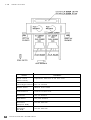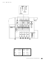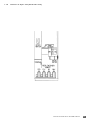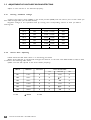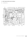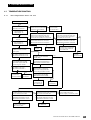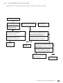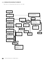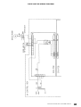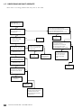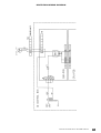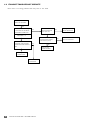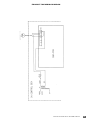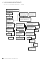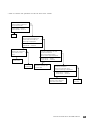
1
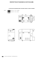
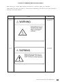
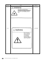
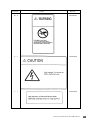
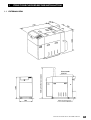
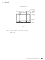
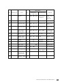
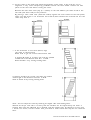
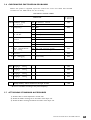
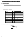
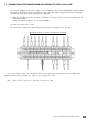
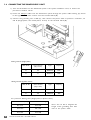
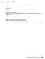
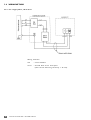
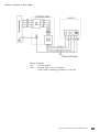
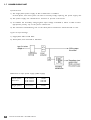
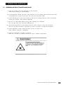
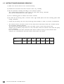
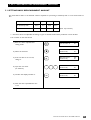
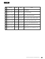
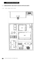
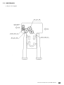
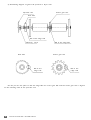
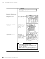
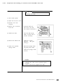
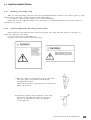
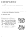
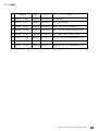
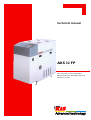
Technical manual
AKS 32 FP
Item code/code article: 170 000 049 A
Reference/référence: SAV MANU 018 ed 01
Date/date: 12.1998
Technical manual AKS 32 FP - SAV MANU 018 ed 01
1
SUMMARY GENERAL
2
INTRODUCTION
3
SAFETY PRECAUTIONS
5
SAFETY GUIDE (PRECAUTIONS ON USING THE SYSTEM)
6
DESCRIPTION OF SIGNAL WORDS
7
DESCRIPTION OF WARNING & CAUTION LABEL
8
LISTING OF WARNING AND CAUTION LABELS
9
INSTALLATION - PART A
13
MAINTENANCE - PART B
43
Technical manual AKS 32 FP - SAV MANU 018 ed 01
INTRODUCTION
Before using this system, be sure to read this instruction manual carefully.
Before using this system, read important warning carefully.
For the sake of safety, observe the precautions shown below in repair work.
1-
This system is used to process color negative roll film. Do not use it for other purposes.
2-
Operate your system properly according to this operation manual for safe and optimum performance.
3-
Always keep this operation manual near the system and observe all cautions and instructions as
required.
4-
Follow the instructions in this operation manual and observe all caution labels. For details, refer to the
"Description of Caution Labels".
5-
Install the system on a flat and stable surface, and do not expose the system to direct sunlight.
6-
The work environment conditions call for room temperature of 15°C - 30°C and relative humidity of 30% 80%. An optional cooling unit is required to maintain the processing performance of the negative
processor should room temperature exceed 30°C.
7-
The cabinet has ventilation holes to prevent a rise in temperature. Never block or cover the ventilation
holes with any objects.
8-
Never insert your hand or any object into the ventilation holes of the cabinet ; otherwise, you may suffer
eclectric shock.
9-
Except when indicaded in this operation manual and user maintenance manual, users are prohibited
from serving this system (by disassembling, remodeling, adjusting or using parts not specified). Should you
remove the cover not specified, you may be exposed to high voltage and the danger like electric
shock and burning yourself.
10 - Turn off the power source before initiating any maintenance indicated in this operation manual or the
user maintenance manual. Should the power not be switched off.
You may suffer electric shock.
11 - Never remove the attached caution labels.
12 - If this operation manual is missing, contact your dealer. Should caution labels peel off or become
stained or otherwise damaged, replace them with new ones.
13 - To purchase an additional operation manual or caution labels, contact your dealer or our sales division
as indicated on the back cover.
14 - When the waste solution is disposed of, contact an waste-article collector qualified by the national or
local government according to the law requiation.
15 - Machine noise informations for order 3.GSGV,18.01.1981 : the maximum sound pressure level is 70dB (A)
or less in accordance with ISO 7779.
Technical manual AKS 32 FP - SAV MANU 018 ed 01
3
INTRODUCTION
16 - Before starting any maintenance work described in this manual, be sure to turn off the power
completely. A failure to turn off the power may cause electric shocks, injury or damages to the film
processor.
17 - The film processor is grounded with the 3-wired power cable, etc...
Never disconnect the grounding wire to avoid electrocution.
18 - On completion of repair work, make certain that all removed screws, pads, etc..., are attached in the
proper positions.
19 - Do not use any substandard or nonstandard repair parts.
20 - Do not attempt to carry out any repair works not described in this manual.
21 - Never pull the cable to unplug the connector.
22 - After replacing or repair work, connect wire and cables carefully not to bring them into contact with
burrs or sharp edges. In particular, do not bring wires and cables into contact with movable parts or
driving parts.
4
Technical manual AKS 32 FP - SAV MANU 018 ed 01
SAFETY PRECAUTIONS
This machine has been checked in accordance with the laws pertaining to the various product safety
regulations before leaving the factory.
When serving it, be sure to observe the following precautions.
1-
Do not use fuses other than those of the specified ratings.
2-
Never modify electrical circuit.
3-
Do not use unspecified replacement parts.
4-
Confirm that all screws, pads and wiring which were removed for serving have been re-installed in their
original position.
5-
When disconnecting connectors, do not pull the wiring (particularly AC line wiring and high voltage
parts).
6-
Do not perform any unspecified modifications.
7-
Do not run the power cord where it is likely to stepped on or crushed.
8-
Carefully clean off chemical solutions adhering to electrical units.
9-
After replacing or repair work, route wiring in such a way that it does not touch burrs or other sharp
edges.
10 - Machine noise informations for order 3.GSGV,18.01.1981 : the maximum sound pressure level is 70dB (A)
or less in accordance with ISO 7779.
IMPORTANT NOTICE
Because inexperienced person servicing may causes hazards to people and to the
equipment, we,
KIS strongly recommends that all servicing is performed
only by our trained service engineer.
This machine must be disposed of as industrial waste.
Be sure the contact any qualified waste-article collector.
Technical manual AKS 32 FP - SAV MANU 018 ed 01
5
SAFETY GUIDE (Precautions on using the system)
Operation
Precaution
Label
position
Remark
1. Handling
chemicals
Wear safety gloves, protective glasses and
masks when handling solutions.
If solutions contact your eyes or skin, wash off
them with water for more than 15 minutes
and get medical treatment.
Chemicals may cause skin irritation.
W-3
Instruction
Section 7
Installation
Section 4
2 . Handling the
sprocket for
switching the
power
frequency
Fingers may be clipped!
The power breaker must be switched off
before handling the sprocket for swicthing
the power frequency.
W-4
3 . Handling the
chain and
sprocket
Fingers or hair may be clipped!
The power breaker must be switched off
before handling the chain for the sprocket.
W-2
4 . Handling the
drying heater
Your fingers may be burnt!
When handling the dryer heater, be sure to
turn off the power breaker and wait more
than 15 minutes before initiating operation.
5 . Replacing the
cutter blade
Your fingers may be cut!
The power breaker must be switched off
when changing the cutter blade.
6 . Replacing
fuse
You may suffer electric shock!
The power breaker must be switched off
before changing a blown fuse.
a
Service
Section 6
Service
Section 6
W-1
W-5
Maintenance
Section 2
Instruction
Section 18
C - 1
Installation
Section 3
L-1
Installation
Section 3
7 . Connecting the
input power
supply cord
See installation instructions before
connecting to the supply.
8 . Handling the
sprocket for
switching the
power frequency
(installation &
maintenance)
Fingers may be clipped!
The power breaker must be switched off
before handling the sprocket for switching
the power frequency
W-4
Section 6
9 . Handling the
chain and
sprocket
(installation &
maintenance)
Fingers or hair may be clipped!
The power breaker must be switched off
before handling chain for the sprocket.
W-2
Section 6
6
Technical manual AKS 32 FP - SAV MANU 018 ed 01
DESCRIPTION OF SIGNAL WORDS
- Signal words indicate the levels of potential danger.
- Signal words are categorized into three levels according to the possibility and seriouness of danger.
D a n g e r : indicates a situation of immediate danger which may result in serious injury or
death, if not avoided.
Warning : indicates a situation of potential danger which may result in serious injury or
death, if not avoided.
C a u t i o n : indicates a situation of potential danger which may result in slight or minor injury.
This term is also used for physical damage aside from personal risk and injury.
Probability of damage
Damage
Injury (and
physical
damage)
(High probality)
Damage may be
caused
(Low probality)
Death or serious injury
(Damage is serious)
Danger
Warning
Medium or slight injury
(Damage is slight)
Warning or Caution
Caution
Physical damage only
is
caused
Caution
- Example of the signal word.
Technical manual AKS 32 FP - SAV MANU 018 ed 01
7
DESCRIPTION OF WARNING & CAUTION LABEL
POSITION OF WARNING AND CAUTION LABELS TO BE ATTACHED
Note :
Attached on the outside
Attached on the inside
8
Technical manual AKS 32 FP - SAV MANU 018 ed 01
LISTING OF WARNING AND CAUTION LABELS
- Each warning or caution label should correspond to a position where it is attached.
- Order labels from the local office or sales division indicated on the back cover of this manual by
referring to the part numbers.
Position
Label
Part N°
W-1
L43-A6324
W-2
L43-A6327
Technical manual AKS 32 FP - SAV MANU 018 ed 01
9
Position
10
Label
Part N°
W-3
L43-A7581
W-4
L43-A6326
Technical manual AKS 32 FP - SAV MANU 018 ed 01
Position
Label
Part N°
W-5
L43-A6325
C - 1
L43-A6329
L-1
L43-A6320
Technical manual AKS 32 FP - SAV MANU 018 ed 01
11
12
Technical manual AKS 32 FP - SAV MANU 018 ed 01
PARTA
INSTALLATION
Technical manual AKS 32 FP - SAV MANU 018 ed 01
13
SUMMARY - PART A
1. ITEMS TO BE CHECHED BEFORE INSTALLATION
1.1. EXTERNAL VIEW
3
15
1.2. SPACE REQUIPMENTS
16
1.3. VENTILATION AND AIR-CONDITIONNING
16
1.4. TRANSPORTING MACHINE INSIDE INSTALLATION BUILDING
17
1.5. INSTALLING ON A SECOND STORY (LEASING A CRANE)
17
1.6. TRANSPORTING MACHINE TO INSTALLATION AREA
17
1.7. DISPODAL OF WASTE SOLUTION
17
2. INSTALLATION
2.1. UNPACKING PRECAUTIONS
18
2.2. UNPACKING PROCEDURE
18
2.3. PACKAGE
19
2.4. INSTALLATION OF PROCESSOR
22
2.5. LEVELING MACHINE
22
2.6. CHEKING DIP SWITCHES ON CPU BOARD
25
2.7. ATTACHING STANDARD ACCESSORIES
25
3. ELECTRICAL REQUIREMENTS AND CONNECTIONS
3.1. POWER CONSUMPTION
26
3.2. CONNETIONS AND RATED CAPACITIES
26
3.3. CONNECTING THE TRANSFORMER ACCORDING TO SUPPLY VOLTAGE
27
3.4. CONNECTING THE POWER SUPPLY UNIT
28
3.5. WIRING PRECAUTIONS
29
3.6. WIRING METHOD
3.6.1. For single-phase, three-wire
3.6.2. For 3-phase, 4-wire Power
30
30
31
3.7. POWER SUPPLY UNIT
32
4. MIXING THE CHEMICALS
4.1. GENERAL INSTRUCTIONS FOR SAFE USE
35
4.2. INSTRUCTIONS FOR MIXING CHEMICALS
36
5. SETTING BASIC REPLENISHMENT AMOUNT
5.1. SETTING BASIC REPLENISHMENT AMOUNT
37
5.2. SETTING PUMP (BELLOWS PUMP) REPLENISHMENT RATE
38
6. FUSES
7. STANDARD ACCESSORIES ACCOMPANYING DOCUMENTS
AND OPTIONS
14
7.1. STANDARD ACCESSORIES
40
7.2. ACCOMPANYING DOCUMENTS
42
7.3. OPTIONS
42
Technical manual AKS 32 FP - SAV MANU 018 ed 01
1
ITEMS TO BE CHECKED BEFORE INSTALLATION
1.1 EXTERNAL VIEW
Technical manual AKS 32 FP - SAV MANU 018 ed 01
15
2) Installation space (the minimum distance to the wall - unit : mm)
NOTE: the space for other equipments (paper processor, etc ...) should be also considered.
1.2 SPACE REQUIPMENTS
1) The machine weight is as follows.
Make sure that the floor is solid enough to support the weight.
Machine
weight Machine weight with solutions
170 kg
250 kg
2) A ceiling is required to be at least 1,7 m high to pull the racks out of the machine.
3) Do not install the machine in direct sunshine.
(Make use of blinds or curtains if they are necessary).
4) It is recommended to cover the floor with waterproof material because processing solutions may
be spilled on it.
5) Check for any inclination or unevenness of the floor.
1.3 VENTILATION AND AIR-CONDITIONNING
1) Since the film processors discharge hot air for drying, make sure the room is well-ventilated and
an air-conditioner is used in summer.
2) A heating system is recommended in winter to warm up the processing solution quickly and
provide operators a pleasant environment.
3) The working environment conditions call for room temperature of 18 - 28°C and relative humidity
of 30 - 80%. An optional cooling unit is required when the system is continuouly operated for 8
hours or more at the room temperature of 28°C or more.
16
Technical manual AKS 32 FP - SAV MANU 018 ed 01
1.4 TRANSPORTING MACHINE INSIDE INSTALLATION BUILDING
When transporting the machine trough the building doors, be sure to measure the actual door
dimensions.
The corrugated carton case measures 680 mm (W) x 1240 mm (L) x 1490mm (H).
If the package proves too large for ordinary doors, unpack the processor before bringing it into the
room.
1.5 INSTALLING ON A SECOND STORY (LEASING A CRANE)
- Make all the arrangements (crane arriving time & place, payment and who is
each work) carefully.
- Procure sufficient manpower. Be sure to take the safety measures.
- Check the transporting route and prepare the required tools.
responsible for
1.6 TRANSPORTING MACHINE TO INSTALLATION AREA
Choose the most convenient route to the installation area after thorough investigation of local
traffic conditions and the neighborhood.
1.7 DISPOSAL OF WASTE SOLUTION
Secure a place to store waste solution for later disposal by authorized agent.
Technical manual AKS 32 FP - SAV MANU 018 ed 01
17
2. INSTALLATION
2.1
UNPACKING PRECAUTIONS
1) Although the AKS 32 FP is both shipped in single packages, the packing method differs between products for
domestic and overseas markets (see fig. 2-1).
2) Before unpacking, make an investigation thoroughly about the installation place, transporting conditions and
unloading place from the pallet.
3) Unpack in a large area other than the installation room.
2.2
UNPACKING PROCEDURE
Overseas model
1) Cut the 2 packing bands with knife.
(since the bands may bound, care must be taken).
2) Remove the cap (top box).
3) Remove the accessory case and cushioning materials.
4) Pull out the 6 nails holding the case to the pallet.
5) Slip the case up and off.
6) Unload the equipement from the pallet.
7) Check the list of standard accessories & spare parts and attached documents for any missing items.
18
Technical manual AKS 32 FP - SAV MANU 018 ed 01
2.3
PACKAGE
Package of AKS 32 FP
Fig. 2-1
Package
Dimensions : 1240 mm (L) x 680 mm (W) x 1490 mm (H)
Weight : 230 kg
Technical manual AKS 32 FP - SAV MANU 018 ed 01
19
General Drawings (for overseas model)
P a c k a g e Dimensions : 1240 mm (L) x 680 mm (W) x 1490 mm (H)
Weight : 230kg
NOTE :
1) The code number, machine number, machine type, size and weight should be printed on the
particular area of shipping case.
2) The shipping case should be sealed with the black cloth tape, and tightened with polyester
bands en 2 places.
3) The package should withstand piling en 3 layers.
20
Technical manual AKS 32 FP - SAV MANU 018 ed 01
Description
N°
Drawing N°
Item
1
Pallet
2
Body
3
Q'ty
Dimension
L
W
H
Specification
1
1240
680 220
1
1220
660 1340 A A F
Corner post 1
3
1200
100 15
Honeycomb
Bent in the
center
4
Corner post 2
1
1200
100 15
Honeycomb
Bent in the
center
5
Top cover
hold plate
1
1180
810 23
AAF + AAF
Protecting
top cover
6
Air cap
1
910
650
Air cap
For tray
7
Body cover
(overseas)
1
1200
630 1300 Vinyl
Against dust
8
Band
2
19
Polyester
Trade item
9
Fastener
2
19
Polyester
Trade item
10
Cap nail
6
11
Polyester bag
1
12
Packing list
1
14
One set of
accessories
(1)
15
Packing
(1)
case
label
Wood & pol
yethylene
Remark
50L
400
Made by
pack
Mizutani
Trade item
280
For manuals
A4-size
copy paper
Technical manual AKS 32 FP - SAV MANU 018 ed 01
21
2.4
INSTALLATION OF PROCESSOR
To install CFP-232T/252TII, a 19mm wrench is
required to fix the 4 adjusting bolts and nuts
(see fig. 2-2) an addition to standard tools.
After preparation of the electrical system
(see the chapter "3. Electrical requirements and connections"
and the installation guide),
bring the machine into the room and install it
according to the following steps.
1) Carry the processor to the installation place. Install it at least 30cm aprt from the wall.
gsfdg
2) Lift the front (replenisher tank side) of the processor and put the tray under the processor.
2.5
LEVELING MACHINE
Rack leveling is required because the processor has a flexible structure (comb frames and panels are separate parts
and they are just bolted together).
First, check that the machine is level at the upper frames where the rack holders are attached and then reconfirm at
the racks.
The alignment of racks are very important for smooth film transport.
1) Carry the machine (equiped with caster) to the installation position and turn the leveling bolts until the casters
are lifted.
2) Leveling the machine.
a - Take off the top cover, and check the alignment of the racks on the upper right frame and upper left frame
respectively, and then cheek the level between right and left upper frames.
Do not check at the rack holders because they are not aligned (the diameters are differs). A spirit level longer
than 300mm is recommended.
After pouring solution into the tank, cheek the level by the spirit level again.
Note : after the above cheeking, make sure that the cop cover can be opened and
closed properly, and the crossover racks and the rack units can be easily
removed and set.
22
Technical manual AKS 32 FP - SAV MANU 018 ed 01
b - Set the racks in the tanks, and cheek the alignment of the racks, if the racks are not in
alignment, it may cause transporting problems because the short leader touches the side
plates of the next rack when crossing the racks.
Because the racks have some play (0 ~ 0,2mm) on the rack holders, put them all off to the
left side (rack drive side) of the processor.
By placing a 15cm metal ruler (with flat surface) against the outer surface of the rack plates,
make sure that there is not uneveness more than 0,5mm between the rack and the one two
racks away from it.
c - If the uneveness is more than 0,5mm, align
the racks as shown below.
Racks tend to get out of line toward lower side.
If position B and/or C is lower, the racks are pushed
toward left in the direction from N° 1 to N°8.
Raise B and/or C by turning leveling bolts.
If position A and/or D is lower, the racks are pushed
toward right in the direction from N°1 to N°8.
Raise A and/or D by turning leveling bolts.
Note : dot not adjust the level by lowering the higher side with leveling bolts.
Because the dryer rack side is so heavy that the machine can be supported by the other 3
leveling bolts with the adjusted one is floated, and the machine may be slanted in a long time.
I there is no choice, turn the casters with your hand to make certain that they do not touch the
floor.
Technical manual AKS 32 FP - SAV MANU 018 ed 01
23
d - Check that the racks are easily removed and
set. Remove the rack holders and lift the
rack 5-10mm up and release it to check that
it falls into the racks receiver smoothly.
Check each rack from N°1 to N°8.
(Be careful to avoid contamination because this is
done after the solution is poured into the tank).
e - Tighten the double nuts against the welded nuts
to lock the leveling bolts.
If the double nuts are not tightened enough,
the bolts become loose by vibration.
f - Request :
The machine may slant after installation.
Check that the machine is level a few weeks afterward.
Ask the customer to contact the service staff when the machine has to be reinstalled in
other place.
24
Technical manual AKS 32 FP - SAV MANU 018 ed 01
2.6 CHECKING DIP SWITCHES ON CPU BOARD
Before the power is supplied, open the control box cover and check that the DIP
switches on the CPU board are set correctly.
DIP SWITCH ON/OFF TABLE
FUNCTION
DS2-1Circulation pump
on-demand
Set position
on delivery
ON On-demand control
OFF When not used
ON
2 Frequency
ON 60Hz
OFF 50Hz
OFF
3 DRY temperature
for 120 film
ON Set temp. +20°C control
OFF Set temp. +10°C control
OFF
4 DRY temperature
control
ON 40°C control
OFF When not used
OFF
5 Low guard
ON 20°C control in cold-district
OFF When not used
OFF
6 Basic replenishment
rate setting
ON Basic repl. amount setting
OFF Repl. rate in % setting
OFF
7 Unused
8 For
OFF
debugging
(set to OFF)
OFF
DS3-1 Language
setting
ON
2 Language
setting
OFF
3 Language
setting
OFF
4 Language
setting
OFF
Backup battery switch located on the right of DS3
ON
* Be sure to set DS2-2 according to the power frequency.
2.7
ATTACHING STANDARD ACCESSORIES
1) Attach a filter to each temperature control tank.
2) Attach the leader receiving set to the outlet of the dryer unit.
3) Attach the films receiving box below the outlet of the dryer unit.
Technical manual AKS 32 FP - SAV MANU 018 ed 01
25
3. ELECTRICAL REQUIREMENTS AND CONNECTIONS
3.1 POWER CONSUMPTION
1) Power consumption per input voltage
Supply
voltage
Power consumption
220V
230V
240V
3.13kW
3.40kW
3.70kW
2) Electrical capacities of xarious units
Input
Description
Power consumption (50Hz)
Voltage
Q'ty
Heater
H1
240V
350W
1
Heater
H2
240V
350W
1
Heater
H3
240V
240W
1
H4, H5
240V
1250W
2
Circulation pump
PU2
100V
26W
1
Circulation pump
PU1.3-8
100V
15W
7
Replenishing
RPU1-4
100V
4.5W
4
M
100V
10W
1
Dryer fan
FAN2
100V
27W
1
Exhaust fan
FAN1
100V
17W
1
Cut solenoid
CUTSO
100V
24W
2
Push solenoid
PUSHSO
DC24V
12.7W
2
Lock solenoid
LOCKSO
DC24V
8W
Drying heater
pump
Drive motor
Cooling fan
FAN3
100V
8.5W
3.2 CONNECTIONS AND RATED CAPACITIES
L1
AKS 32 FP
N
26
Technical manual AKS 32 FP - SAV MANU 018 ed 01
220-240V
20A
1
1
3.3 CONNECTING THE TRANSFORMER ACCORDING TO SUPPLY VOLTAGE
The primary voltage of the power supply is set to 230ACV when the CL-KP32TQA2 is delivered from
the factory. Should the service voltage be other than AC 230V, change the setting accordingly.
Available primary taps include 220, 230 and 240 ACV.
1) Read the voltage across the terminals immediatly to the line side of the circuit breaker on the
distribution panel.
Check the power frequency on the left (50/60Hz).
2) Open the control box cover.
3) Remove the control box cover and locate the power transformer on the left.
Detailed drawing of power transformer terminals
For a line viltage other than AC 230V, remove the connected cable attached to the 230V taps
(hatched cord), then attached this cable to the appropriate taps.
Note : Make sure that the circuit is dead when connecting the cable.
Technical manual AKS 32 FP - SAV MANU 018 ed 01
27
3.4 CONNECTING THE POWER SUPPLY UNIT
1) Turn off the breaker on the distribution panel is the system installation room, as well as the
processor's breaker switch.
2) Insent the Cabtyre cable from the distribution panel through the power cable bushing (A) shown
in the figure below, then connect into the terminal block (B).
3) Connect the grounding wire to PE (C), then connect the power cable to position L and N/L1, L3
and N (Single-phase, two-wire/3-phase, 4-wire) on the terminal block (B).
Wiring material (Single-phase)
AKS 32 FP
Cross-section
(SQ = mm²)
Type
Capacity
O
2.5
H05VV-F
25A
O
4
H05VV-F
32A
AKS 32 FP
Cross-section
(SQ = mm²)
Type
Capacity
O
1.5
H05VV-F
16A
O
2.5
H05VV-F
25A
Wiring material (3-phase 4-wire)
For processor Wiring sizes (Single-phase, 3-phase 4-wire)
28
Outer diameter (mm)
Power cable Bushing
8.5-10.5
SCL-10B
10.5-12.5
SCL-14A
12.5-14.5
SCL-14B
Technical manual AKS 32 FP - SAV MANU 018 ed 01
Note : do not fail to lengthen the
length of the grounding wire than
that of the power cable.
3.5
WIRING PRECAUTIONS
1) Grounding Fault Circuit Interrupter (GFCI)
For safety's sake attach a circuit breaker (GFCI) to each feeder line to the distribution panels.
2) Grounding Line
Be sure to use an isolated PE wire instead of a neutral PE conductor for grounding.
If such a PE wire is not available, use an additional wire.
3) Connection of other equipment
When equipment other than the AKS 32 FP are connected to the same distribution panel, be sure to note the
following points.
- The unbalance factor (load balancing of L1 and L2).
- The capacity of yhe main-line breaker.
- The need for an earth leakage breaker to protect additional equipment.
4) Leakage current detection sensitivity of each leakage breaker
Basically, the 30mA-type earth leakage breaker should be used.
Should a highly sensitive breaker be used in the branch circuit, however, use an eath leakage breaker with higher
sensitivity.
Technical manual AKS 32 FP - SAV MANU 018 ed 01
29
3.6 WIRING METHOD
3.6.1 For single-phase, three-wire
Wiring materials
30
CB
: Circuit Breaker
CFCI
: Ground fault circuit interrupter
(fault current detecting sensitivity = 30 mA).
Technical manual AKS 32 FP - SAV MANU 018 ed 01
3.6.2 For 3-phase, 4-wire Power
Wiring materials
CB
: Circuit breaker
CFCI : Ground fault circuit interrupter
(fault current detecting sensitivity = 30 mA).
Technical manual AKS 32 FP - SAV MANU 018 ed 01
31
3.7 POWER SUPPLY UNIT
Specifications
1) The single-phase power supply of 220 to 240 ACV is standard.
A three-phase, four-wire system can also be used by simply replacing the power supply unit.
2) The power supply unit should have a function to prevent overcurrent.
3) To stabilize the secondary voltage against input voltage of AC220 V, 230 V or 240 V select
appropriate primary tap of the power transformer.
4) The maximum load balancing rate of the three-phase transformer should be 30% or less.
Types of Input Voltage
1) Single-phase 220 to 240 ACV.
2) Three-phase, four-wire 220 to 240 ACV
Difference in input power supply (240V supply)
32
Three-phase
Four-wire
L1-N section
L2-N section
L3-N section
1.2 kW
1.25 kW
1.25 kW
Single-phase
L-N section
3.7 kW
Technical manual AKS 32 FP - SAV MANU 018 ed 01
Load sharing
1) Single-phase
system
2) Three-phase, four-wire system
Technical manual AKS 32 FP - SAV MANU 018 ed 01
33
Wiring of Power Supply Unit
Single-phase, two-wire power supply unit
Three-phase, four-wire power supply unit
How to replace an optional power supply unit
1) Take off the control box cover.
2) Pull out connector CN1 out.
3) Remove the two screws that secure TB1 in place.
4) Remove the grounding wire from PE.
5) Remove the two screws that secure the breaker unit in place.
6) Follow the above procedures in reverse (i.e, steps 5 to 1) to attach an optional power supply
unit.
34
Technical manual AKS 32 FP - SAV MANU 018 ed 01
4. MIXING THE CHEMICALS
4.1 GENERAL INSTRUCTIONS FOR SAFE USE
1) Keep the contact with the chemicals to the minimum.
Treat them carefully to avoid spillage.
2) If the chemicals contact your skin, wash off with a lot of running water and then with soap.
If the developer is spilt on your skin, the same step should be made.
3) If the chemicals get in your eyes, wash out with lots of running water for about 15 minutes.
If the pain remains, seek medical treatment.
4) Be sure to wash hands before eating, after handling the chemicals.
Do not take food into chemical handling area.
5) The processing tanks for the machine must be used to keep or carry the chemicals.
Do not use other containers, especially for food, to measure or keep the chemicals.
6) If the chemicals is drunk, drink salt water at once to spew it up.
Seek medical treatment immediatly.
7) Keep the chemicals in a dark, cool place.
Keep out of reach of children because of acid or alkaline components.
Technical manual AKS 32 FP - SAV MANU 018 ed 01
35
4.2 INSTRUCTIONS FOR MIXING CHEMICALS
1) Make sure that the drain cock is turned off firmly.
2) Handle the removed racks and crossover racks very carefully.
3) Mix all chemicals carefully according to the solution manual.
The contamination-preventive cover must be used when mixing chemicals.
(see the list shown below for tank capacity).
4) Use a measuring glass to measure the starter solution.
5) Put back the processing racks, crossover racks, light shield plates and rack retaining plates after
mixing chemicals.
36
*
Install the processing rack into the processing tank carefully in order to prevent contamination.
*
The solution level in the filter section of the temp.control tank drops while the circulation pump
for processing solution operates.
The solution level should reach the line in the filter section of the temp.control tank.
Operate the circulation pump and turn it off, and them check the solution level while the pump
is not operating.
Pour the chemicals into N3-2 and N4-3 tanks whose solution levels go down because their
solutions are circulated into the hoses which control their next tanks.
TANK
DEV
BL
FIX-1
FIX-2
STB-1
STB-2
STB-3
CAPACITY (L)
16.7
4.4
4.2
4.6
3.2
3.4
3.8
Technical manual AKS 32 FP - SAV MANU 018 ed 01
5. SETTING BASIC REPLENISHMENT AMOUNT
5.1 SETTING BASIC REPLENISHMENT AMOUNT
The values below refers to the chemical volumes required* for processing a 135-24 exp. film or a one meter linear of
film.
135 film format
DEV
BL
FIX
STB
mL or 24 exp. film
23.0
5.0
33.0
40.0
mL or m.film
20.9
4.5
30.0
36.4
(basic repl. amount)
* : this basics values are adjustable according to type of chemical used and the production of the machine.
Turn on DS-6 on the CPU board
1) Enter the basic replenishment
setting mode.
2
REPL
PRM
2) Select the chemical.
3) If the set value is not correct,
change it.
4) Input the new value.
(ex. 20.9 mL)
5) Confirm the display and lock it.
SET
Set basic
reple. amount in %
50
DEV basic amount
(35.5ml 21.75)
xx
50
DEV basic amount
(35.5ml 21.75)
15%
50
The cursor appears
2
YES
0
9
DEV basic amount
(20.9ml 21.75)
15%
50
DEV basic amount
(20.9ml 21.75)
15%
50
6) Now the basic replenishment rate
is set.
Technical manual AKS 32 FP - SAV MANU 018 ed 01
37
5.2
SETTING PUMP (BELLOWS PUMP) REPLENISHING RATE
Measure each chemical (DEV, BL, FIX, STB) tank's bellows pump replenishing rate with the measuring glass. Input the
measured rate to fix the bellows pump replenishing rate for processing 1-meter-long film.
* Turn off DS2-6 on the CPU board
1) Enter the pump replenishing rate
setting mode.
2
REPL
PRM
x5
2) Select the pump.
Set pump
replenishing rate
DEV pumping rate
90 mL/min 50
3) Operate the selected pump for
60 seconds (The buzzer sounds
when the operation is finished).
* Measure the bellows pump
replenishing amount with the measuring
glass.
Do not take the first replenishing rate
into account because the pump
contains air.
Measure 3 times and calculate the
average (98 mL).
4) Press SET key to display the
cursor.
5) Input the average value (98mL)
6) Confirm the display and lock it.
DEV replenishing
60.0 sec
YES
50
The time is counted down on the
display
DEV pumping rate
_90 mL/min
SET
0
YES
9
8
DEV Pumping rate
98 mL/min
50
50
DEV Pumping rate
98 mL/min 50
When the setting is finished,
the cursor disappears
7) Now the pump replenishing rate is
set.
Pour the measured solution back into the tank
38
Technical manual AKS 32 FP - SAV MANU 018 ed 01
6. FUSES
N°
RATING
TYPE
SIZE
LOAD
F1
AC250V
3.15A
NORMAL Ø5.2x20mm
DEV HEATER
F2
AC250V
3.15A
NORMAL Ø5.2x20mm
FIX-2, STB-3 HEATER
F3
AC250V T3.15A
TIMELAG Ø5.2x20mm
DEV-2 CIRCULATION PUMP
F4
AC250V T3.15A
TIMELAG Ø5.2x20mm
DEV-1, BL, FIX-1, FIX-2, CIRCUL. PUMP
F5
AC250V T3.15A
TIMELAG Ø5.2x20mm
STB-1, STB-2, STB-3 CIRCUL. PUMP
F6
AC250V T3.15A
TIMELAG Ø5.2x20mm
DEV, BL, FIX, STB REPLENISHING PUMP
F7
AC250V T2A
TIMELAG Ø5.2x20mm
DRYER FAN
F8
AC250V T3.15A
TIMELAG Ø5.2x20mm
DRIVE MOTOR, CUT SOLENOID (L), (R)
Technical manual AKS 32 FP - SAV MANU 018 ed 01
39
7. STANDARD ACCESSORIES ACCOMPANYING DOCUMENTS AND
OPTIONS
7.1 STANDARDS ACCESSORIES
Case N°
1
*
*
*
*
N°
1
2
3
4
5
6
7
8
9
10
11
12
13
14
15
16
17
18
19
20
21
22
23
Part Name
Q'ty
Film receiving box
Short leader receiving box
Chemical filter set
Crank handle
Tray for body
Film splicer
Short leader
Splicing tape
Control strip magazine (126)
Bat
Turnguide rack washing bat
Splash guard
Drain hose
Tape cutter tray
Wash bottle
Tool set (with tool bag)
Spare fuse set
(see the following list)
Spare parts
(see the following list)
120 film magazine
110 film attachment
126 film attachment
Ball
Cut
1 unit
1 set
7 sets
1 pc.
1 pc.
1 set
15 shts
1 pc.
1 pc.
1 pc.
1 pc.
1 pc.
1 pc.
1 set
1 pc.
1 set
1 set
1set
1 pc.
2 pcs.
2 pcs.
1set
1 pc.
Spare parts details
Ring Ø3 blue
Ring Ø4 yellow
Ring Ø5 gray
Ring Ø6 white
Drive pocket
Pin
43-A0483
43-25022-2
43-05838-2
43-85464-1
43-05076-1
Z72022006
3
3
10
3
2
2
pcs.
pcs.
pcs.
pcs.
pcs.
pcs.
Spare fuse set
ZLI314010
ZLI314003
ZLI313004
1 pc.
1 pc.
1 pc.
ZLI216315
ZLI218315
ZLI218002
1 pc.
1 pc.
1 pc.
Tool set
Tool gag
Phillips screw driver
Flat screw driver
Double-end sparner (13X10)
Double-end sparner (8X7)
Hexagon wrench 2.0
Hexagon wrench 3.0
Hexagon wrench driver 2.0
Tool (terminal) 210-120J
40
Technical manual AKS 32 FP - SAV MANU 018 ed 01
1
1
1
1
1
1
1
1
1
pc.
pc.
pc.
pc.
pc.
pc.
pc.
pc.
pc.
* Attached to the
machine body
Technical manual AKS 32 FP - SAV MANU 018 ed 01
41
7.2 ACCOMPANYING DOCUMENTS
N°
Name
Q'ty
1
Packing list
1 pc.
2
Manual
1 set
7.3 OPTIONS
N°
42
1
110 film magazine
2
120 film magazine
3
126 film magazine
4
Cleaning unit
5
Cooling fan unit
6
Emergency dark bag
7
3-phase, 4-wire power source unit
Technical manual AKS 32 FP - SAV MANU 018 ed 01
PARTB
MAINTENANCE
Technical manual AKS 32 FP - SAV MANU 018 ed 01
43
SUMMARY - PART B
1. DESCRIPTION OF PARTS
1.1. ARRANGEMENT AND FUNCTION OF ELECTRICAL PARTS
1.1.1. Power supply control section
1.1.2. Interior of set box
1.1.3. Right side view
1.1.4. Left side view
1.1.5. Interior of dryer unit (back side view)
3
46
46
48
49
50
51
2. DESCRIPTION OF PRINT BOARD AND CHECK
2.1. CPU PRINT BOARD
2.2.1. Test points (CPU print board)
2.1.2. LED
2.1.3. Volume
52
52
52
53
2.2. SSR PRINT BOARD
2.2.1. Table of each loard
54
54
3. ADJUSTMENT OF CPU PRINT BOARD
3.1. ADJUSTING THE CPU PRINT BOARD
55
3.2. ADJUSTING TEMPERATURE
3.2.1. Standard voltage
3.2.2. Sensor amplifier
55
55
55
3.3. ADJUSTMENT OF VOLTAGE FOR FILM DETECTING
3.3.1. Setting standard voltage
3.3.2. Check after adjusting
56
56
56
3.4. PRINT BOARD FIGURE & CIRCUIT DIAGRAM
3.4.1. CPU Print board
3.4.2. SSR Print board
57
57
59
4. TROUBLE SHOOTING
4.1. TEMPERATURE CONTROL
4.1.1. The temperature does not rise
4.1.2. The dryer temperature does not rise
4.1.3. The temperature does not go down
4.1.4. The dryer temperature does not rise
61
61
62
63
64
4.2. CIRCULATION PUMP DOES NOT OPERATE
66
4.3. REPLENISHER PUMP DOES NOT OPERATE
68
4.4. DRIVE MOTOR DOES NOT OPERATE
70
4.5. DRYER FAN DOES NOT OPERATE
72
4.6. EXHAUST FAN DOES NOT OPERATE
74
4.7. LOCK SOLENOID DOES NOT OPERATE
76
4.8. PUSH SOLENOID DOES NOT OPERATE
79
4.9. FILM CUT SOLENOID DOES NOT OPERATE
82
5. WHERE TO CHECK THE MECHANICALS
5.1. PROCESSING RACK
85
5.2. DRYER RACK
87
6. MAINTENANCE
44
6.1. DAILY INSPECTION
89
6.2. WEEKLY
6.2.1.
6.2.2.
6.2.3.
6.2.4.
6.2.5.
6.2.6.
6.2.7.
89
89
89
89
89
90
91
92
INSPECTION
Checking and cleaning of dryer air filter
Checking patrone holder
Checking rack unit functioning
Cleaning rack unit
Checking rack unit operation
Inspection and cleaning of crossover rack and STB-3 rack unit
Cleaning and changing chemical filter
6.3. MONTHLY INSPECTION A
6.3.1. Cleaning processing tank
6.3.2. Tension adjustment and oiling of drive chain
6.3.3. Checking replenishing pump and circulation pump
6.3.4. Checking and oiling of the movable parts (chain)
6.3.5. Changing chemical filter
6.3.6. Checking processing temperature
6.3.7. Cleaning the inside of the machine
93
93
93
94
94
94
94
94
6.4. MONTHLY INSPECTION B
6.4.1. Cleaning loading unit drive roller
94
94
6.5. SIX-MONTH INSPECTION
6.5.1. Checking the damage of rubber socket and elbow
6.5.2. Checking and cleaning of the electric components
95
95
95
Technical manual AKS 32 FP - SAV MANU 018 ed 01
6.5.3. Checking the wear of bearing
6.5.4. Checking and cleaning of processing tank
6.5.5. Checking the leakage of replenisher tanks and replenisher pumps
and their cleaning
6.5.6. Checking temperature control heater
6.5.7. Measuring the pump replenishing rate
95
95
95
95
95
6.6. YEARLY INSPECTION
6.6.1. Cleaning tank
6.6.2. Cleaning dryer rack
6.6.3. Changing dryer air filter
96
96
96
96
6.7. FUSES
97
Technical manual AKS 32 FP - SAV MANU 018 ed 01
45
1
DESCRIPTION OF PARTS
1.1 ARRANGEMENT AND FUNCTION OF ELECTRICAL PARTS
1.1.1
46
Power supply control section
Technical manual AKS 32 FP - SAV MANU 018 ed 01
NAME
CONTENTS
CONTROL PANEL
Keyboard PCB, switches, (Operation, Drive)
CPU PCB
CPU PCB
SSR PCB
Circulation pump, Replenisher pump cut solenoid
Drive motor, Drive PCB for dryer fan
RE
Power source for CPU PCB (+DC5V)
DS
Rectifier (DC+24V)
C1
Smoothing condenser (DC+24V)
NF
Noise filter (AC200V)
TB1
Connecting terminal (for input supply)
TB2
Connecting terminal (for chemical heater)
CN1
Connecting terminal (for input supply)
CTB
Repeating
TF
Transformer
SSR21, 22
SSR for dryer heater
CP-1
Circuit protect for dryer heater
CP-2
Circuit protect for dryer heater
CP-3
Circuit protect for 5V DC line and exhaut fan
CP-4
Circuit protect for 24V DC line
NBF
Main
terminal
breaker
Technical manual AKS 32 FP - SAV MANU 018 ed 01
47
1.1.2
Interior of set box
NAME
48
CONTENTS
Cover switch
(Micro switch)
Open/Close detection of set box cover
Left & Right solenoid
Film cut solenoid
Reader-Sensor
Detects short leader
Lock-Solenoid
Lock for set box cover
Cut-Sensor
For cut solenoid
Push-Sensor
For push solenoid
Film-Sensor
(Projector PCB)
For film detection
Film-Sensor
(PT PCB)
For film detection
Technical manual AKS 32 FP - SAV MANU 018 ed 01
1.1.3
Right side view
DEV
Heater
240V
350W
FIX2
Heater
240V
350W
STB3
Heater
240V
240W
DRYER
Heater
240V
1250Wx2
Technical manual AKS 32 FP - SAV MANU 018 ed 01
49
1.1.4
50
Left side view
Technical manual AKS 32 FP - SAV MANU 018 ed 01
1.1.5
Interior of dryer unit (back side view)
Technical manual AKS 32 FP - SAV MANU 018 ed 01
51
2. DESCRIPTION OF PRINT BOARD AND CHECK
2.1 CPU PRINT BOARD
The CPU print board contains micro computers and controls the machine.
The temperature is also controlled by the CPU board.
2.1.1
2.1.2
Test points (CPU print board)
CPU P. BOARD
CONTENTS
TP 5
+5V Supply Voltage
DC 5V +0,1
TP 4
5V GND
between TP5 and TP4
0
LED
LED N°
52
CHECK POINTS
CONTENTS
LED ON
LD 1
110 Film left side
When film is defected
LD 2
135 Film left side
When film is defected
LD 3
120 Film left side
When film is defected
LD 4
120 Film right side
When film is defected
LD 5
135 Film right side
When film is defected
LD 6
110 Film right side
When film is defected
LD 7
Unused
LD 8
CPU RUN
Technical manual AKS 32 FP - SAV MANU 018 ed 01
When CPU operates properly
2.1.3
Volume
VR
CONTENTS
ADJUSTMENT
1
LCD Brightness
The brightness of indicator
2
DEV Temp. control offset
3
FIX2 Temp. control offset
Make the display show accurate reading
4
STB3 Temp. control offset
of the actual temperature
5
DRY Temp. control offset
6
Unused
7
Temp control analog
standard
voltage
4.096V+0.001V between TP1-TP4
8
L/R 135 film detecting
comparator
standard
voltage
3.00V+0.05V between TP2-TP4
9
L/R 135 film detecting
comparator
standard
voltage
2.5V+0.05V between TP3-TP4
Technical manual AKS 32 FP - SAV MANU 018 ed 01
53
2.2 SSR PRINT BOARD
SSR print board controls signals sent from CPU at the adequate voltage to the load of each signal.
2.2.1
Table of each loard
LOAD
LED N°
SSR N°
FUSE N°
DEV HEATER
LD1
SSR1
FIX2 HEATER
LD2
SSR2
STB3 HEATER
LD3
SSR3
DEV CIRCULATION PUMP
LD4
SSR4
COOLING FAN (OPTION)
LD5
SSR5
DEV CIRCULATION PUMP
BL, FIX1, 2 CIRCULATION PUMP
LD6
SSR6
F4
STB1, 2, 3 CIRCULATION PUMP
LD7
SSR7
F5
DEV REPLENISHER PUMP
LD9
SSR9
BL REPLENISHER PUMP
LD10
SSR10
FIX REPLENISHER PUMP
LD11
SSR11
STB REPLENISHER PUMP
LD12
SSR12
DRY FAN
LD13
SSR13
DRIVE MOTOR
LD14
SSR14
CUT SOLENOID (LEFT)
LD15
SSR15
CUT SOLENOID (RIGHT)
LD16
SSR16
PUSH SOLENOID (LEFT)
(SET BOX)
LD17
TR1
PUSH SOLENOID (RIGHT)
(SET BOX)
LD18
TR2
PUSH SOLENOID (LEFT)
(SET BOX)
LD19
TR3
DRY HEATER
LD21
SSR21
SSR22
F1
F2
F3
F6
F7
F8
Technical manual AKS 32 FP - SAV MANU 018 ed 01
D2W 203LD
AC200V
D2W 203LD
AC100V
D2W 202LD
AC100V
D2W 203LD
AC100V
D2W 2032D
AC100V
D2W 203LD
AC100V
D2W 203LD
AC100V
D2W 202LD
AC100V
CP-4
(not included
in PCB)
CP-1
CP-2
(not included in PCB)
54
REMARK
2SD633
DC24V
S5C-215L
3. ADJUSTMENT OF CPU PRINT BOARD
3.1 ADJUSTING THE CPU PRINT BOARD
Apply voltage testor between check pin TP5-TP4 (GND) on the CPU print board and adjust the voltage 5V +0.1/-0 by turning the volume on 5V switching regulator.
3.2 ADJUSTING TEMPERATURE
There are two steps: adjustment of the standard voltage of A/D converter and bias adjustment of
sensor amplifier.
3.2.1
Standard
voltage
Adjust the voltage 4.096V +0.001V between TP1-TP4 check pin with VR7.
3.2.2
Sensor amplifier
Operate the machine and adjust the temperature by turning the following volume until the displayed
temperature is in accordance with the temperature measured in the tank.
(see figure of CPU print board)
DEV
VR2
FIX2
VR3
STB3
VR4
DRYER
VR5
Note : Actual temperature should be measured
near the thermistor to be measured.
Take the filter out of the tank when
temperature is actually measured.
Technical manual AKS 32 FP - SAV MANU 018 ed 01
55
3.3 ADJUSTMENT OF VOLTAGE FOR FILM DETECTING
Adjust in case the film is not detected properly.
3.3.1
Setting standard voltage
Connect the tester's minus (GND) to the check pin TP4 (GND) and the tester's plus to each check pin
from TP2 throught TP3 (see the table below).
Regulate voltage to the specified value by turning the corresponding volume of each pin before
inserting film.
3.3.2
CHECK PIN N°
SPECIFIED V
VR N°
110 L
TP3
2.55V + 0.05V
VR9
135 L
TP2
3.00V + 0.05V
VR8
120 L
TP3
2.55V + 0.05V
VR9
110 R
TP3
2.55V + 0.05V
VR9
135 R
TP2
3.00V + 0.05V
VR8
120 R
TP3
2.55V + 0.05V
VR9
Check after adjusting
LD4-9
When
or blink as
(Make
should be OFF when there is no film being processed.
each sized film is transported throught the detector at the inlet each LED should be ON or OFF
the following table shows.
sure that film spliced to the short leader properly).
LED N°
SENSOR
NO FILM
FILM IN PROCESS
110
135/126
120
LD1
110 L
X
O
O/O
O
LD2
135 L
X
X
/O
O
LD3
120 L
X
X
X/X
O
LD6
110 R
X
O
O/O
O
LD5
135 R
X
X
/O
O
LD4
120 R
X
X
X/X
O
: BLINK
X: OFF
O: ON
56
SENSOR
Technical manual AKS 32 FP - SAV MANU 018 ed 01
3.4 PRINT BOARD FIGURE & CIRCUIT DIAGRAM
3.4.1
CPU Print board
Technical manual AKS 32 FP - SAV MANU 018 ed 01
57
CPU BOARD CIRCUIT DIAGRAM
58
Technical manual AKS 32 FP - SAV MANU 018 ed 01
3.4.2
SSR Print board
Technical manual AKS 32 FP - SAV MANU 018 ed 01
59
SSR BOARD CIRCUIT DIAGRAM
60
Technical manual AKS 32 FP - SAV MANU 018 ed 01
4. TROUBLE SHOOTING
4.1 TEMPERATURE CONTROL
4.1.1
The temperature does not rise
The temp. does not rise
YES
NO
Check that the LED on
SSR-PCB is turned on.
DEV heater: F1
FIX2 heater: F2
STB3 heater: F3
YES
YES
Check the fuses
are OK
Check that the display NO Change the temp.
shows the accurate read
sensor confirm
ing of the actual temp.
the connection
NO
DEV heater: F1
FIX2 heater: F2
STB3 heater: F3
YES
Check that the voltage is
AC200V on the terminal
board (TB2)
DEV heater: between S1-T1
FIX2 heater: between S1-T2
STB3 heater: between S1-T3
YES
Check the resistance of
each heater after cutting
the power supply and disconnecting the heater.
DEV heater: 155~175 Ω
FIX2 heater: 155~175 Ω
STB3 heater: 225~250 Ω
YES
NO
Confirm the
Change
connection
of each heater. the heater
Check that the voltage is less
than DC0.7V between the connector (J6) on SSR-PCB and the
check pin TP4 (GND) on CPU-PCB.
NO
DEV heater: between J6-1A-TP4
FIX2 heater: between J6-1B-TP4
STB3 heater: between J6-2A-TP4
YES
Confirm the connection
of J6 on CPU-PCB and
J6 on SSR-PCB.
Change
the SSR-PCB
NO
Check that the voltage is
AC200V on the terminal
board (TB2)
NO
Change
the CPU-PCB
DEV heater: between R1-S1
FIX2 heater: between R2-S1
STB3 heater: between R3-S1
YES
Check the continuity of each
bimetal after cutting the
the power supply and disconnecting bimetal on TB2.
DEV: between R1-T1 (Bi1)
FIX2: between R2-T2 (Bi2)
STB3: between R3-T3 (Bi3)
YES
NO
Confirm the
connection of
each bimetal.
Change
the bimetal
Check that the voltage is
AC200V between the connector NO
(J4) on SSR-PCB and TB2.
Check that the voltage is
NO Confirm the connector
(J3) on SSR-PCB or the
AC200V between the connector
power supply connector (CN1).
(J3) on SSR-PCB and TB2.
DEV heater: between J4-1-S1
FIX2 heater: between J4-2-S1
STB3 heater: between J4-3-S1
DEV heater: between J3-1-S1
FIX2 heater: between J3-2-S1
STB3 heater: between J3-3-S1
YES
Confirm the connection
between the (J4) on
SSR-PCB and TB2.
NO
DEV heater: between J6-1A-TP4
FIX2 heater: between J6-1B-TP4
STB3 heater: between J6-2A-TP4
YES
Change
the fuse.
Check that the voltage is less
than DC0.7V between the connector (J6) and the check pin
TP4 (GND) on CPU-PCB.
YES
Change
the SSR-PCB.
Technical manual AKS 32 FP - SAV MANU 018 ed 01
61
4.1.2
The dryer temperature does not rise
The temp. does not rise
YES
NO
Check that the LED on
SSR-PCB is turned on.
DRY heater: LD21
Check that the display
shows the accurate reading of the actual temp.
NO Change the temp.
sensor confirm
the connection
YES
YES
Check the circuit
protector are OK
NO
Check that the voltage is less
than DC0.7V between the connector (J6) on SSR-PCB and the
check pin TP4 (GND) on CPU-PCB.
NO
DRY1 heater: between J6-11A-TP4
DRY2 heater: between J6-11B-TP4
DRY1 heater: CP-1
DRY2 heater: CP-2
Check that the voltage is less
than DC0.7V between the connector (J6) and the check pin
TP4 (GND) on CPU-PCB.
DRY1 heater: between J6-11A-TP4
DRY2 heater: between J6-11B-TP4
YES
YES
YES
Check that the voltage is
AC200V on the dryer
terminal board (TB3)
DRY1 heater: between R4-S2
DRY2 heater: between R5-S3
YES
Check the resistance of
each heater after cutting
the power supply and disconnecting the heater.
Change the circuit protector.
Confirm the
connection
of each heater.
Change
the SSR-PCB
Check that the voltage is
AC200V on the terminal
board (TB2)
NO
Check that the voltage is
AC200V between TB2 and the
SSR (the output side).
YES
YES
Confirm the connection
between them.
NO
NO
Check the continuity of each
bimetal after cutting the
the power supply and disconnecting bimetal on TB2.
Check that the voltage is
AC200V between TB2 and the
SSR (the input side).
DRY1 heater: between S2-SSR21
DRY2 heater: between S3-SSR22
YES
NO
Change
the bimetal
NO
YES
Check that the SSR input
voltage is DC5V.
Confirm the connector
of the power supply
connector (CN1).
SSR21: between + SSR22: between + YES
Change
the SSR.
62
Change
the CPU-PCB
DRY1 heater: between S2-SSR21
DRY2 heater: between S3-SSR22
DRY1 heater: between R4-S2
DRY2 heater: between R5-S2
Confirm the connection
between TB2 and TB3.
Change
the heater
Confirm the connection
of (J6) on CPU-PCB and
(J6) on SSR-PCB.
NO
DRY1 heater: 40~50 Ω
DRY2 heater: 40~50 Ω
YES
NO
Technical manual AKS 32 FP - SAV MANU 018 ed 01
NO
Confirm the connection
between the connector
(J9) on SSR-PCB and
the SSR.
4.1.3
The temperature does not go down
(When there is nothing wrong with the liquid surface and circulation pumps).
The temp. does not rise
YES
Check that the LED on
SSR-PCB is turned off.
NO
DEV heater: LED1
FIX2 heater: LED2
STB3 heater: LED3
Check that the display
shows the accurate reading of the actual temp.
Check that the voltage (DC4~5V)
NO
is measured between the connector
(J6) on SSR-PCB and the check
pin TP4(GND) on CPU-PCB.
NO
DEV heater: between J6-1A-TP4
FIX2 heater: between J6-1B-TP4
STB3 heater: between J6-2A-TP4
DEV heater: between S1-T1
FIX2 heater: between S1-T2
STB3 heater: between S1-T3
YES
Cooling unit
(option) is
required.
Change the temp.
sensor confirm
the connection
YES
YES
Check that the power is shut
off between the following
terminals on the TB2
NO
YES
Change
the SSR-PCB
Check that the voltage (DC4~5V)
NO
is measured between the connector
(J6) and the check pin TP4 (GND)
on CPU-PCB.
DEV heater: between J6-1A-TP4
FIX2 heater: between J6-1B-TP4
STB3 heater: between J6-2A-TP4
YES
Confirm the connection
of (J6) on CPU-PCB and
(J6) on SSR-PCB.
Change
the CPU-PCB
Technical manual AKS 32 FP - SAV MANU 018 ed 01
63
4.1.4
The dryer temperature does not rise
(When there is nothing wrong with the liquid surface and circulation pumps).
The temp. does not rise
YES
Check that the LED on
SSR-PCB is turned off.
NO
Check that the display
shows the accurate reading of the actual temp.
NO
Change the temp.
sensor confirm
the connection
DRY heater: LED21
YES
YES
Check that the power is shut
off between the following
terminals on the TB2
NO
DRY1 heater: between R4-S2
DRY2 heater: between R5-S3
Check that the voltage (DC4~5V)
NO
is measured between the connector
(J6) on SSR-PCB and the check
pin TP4(GND) on CPU-PCB.
DRY1 heater: between J6-11A-TP4
DRY2 heater: between J6-11B-TP4
YES
YES
Confirm the connection
between the (J4) on
SSR and TB2.
Change
the SSR
Change
the SSR-PCB
Check that the voltage (DC4~5V)
NO
is measured between the connector
(J6) and the check pin TP4 (GND)
on CPU-PCB.
DRY1 heater: between J6-11A-TP4
DRY2 heater: between J6-11B-TP4
YES
Confirm the connection
of (J6) on CPU-PCB and
(J6) on SSR-PCB.
64
Technical manual AKS 32 FP - SAV MANU 018 ed 01
Change
the CPU-PCB
HEATER WIRING DIAGRAM
Technical manual AKS 32 FP - SAV MANU 018 ed 01
65
4.2 CIRCULATION PUMP DOES NOT OPERATE
Note: there is no wiring problem when they work in test mode
The pump does not operate.
(When the liquid surface
is normal).
YES
Check that each LED
on SSR-PCB is
turned on.
DEV1
DEV2
BL
FIX1, 2
STB1, 2, 3
NO
: LD4
: LD6
: LD6
: LD6
: LD7
Check that the voltage is less
than DC0.7V between the connector
(J6) on SSR-PCB and the check
pin TP4(GND) on CPU-PCB.
DEV1
DEV2
BL
FIX1, 2
STB1, 2, 3
NO
: between J6-2B-TP4
: between J6-3B-TP4
: between J6-3B-TP4
: between J6-3B-TP4
: between J6-4A-TP4
YES
YES
Check that the voltage
is AC100V on the terminal
board of SSR-PCB.
DEV1
DEV2
BL
FIX1, 2
STB1, 2, 3
NO
DEV1
DEV2
BL
FIX1, 2
STB1, 2, 3
: between 2-3
: between 2-5
: between 2-5
: between 2-5
: between 2-6
Check that the
fuses on SSR-PCB
are OK.
YES
Check the connection
between the terminal
board and each pump.
DEV1
DEV2
BL
FIX1, 2
STB1, 2, 3
YES
Change
the pump
Check that the voltage is less
than DC0.7V between the connector
(J6) on SSR-PCB and the check
pin TP4(GND) on CPU-PCB.
Change
the SSR-PCB
NO
Confirm the
connection
: F3
: F4
: F4
: F4
: F5
Change
the fuse.
NO
YES
66
Technical manual AKS 32 FP - SAV MANU 018 ed 01
Change
the CPU-PCB
YES
Check that the
connector (J2) on
SSR-PCB is OK.
Change the
SSR-PCB
: between J6-2B-TP4
: between J6-3B-TP4
: between J6-3B-TP4
: between J6-3B-TP4
: between J6-4A-TP4
NO
YES
Confirm the
connection of
the connector
NO
Confirm the connection
between (J6) on CPU-PCB
and (J6) on SSR-PCB.
CIRCULATION PUMP WIRING DIAGRAM
Technical manual AKS 32 FP - SAV MANU 018 ed 01
67
4.3 REPLENISHER PUMP DOES NOT OPERATE
Note: there is no wiring problem when they work in test mode
The replenisher pump
does not operate.
When the liquid surface,
either repl. or effluent
tank, is normal).
YES
Check that each LED
on SSR-PCB is
turned on.
DEV
BL
FIX
STB
NO
Check that the voltage is less
than DC0.7V between the connector
(J6) on SSR-PCB and the check
pin TP4(GND) on CPU-PCB.
DEV
BL
FIX
STB
: LD9
: LD10
: LD11
: LD12
NO
: between J6-5A-TP4
: between J6-5B-TP4
: between J6-6A-TP4
: between J6-6B-TP4
YES
YES
Check that the voltage
is AC100V on the terminal
board of SSR-PCB.
DEV
BL
FIX
STB
Check that the voltage is less
than DC5V between the connector
(J6) and the check
pin TP4(GND) on CPU-PCB.
Change
the SSR-PCB
NO
DEV
BL
FIX
STB
: between 2-8
: between 2-9
: between 2-10
: between 2-11
Check that the
fuses (F6) on
SSR-PCB are OK.
YES
Check the connection
between the terminal
board and each pump.
: between J6-5A-TP4
: between J6-5B-TP4
: between J6-6A-TP4
: between J6-6B-TP4
NO
Change
the CPU-PCB
YES
Change
the pump
Change
the fuse.
NO
Confirm the
connection
YES
YES
Check that the
connector (J2) on
SSR-PCB is OK.
NO
YES
Change the
SSR-PCB
68
Technical manual AKS 32 FP - SAV MANU 018 ed 01
Confirm the
connection
NO
Confirm the connection
between (J6) on CPU-PCB
and (J6) on SSR-PCB.
REPLENISHER PUMP WIRING DIAGRAM
Technical manual AKS 32 FP - SAV MANU 018 ed 01
69
4.4 DRIVE MOTOR DOES NOT OPERATE
Note: there is no wiring problem when they work in test mode
The drive motor
does not operate.
YES
Check that the LED
(LD14) on SSR-PCB
is turned on.
Check that the voltage is less
than DC0.7V between the connector
(J6-7B) on SSR-PCB and the
check pin TP4 (GND) on CPU_PCB.
NO
YES
YES
Check that the voltage
is AC100V on the terminal board of SSR-PCB.
Check that the
fuses (F8) on SSR-PCB are OK.
NO
Between 13-2
YES
Change the
SSR-PCB.
NO
Change the
fuse
YES
Check that the voltage
is AC100V on the terminal board of SSR-PCB.
Check that the
enterlock SW of
the top cover
is OK.
NO
Between 14-2
NO
Check the connection of the
connector (J2)
on SSR-PCB.
Check that the voltage
is less than DC0.7V
between the connector
(J6-7B) and the check
pin TP4 (GND) on CPU_PCB.
NO
YES
YES
Check that the voltage
is AC100V on the dryer
unit terminal board.
Change the
interlock SW
Confirm the connection between
the interlock SW
and the terminal
board of SSR-PCB.
YES
Check the connection
between the terminal
board and the drive
motor.
NO
YES
Confirm the connection between
(J6) on CPU-PCB
and (J6) on SSRPCB.
NO
Between 13-2
NO
YES
Change the drive
motor and the
condenser.
Confirm the
connection
Confirm the connection
between each terminal
of SSR board and the
corresponding terminal
of dryer-unit.
70
NO
Technical manual AKS 32 FP - SAV MANU 018 ed 01
Change the
SSR-PCB.
Confirm the
connection of
the connector
Change the
CPU-PCB.
DRIVE MOTOR WIRING DIAGRAM
Technical manual AKS 32 FP - SAV MANU 018 ed 01
71
4.5 DRYER FAN DOES NOT OPERATE
Note: there is no wiring problem when they work in test mode
The dryer fan
does not operate.
YES
Check that the LED
(LD13) on SSR-PCB
is turned on.
Check that the voltage is less
than DC0.7V between the connector NO
(J6-7A) on SSR-PCB and the
check pin TP4 (GND) on CPU_PCB.
NO
YES
YES
Check that the
fuses (F7) on SSR-PCB are OK.
NO
Change the
SSR-PCB.
Change the
fuse
YES
Check that the voltage
is AC100V on the terminal board of SSR-PCB.
NO
Check the connection
of the connector (J2)
on SSR-PCB.
NO
YES
Between 12-2
Change the
SSR-PCB.
YES
Check that the voltage
NO
is AC100V on the dryer
unit terminal board (TB4).
Confirm the
connection of
connector
Check that the voltage
is less than DC0.7V
between the connector
(J6-7A) and the check
pin TP4 (GND) on CPU_PCB.
NO
YES
Confirm the connection between
(J6) on CPU-PCB
and (J6) on SSRPCB.
Between 12-2
Change the
CPU-PCB.
YES
Check the connection
between the terminal
board and the dryer
fan.
NO
YES
Change the
dryer fan.
Confirm the
connection
Confirm the connection
between each terminal
of SSR board and the
corresponding terminal
of dryer-unit.
72
Technical manual AKS 32 FP - SAV MANU 018 ed 01
DRYER FAN WIRING DIAGRAM
Technical manual AKS 32 FP - SAV MANU 018 ed 01
73
4.6 EXHAUST FAN DOES NOT OPERATE
Note: there is no wiring problem when they work in test mode
The dryer fan
does not operate.
YES
Check that the voltage
is AC100V on the terminal board of SSR-PCB.
NO
NO
Change the
circuit protector.
YES
Between 1-2
Check the connection
of the power supply
connector (CN1).
YES
Check the connection
between the terminal
board and the exhaust
fan.
NO
YES
Change the
exhaust fan.
Confirm the
connection
74
Check that the
circuit protector
(CP-3) is OK.
Technical manual AKS 32 FP - SAV MANU 018 ed 01
YES
Turn on the
main breaker.
NO
Confirm the connection
of the connector.
EXHAUST FAN WIRING DIAGRAM
Technical manual AKS 32 FP - SAV MANU 018 ed 01
75
4.7 LOCK SOLENOID DOES NOT OPERATE
Note: there is no wiring problem when they work in test mode
. Turn on the drive switch.
. Ready for processing message appears.
. Close the set box cover.
Check the microswitch for
detecting open/close condition of the set box cover
(in the input test mode).
The leader or film
is detected.
The lock solenoid
does not operate.
YES
Check that the voltage is less
than DC0.7V between the connector
pin (J6-10A) on SSR-PCB and the
check pin TP4 (GND) on CPU-PCB.
Check that the LED
(LD19) on SSR-PCB
is turned on.
YES
Check that the voltage
is DC24V between the 1-2
pins of the connector
(CN5) in the set box.
NO
Check that the voltage
is DC24V between the 3A
and 3B of the connector
(CN4) in the set box.
YES
Check the connection
between the connector
(CN5) and the lock
solenoid.
YES
Change the
lock solenoid.
NO
NO
Confirm the connection
between (J7) on SSR-PCB
and (CN4) in the set box.
Check that the voltage is less
than DC0.7V between the connector
pin (J6-10A) and the check pin
TP4 (GND) on CPU-PCB.
Confirm the connection
between (J6) on CPU-PCB
and (J6) on SSR-PCB.
Confirm the connection
between CN4 and CN5.
Check that the voltage
is DC24V between 5-6
pins of the connector
(J7) on SSR-PCB.
NO
YES
YES
YES
Confirm the
connection
NO See the section
"How to ensure the
operation of set
box cover switch".
Change the
CPU-PCB
NO
Check that the adequate
voltage is measured between 1-2 pins of the connector (J1) on SSR-PCB.
NO
YES
Change the
SSR-PCB
Check that the
circuit protector
(CP4) is OK.
NO
Change the
circuit
protector
YES
Confirm the connection
of the connector (J1)
on SSR-PCB.
76
Technical manual AKS 32 FP - SAV MANU 018 ed 01
NO
* How to ensure the operation of the set box cover switch.
Check that the set box cover
switch operates correctly in
the input test mode.
NO
Cover closed .....Shows 1
Cover opened ....Shows 0
YES
OK
Short-circuit between 3-4 pins
of the connector (CN5) in the
set box and check that the
correct sign is displayed.
NO
Short-circuit. .....Shows 1
Open-circuit . ....Shows 0
YES
Check the connection
between the connector
(CN5) and the cover
switch.
NO
YES
Short-circuit between 17A-17B
pins of the connector
(J2) on CPU-PCB and check
that the correct sign is displayed.
NO
Short-circuit. .....Shows 1
Open-circuit . ....Shows 0
Change the
cover switch.
YES
Confirm the
connection.
Check the connection
between CN2 and CN5
in the set box
Short-circuit between 17A-17B
pins of the connector
(J2) on CPU-PCB and check
that the correct sign is displayed.
NO
Short-circuit. .....Shows 1
Open-circuit . ....Shows 0
YES
Check the connection
between (J2) on SSR-PCB
and CN2 in the set box.
Change the
CPU-PCB.
Technical manual AKS 32 FP - SAV MANU 018 ed 01
77
LOCK SOLENOID WIRING DIAGRAM
78
Technical manual AKS 32 FP - SAV MANU 018 ed 01
4.8 PUSH SOLENOID DOES NOT OPERATE
Note: there is no wiring problem when they work in test mode
. Turn on the drive switch.
. Ready for processing message appears.
. Close the set box cover.
Check that the leader sensor
and the push sensor operate
correctly in the input test
mode.
The leader or film
is detected.
The push solenoid
does not operate.
NO See the section
"How to ensure the
operation of set
box cover switch".
YES
Check that the LED
on SSR-PCB
is turned on.
Check that the voltage is less
than DC0.7V between the connector
(J6) on SSR-PCB and the check pin
TP4 (GND) on CPU-PCB.
NO
NO
Push solenoid (L) : between 9A-TP4
Push solenoid (R) : between 9B-TP4
Push solenoid (L) : LD17
Push solenoid (R) : LD18
Change the
SSR-PCB
YES
Check that the voltage is DC24V at
the connector CN4 in the set box.
NO
Push solenoid (L) : between 1A-1B
Push solenoid (R) : between 2B-2B
Check that the voltage is less
than DC0.7V between the connector
(J6) and the check pin TP4 (GND) on
CPU-PCB.
NO
Push solenoid (L) : between 9A-TP4
Push solenoid (R) : between 9B-TP4
YES
YES
Check that the voltage is DC24V at
the connector (J7) on SSR-PCB.
Confirm the connection
between (J6) on CPU-PCB
and (J6) on SSR-PCB.
Change the
CPU-PCB
Push solenoid (L) : between 1-2
Push solenoid (R) : between 3-4
YES
Confirm the connection
between (J7) on SSR-PCB
and CN4 in the set box.
Check the connection
between the connector
(CN5) and the lock
solenoid.
YES
Change the
lock solenoid.
Confirm the
connection
NO
Check that the voltage
is DC24V between 1-2
pins of the connector
(J1) on SSR-PCB.
NO
YES
Change the
SSR-PCB
Check that the
circuit protector
(CP4) is OK.
NO
Change the
circuit
protector
YES
Confirm the connection
of the connector (J1)
on SSR-PCB.
Technical manual AKS 32 FP - SAV MANU 018 ed 01
79
* How to ensure the operation of leader sensor and push sensor.
Check that the leader sensor and the
push sensor operate correctly in
the input test mode.
Leader sensor
Push sensor
NO
detected ......... shows 1
not detected ... shows 0
detected ......... shows 1
not detected ... shows 0
YES
Check that the voltage is DC5V at
of the connector pin (CN2) in the
set box.
OK
NO
Leader sensor: between 6A-6B
Push sensor (L): between 8A-8B
Push sensor (R): between 10A-10B
YES
Disconnect the connector (CN2) in the set
box and check in the power circuit that
the correct sign is displayed.
Leader sensor
between
7A-7B short-circuit 0
open-circuit 1
Push sensor (L)
9A-9B
Push sensor (R)
NO
Check that the voltage is DC5V at
of the connector pin (J2)
on CPU-PCB.
Leader sensor: between 6A-6B
Push sensor (L): between 8A-8B
Push sensor (R): between 10A-10B
short-circuit 0
open-circuit 1
10A-10B short-circuit 0
open-circuit 1
YES
YES
Check that the correct sign is displayed.
For the following pins of the connector
(J2) on CPU-PCB.
Leader sensor
between
7A-7B short-circuit 0
open-circuit 1
Push sensor (L)
9A-9B
Push sensor (R)
short-circuit 0
open-circuit 1
10A-10B short-circuit 0
open-circuit 1
YES
Check the connection
between the connector
(CN2) and the cover
switch.
NO
Confirm the connection
between (J2) on CPU-PCB
and (CN2) in the set box.
YES
Change the
sensor.
Confirm the
connection.
80
Technical manual AKS 32 FP - SAV MANU 018 ed 01
Change the
CPU-PCB.
NO
PUSH SOLENOID WIRING DIAGRAM
Technical manual AKS 32 FP - SAV MANU 018 ed 01
81
4.9 FILM CUT SOLENOID DOES NOT OPERATE
Note: there is no wiring problem when they work in test mode
The push solenoid
does not operate.
YES
Check that the LED
on SSR-PCB
is turned on.
Check that the cut sensor
operate correctly in the
input test mode.
NO
YES
Cut solenoid (L) : LD15
Cut solenoid (R) : LD16
Check that the voltage is less
than DC0.7V between the connector
pin (J6) on SSR-PCB and the check
pin TP4 (GND) on CPU-PCB.
YES
Check that the fuses
(F8) on SSR-PCB
is OK.
NO See the section
"How to ensure the
operation of cut sensor".
NO
Cut solenoid (L) : between 8A-TP4
Cut solenoid (R) : between 8B-TP4
NO
Check that the voltage is less
than DC0.7V between the connector
(J6) and the check pin TP4 (GND) on
CPU-PCB.
Change the
SSR-PCB
Change the
fuse.
YES
Check that the voltage is AC100V at
the connector CN3 in the set box.
Cut solenoid (L) : between 8A-TP4
Cut solenoid (R) : between 8B-TP4
NO
YES
Cut solenoid (L) : between 1-2
Cut solenoid (R) : between 3-5
Confirm the connection
between (J6) on CPU-PCB
and (J6) on SSR-PCB.
YES
Check that the voltage is AC100V at
the connector (J5) on SSR-PCB.
NO
Cut solenoid (L) : between 1-2
Cut solenoid (R) : between 3-5
YES
Check the connection
between the connector
CN3 and the cut
solenoid.
Confirm the connection
between (J5) on SSR-PCB
and CN3 in the set box.
NO
YES
Change the
cut solenoid.
Confirm the
connection
82
Technical manual AKS 32 FP - SAV MANU 018 ed 01
Check the connection
of the connector (J2)
on SSR-PCB.
YES
Change the
cut solenoid.
Confirm the
connection
NO
Change the
CPU-PCB
NO
* How to ensure the operation of cut sensor.
Check that the correct sign is displayed
for the cut sensor operation.
(in the input test mode).
NO
detected ......... shows 1
not detected ... shows 0
detected ......... shows 1
not detected ... shows 0
Cut sensor
Cut sensor
YES
Check that the voltage is DC5V at
of the connector pin (CN2) in the
set box.
OK
NO
Cut sensor (L): between 12A-12B
Cut sensor (R): between 14A-14B
YES
Check that the correct sign is displayed
for the following pins of the connector
(CN2) in the set box.
NO
Check that the voltage is DC5V at
of the connector pin (J2)
on CPU-PCB.
between
Cut sensor (L)
Cut sensor (R)
NO
Cut sensor (L): between 12A-12B
13A-13B short-circuit 0
open-circuit 1
15A-15B short-circuit 0
open-circuit 1
Cut sensor (R): between 14A-14B
YES
YES
Check that the correct sign is displayed.
between the following pins of the connector
(J2) on CPU-PCB.
Change the
CPU-PCB.
between
Cut sensor (L)
13A-13B short-circuit 0
open-circuit 1
Cut sensor (R)
15A-15B short-circuit 0
open-circuit 1
YES
Check the connection
between the connector
CN2 and each sensor.
NO
Confirm the connection
between (J2) on CPU-PCB
and (CN2) in the set box.
YES
Change the
sensor.
Confirm the
connection.
Technical manual AKS 32 FP - SAV MANU 018 ed 01
83
CUT SOLENOID WIRING DIAGRAM
84
Technical manual AKS 32 FP - SAV MANU 018 ed 01
5. WHERE TO CHECK THE MECHANICALS
5.1 PROCESSING RACK
1) Assembling diagram of gears and sprocket in each processing rack.
Matching
mark
Sprocket 15T
Center gear 15T
Rib of the
ridge side
Rib of the ridge side
Gear 25T
Precautions for gear setting (see above figure).
u Sprocket 15T (with matching mark)
* Check the matching mark position.
Matching
mark
u Gear 25T
For the gear 25T, set the pin so that
a rib at the ridge side is made on
the matching mark line.
Rib of the ridge side
Technical manual AKS 32 FP - SAV MANU 018 ed 01
85
u Center gear 15T
For the center gear 15T, also set the
pin so that a rib at the ridge side is
made on the matching mark line.
Rib of the
ridge side
2)
Precaution for gear cover mounting
Check the gear cover finger position
(see above figure).
Film running
direction
Gear cover finger
86
Technical manual AKS 32 FP - SAV MANU 018 ed 01
5.2 DRYER RACK
1) Dryer rack diagram
Idle gear 25T
Film running
direction
Outlet roller set
Idle gear 25T
Drive roller set
Technical manual AKS 32 FP - SAV MANU 018 ed 01
87
2) Assembling diagram of gears and sprocket in dryer rack.
Sprocket 15T
Center gear 15T
Gear 25T
Rib of the ridge side
Matching
mark
Gear 25T
Rib of the ridge side
Center gear 15T
Rib at the
ridge side
Rib at the
ridge side
Set the pin into the place so that the ridge-side ribs of the gear 25T and the center gear 15T is aligned
on the matching mark of the sprocket 15T.
88
Technical manual AKS 32 FP - SAV MANU 018 ed 01
6. MAINTENANCE
The regular maintenance is necessary to keep the machine in good condition.
It is important for the purpose of preventive troubles.
6.1 DAILY INSPECTION
Follow the instructions in chapter 7 PRE-OPERATION AND POST-OPERATION INSPECTIONS.
6.2 WEEKLY INSPECTION
6.2.1
Checking and cleaning of dryer air filter
Open the cover of the temperature control filter tank and take the air filter out of the dryer unit on the
right side. Wash it with water and attach it after drying it completely.
6.2.2
Checking patrone holder
Open the film set box and push the patrone holder with your hand to check it moves smoothly.
6.2.3
Checking rack unit functioning
Pull up the rack unit and turn the sprocket to check it rotates smoothly (see 6.2.5).
6.2.4
Cleaning rack unit
Detach the STB-3 rack unit and wash the sponge squeeze rollers with water (see 6.2.6).
Technical manual AKS 32 FP - SAV MANU 018 ed 01
89
6.2.5
Checking rack unit operation
CAUTION
Be sure to turn off the power before
checking the rack unit.
1) Turn off the power
2) Open the set box cover.
3) Remove the rack
stopper.
-
Loosen the screw (a)
and remove the
rack holder (b).
4) Detach the crossover
rack unit.
-
Hold the knob (a)
and pull up the
crossover rack
unit (b).
5) Check the rack unit
operation.
-
Lift the rack unit
(a) a little.
Turn the driving
sprocket (b) by hand
to check that it
rotates smoothly.
-
-
90
Technical manual AKS 32 FP - SAV MANU 018 ed 01
POINTS
If the driving sprocket does not rotate smoothly,
check adhesion of liquid crystals.
If the crystals adhere too much, draw out the
rack unit and clean it.
When moving the rack, care must be taken to
avoid contamination by pattering the liquid.
6.2.6
Inspection and cleaning of crossover rack and STB-3 rack unit.
CAUTION
Be sure to turn off the power before
checking the roller.
1) Turn off the power
2) Open the set box cover.
3) Remove the rack
stopper.
4) Detach the crossover
rack unit.
-
Hold the knob (a)
and move the rack
unit inward to detach it.
5) Check the roller.
-
Turn the roller (b) by
hand to check that it
rotates smoothly.
6) Detach the STB-3 rack.
-
Check for crystal
adhesion, and gear
damage.
7) Clean the squeeze
sponge roller.
-
Wash the sponge roller
(a) gently with water.
-
Check the sponge roller
surface.
-
POINTS
If the squeeze roller surface is hardened or
cracked, the roller cannot squeeze liquid
properly.
Contact the service engineer for help.
Technical manual AKS 32 FP - SAV MANU 018 ed 01
91
6.2.7
Cleaning and changing chemical filter
Check the chemical filter in the temperature control filter tank.
If it is dirty enough, clean or change it.
The clogged chemical filter causes bad air circulation and excessive temperature which result in
uneveness of development, a short life of pumps or unexpected accidents.
Renew the chemical filter regularly because the alian substance in the chemical can easily stick to the
film.
POINTS
The renewal frequency is as follows.
They are displayed in the pre-operation and post-operation inspection mode.
CLEANING
REPLACEMENT
Every week
Every month
BL
Every 2 weeks
Every 2 months
FIX-1
Every 2 weeks
Every 2 months
FIX-2
Every 2 weeks
Every 2 months
STB-1
Every 2 weeks
Every 2 months
STB-2
Every 2 weeks
Every 2 months
STB-3
Every 2 weeks
Every 2 months
DEV
92
Technical manual AKS 32 FP - SAV MANU 018 ed 01
6.3 MONTHLY INSPECTION A
6.3.1
Cleaning processing tank
Take out each processing rack unit wash off crystalized substance sticked to the rollers, gears or usual
solution level areas with a brush and warm water (30°C-40°C).
It it is hard to remove them, make use of a neutral detergent.
Clean the rack unit regularly because too much dirt or crystalized substances cause the scratch or
contaminess of the film.
6.3.2
Tension adjustment and oiling of drive chain.
Open the front cover and the side covers of the dryer unit, push the place shown in the figure to
check the tension of the chain.
It it is too loose or too tight, adjust it.
(compare the result with the specified value).
1) Push the center of the transmit chain of the motor
with your finger and measure the bend (A).
(A) should be 5-10mm.
Move the drive motor fixing board up and down to
adjust the tension.
2) Check the position of the tightener of the rack
drive chain and adjust the tension with (C)'S
position so that the left chain runs parallel
to the right one.
Technical manual AKS 32 FP - SAV MANU 018 ed 01
93
6.3.3
Checking replenishing pump and circulation pump.
6.3.4
Checking and oiling of the movable parts (chain)
6.3.5
Changing chemical filter
The frequency of changing is displayed at pre-operation and post-operation inspections.
6.3.6
Checking processing temperature
Measure the solution temperature in the processing tank with a thermometer and compare the result
with the temperature you set.
6.3.7
Cleaning the inside of the machine
Because a lot of electric components are used in the machine, the inside of the machine must be kept
clean.
Us a lower brush to blow off the dust or any foreign substance everyweek.
6.4 MONTHLY INSPECTION B
6.4.1
Cleaning loading unit drive roller
The drive rollers need to be cleaned regularly because film cannot be transported smoothly by the dirty
rollers.
Use the specific cleaning leader and take the following steps.
1) Moisten the front and back of the fabric of the leader.
Absorb excess water with dry cloth.
2) Open the loading box cover and insert the leader fabric into
the center of the right (or left) lane (135 film passage).
3) The rollers are pressed together and the cleaning leader is
pulled into them by pushing the push solenoid.
4) Clean the rollers by moving the leader fabric forward and
backward.
Care should be taken to avoid having the entire cleaning
leader taken into the rollers.
5) Clean the rollers (rub them with the cleaning leader)
for 5-10 minutes.
6) Release the solenoid and rollers, and pull the leader out.
7) Now the right (or left) lane is cleaned.
When you clean the other lane, use the clean part of the
leader by keeping the used part cut of the rollers.
The cleaning steps 2) - 6) need to be repeated.
94
Technical manual AKS 32 FP - SAV MANU 018 ed 01
POINTS
1) If the entire cleaning leader is taken into the rollers, release the push
solenoid.
2) Do not move the patrone holder during cleaning because the cutter
might operate.
3) Do not clean the both lane together.
4) Turn on the drive switch after cleaning and wait for 5-10 minutes to start
operation until the rollers are dried completely.
5) The frequency of cleaning depends on the environment or how many
rolls of film are processed. Generally monthly cleaning is recommended.
6) Wash the used cleaning leader with soap.
6.5 SIX-MONTH INSPECTION
6.5.1
Checking the damage of rubber socket and elbow
6.5.2
Checking and cleaning of the electric components
Blow off dust with the air spray.
6.5.3
Checking the wear of bearing
6.5.4
Checking and cleaning of processing tank
Ckeck the leakage from the circulation/agitating pumps or the drain cocks.
6.5.5
Checking the leakage of replenisher tanks and replenisher pumps and their cleaning
6.5.6
Checking temperature control heater
6.5.7
Measuring the pump replenishing rate
Technical manual AKS 32 FP - SAV MANU 018 ed 01
95
6.6 YEARLY INSPECTION
6.6.1
Cleaning tank
1) Draw out the rack unit.
-
2) Discharge the processing solution.
3) Clean the tank.
Clean the rack unit according to the 6.2.6) cleaning
rack unit (page 49)
Pour solution into plastic bag (5L or 10L).
-
Clean each tank with water (dispose of the water).
-
Fill the tank with fresh water.
-
Make iddle running for approx. 10 minutes.
-
Discharge and dispose of the water.
-
Return the solution kept in plastic bag into the tank.
-
6.6.2
POINTS
Clean the tanks with water only.
Never use any detergent
If the solution is contaminated, renew it.
Cleaning dryer rack
Take out the dryer rack and wipe it with soft cloth.
6.6.3
96
Changing dryer air filter
Technical manual AKS 32 FP - SAV MANU 018 ed 01
6.7 FUSES
N°
RATING
TYPE
SIZE
LOAD
F1
AC250V
3.15A
NORMAL Ø5.2x20mm
DEV HEATER
F2
AC250V
3.15A
NORMAL Ø5.2x20mm
FIX-2, STB-3 HEATER
F3
AC250V T3.15A
TIMELAG Ø5.2x20mm
DEV-2 CIRCULATION PUMP
F4
AC250V T3.15A
TIMELAG Ø5.2x20mm
DEV-1, BL, FIX-1, FIX-2, CIRCUL. PUMP
F5
AC250V T3.15A
TIMELAG Ø5.2x20mm
STB-1, STB-2, STB-3 CIRCUL. PUMP
F6
AC250V T3.15A
TIMELAG Ø5.2x20mm
DEV, BL, FIX, STB REPLENISHING PUMP
F7
AC250V T2A
TIMELAG Ø5.2x20mm
DRYER FAN
F8
AC250V T3.15A
TIMELAG Ø5.2x20mm
DRIVE MOTOR, CUT SOLENOID (L), (R)
Technical manual AKS 32 FP - SAV MANU 018 ed 01
97
This document is not binding. The manufacturer
reserves the right to modify his machines and this manual
without prior notice.
Document non contractuel. Le constructeur se réserve
le droit de modifier ses machines et le présent document sans
préavis.
98
Technical manual AKS 32 FP - SAV MANU 018 ed 01