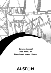
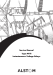
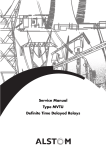
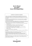
1
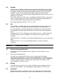
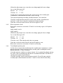
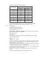
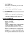
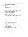
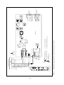
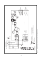
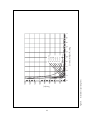
Service Manual
Type MWTU 11
Forward and Reverse Power Relay
Service Manual
Type MWTU 11
Forward and Reverse Power Relay
HANDLING OF ELECTRONIC EQUIPMENT
A person's normal movements can easily generate electrostatic potentials of several thousand volts.
Discharge of these voltages into semiconductor devices when handling electronic circuits can cause
serious damage, which often may not be immediately apparent but the reliability of the circuit will have
been reduced.
The electronic circuits of ALSTOM T&D Protection & Control Ltd products are immune to the relevant levels
of electrostatic discharge when housed in their cases. Do not expose them to the risk of damage by
withdrawing modules unnecessarily.
Each module incorporates the highest practicable protection for its semiconductor devices. However, if it
becomes necessary to withdraw a module, the following precautions should be taken to preserve the high
reliability and long life for which the equipment has been designed and manufactured.
1. Before removing a module, ensure that you are at the same electrostatic potential as the equipment
by touching the case.
2. Handle the module by its front-plate, frame, or edges of the printed circuit board.
Avoid touching the electronic components, printed circuit track or connectors.
3. Do not pass the module to any person without first ensuring that you are both at the same
electrostatic potential. Shaking hands achieves equipotential.
4. Place the module on an antistatic surface, or on a conducting surface which is at the same
potential as yourself.
5. Store or transport the module in a conductive bag.
More information on safe working procedures for all electronic equipment can be found in BS5783 and
IEC 60147-0F.
If you are making measurements on the internal electronic circuitry of an equipment in service, it is
preferable that you are earthed to the case with a conductive wrist strap.
Wrist straps should have a resistance to ground between 500k – 10M ohms. If a wrist strap is not
available, you should maintain regular contact with the case to prevent the build up of static.
Instrumentation which may be used for making measurements should be earthed to the case whenever
possible.
ALSTOM T&D Protection & Control Ltd strongly recommends that detailed investigations on the electronic
circuitry, or modification work, should be carried out in a Special Handling Area such as described in
BS5783 or IEC 60147-0F.
CONTENTS
SAFETY SECTION
5
1.
DESCRIPTION
9
2.
2.1
2.2
2.3
2.4
2.5
INSTALLATION
General
Relay mounting
Unpacking
Storage
Site
9
9
9
9
10
10
3.
3.1
3.1.1
3.2
3.3
3.3.1
3.3.2
3.3.3
3.4
3.5
3.6
3.7
3.8
3.8.1
3.8.2
3.8.2.1
3.8.3
3.8.4
3.8.5
3.8.6
3.8.7
3.8.8
3.8.9
COMMISSIONING
Commissioning preliminaries
Electrostatic discharge (ESD)
Wiring
Inspection
Removal of cover and case
Connections
Replace the module in the case and refit the cover.
Insulation
Earthing
Main current transformers
Commissioning equipment required
Commissioning tests
Calibrating phase shifter
Power settings (%Pn)
Commissioning procedure
Relay boundary
Instantaneous operating time
Reverse operation check
Time delayed operating time
DDO operation
Connecting relay to system
Replace any links, wiring fuses and remove any CT short circuits
10
10
10
10
10
11
11
11
11
11
11
11
12
12
12
13
13
13
14
14
15
16
16
4.
MAINTENANCE
16
5.
5.1
5.2
5.3
5.4
5.5
5.6
5.7
PROBLEM ANALYSIS
General
Visual examination of wiring
Gaining access to the relay internal circuits
Power supply pcb test
CT test
VT test
Measuring pcb (ZJ0250)
16
16
17
17
17
18
18
18
6.
Figure
Figure
Figure
Figure
Figure
Figure
SPARES
1. Application diagram for phase to phase reverse power connection
2. Application diagram for phase to neutral reverse power connection
3. Application diagram for phase to phase reverse VAR connection
4. Instantaneous operating times
5. Commissioning phase to phase connections
5. Commissioning phase to neutral connections
4
19
20
21
22
23
24
24
SAFETY SECTION
This Safety Section should be read before commencing any work on the equipment.
Health and safety
The information in the Safety Section of the product documentation is intended to
ensure that products are properly installed and handled in order to maintain them in
a safe condition. It is assumed that everyone who will be associated with the
equipment will be familiar with the contents of the Safety Section.
Explanation of symbols and labels
The meaning of symbols and labels which may be used on the equipment or in the
product documentation, is given below.
Caution: refer to product documentation
Caution: risk of electric shock
Protective/safety *earth terminal
Functional *earth terminal.
Note: this symbol may also be used for a protective/
safety earth terminal if that terminal is part of a
terminal block or sub-assembly eg. power supply.
*Note: The term earth used throughout the product documentation is the direct
equivalent of the North American term ground.
Installing, Commissioning and Servicing
Equipment connections
Personnel undertaking installation, commissioning or servicing work on this
equipment should be aware of the correct working procedures to ensure safety.
The product documentation should be consulted before installing, commissioning or
servicing the equipment.
Terminals exposed during installation, commissioning and maintenance may present
a hazardous voltage unless the equipment is electrically isolated.
If there is unlocked access to the rear of the equipment, care should be taken by all
personnel to avoid electric shock or energy hazards.
Voltage and current connections should be made using insulated crimp terminations
to ensure that terminal block insulation requirements are maintained for safety.
To ensure that wires are correctly terminated, the correct crimp terminal and tool for
the wire size should be used.
5
Before energising the equipment it must be earthed using the protective earth
terminal, or the appropriate termination of the supply plug in the case of plug
connected equipment. Omitting or disconnecting the equipment earth may cause a
safety hazard.
The recommended minimum earth wire size is 2.5 mm2, unless otherwise stated in
the technical data section of the product documentation.
Before energising the equipment, the following should be checked:
Voltage rating and polarity;
CT circuit rating and integrity of connections;
Protective fuse rating;
Integrity of earth connection (where applicable)
Equipment operating conditions
The equipment should be operated within the specified electrical and environmental
limits.
Current transformer circuits
Do not open the secondary circuit of a live CT since the high voltage produced
may be lethal to personnel and could damage insulation.
External resistors
Where external resistors are fitted to relays, these may present a risk of electric shock
or burns, if touched.
Battery replacement
Where internal batteries are fitted they should be replaced with the recommended
type and be installed with the correct polarity, to avoid possible damage to the
equipment.
Insulation and dielectric strength testing
Insulation testing may leave capacitors charged up to a hazardous voltage. At the
end of each part of the test, the voltage should be gradually reduced to zero, to
discharge capacitors, before the test leads are disconnected.
Insertion of modules and pcb cards
These must not be inserted into or withdrawn from equipment whilst it is energised,
since this may result in damage.
Fibre optic communication
Where fibre optic communication devices are fitted, these should not be viewed
directly. Optical power meters should be used to determine the operation or signal
level of the device.
6
Older Products
Electrical adjustments
Equipments which require direct physical adjustments to their operating mechanism to
change current or voltage settings, should have the electrical power removed before
making the change, to avoid any risk of electric shock.
Mechanical adjustments
The electrical power to the relay contacts should be removed before checking any
mechanical settings, to avoid any risk of electric shock.
Draw out case relays
Removal of the cover on equipment incorporating electromechanical operating
elements, may expose hazardous live parts such as relay contacts.
Insertion and withdrawal of extender cards
When using an extender card, this should not be inserted or withdrawn from the
equipment whilst it is energised. This is to avoid possible shock or damage hazards.
Hazardous live voltages may be accessible on the extender card.
Insertion and withdrawal of heavy current test plugs
When using a heavy current test plug, CT shorting links must be in place before
insertion or removal, to avoid potentially lethal voltages.
Decommissioning and Disposal
Decommissioning:
The auxiliary supply circuit in the relay may include
capacitors across the supply or to earth. To avoid electric
shock or energy hazards, after completely isolating the
supplies to the relay (both poles of any dc supply), the
capacitors should be safely discharged via the external
terminals prior to decommissioning.
Disposal:
It is recommended that incineration and disposal to water
courses is avoided. The product should be disposed of in a
safe manner. Any products containing batteries should have
them removed before disposal, taking precautions to avoid
short circuits. Particular regulations within the country of
operation,may apply to the disposal of lithium batteries.
7
Technical Specifications
Protective fuse rating
The recommended maximum rating of the external protective fuse for this equipment
is 16A, Red Spot type or equivalent, unless otherwise stated in the technical data
section of the product documentation.
Insulation class: IEC 61010-1:1990/A2: 1995 This equipment requires a
Class I
protective (safety) earth
EN 61010-1: 1993/A2: 1995 connection to ensure user
Class I
safety.
Installation
Category
(Overvoltage):
IEC 61010-1:1990/A2: 1995 Distribution level, fixed
Category III
installation. Equipment in
EN 61010-1: 1993/A2: 1995 this category is qualification
Category III
tested at 5kV peak, 1.2/50µs,
500Ω, 0.5J, between all supply
circuits and earth and also
between independent circuits.
Environment:
IEC 61010-1:1990/A2: 1995 Compliance is demonstrated by
Pollution degree 2
reference to generic safety
EN 61010-1: 1993/A2: 1995 standards.
Pollution degree 2
Product safety: 73/23/EEC
Compliance with the European
Commission Low Voltage
Directive.
EN 61010-1: 1993/A2: 1995 Compliance is demonstrated
EN 60950: 1992/A11:1997 by reference to generic safety
standards.
8
Section 1.
DESCRIPTION
The MWTU 11 is a single phase relay measuring Icosφ, where I is the current
flowing into the relay and φ is the phase angle between the current and voltage
vectors. MWTU 11 relays are suitable for power measurement on systems where the
system voltage is considered to be constant. With a balanced load, the single phase
MWTU 11 may be used to measure the three phase power of the system. This is
achieved by using a phase to neutral or phase to phase connection as indicated in
Figures 1 and 2 respectively. For measuring VARs in a system the MWTU 11 may be
used with a quadrature connection as shown in Figure 3.
The Icosφ detector provides an instantaneous output, the operation time of this
measuring unit varies with the relay setting and is given in Figure 4. The timer
incorporated within the relay may be set to start timing from either pick up or drop
off of the instantaneous element, this allows the MWTU 11 to be used for detecting
either overpower or underpower conditions.
A switch mode power supply is used to power the relay which is available in three
different voltage ranges, 24/54V, 48/125V and 110/250V dc. Setting of the relay
is achieved by a set of DIL switches on the front of the relay. These are calibrated to
give a setting range of 1% to 32.5% Pn in steps of 0.5% Pn, where Pn is equal to In
cosφ and a timer setting range of 0.25 to 32 seconds in steps of 0.25 seconds.
Section 2.
2.1
INSTALLATION
General
Protective relays, although generally of robust construction, require careful treatment
prior to installation and a wise selection of site. By observing a few simple rules the
possibility of premature failure is eliminated and a high degree of performance can
be expected.
2.2
Relay mounting
The relays are either despatched individually or as part of a panel/rack mounted
assembly in cartons specifically designed to protect them from damage.
Relays should be examined immediately they are received to ensure that no damage
has been sustained in transit. If damage due to rough handling is evident, a claim
should be made to the transport company concerned immediately and ALSTOM T&D
Protection & Control Ltd should be promptly notified. Relays which are supplied
unmounted and not intended for immediate installation should be returned to their
protective polythene bags.
2.3
Unpacking
Care must be taken when unpacking and installing the relays so that none of the
parts are damaged or their settings altered and must only be handled by skilled
persons.
Relays which have been removed from their cases should not be left in situations
where they are exposed to dust or damp. This particularly applies to installations
which are being carried out at the same time as construction work.
9
2.4
Storage
If relays are not installed immediately upon receipt they should be stored in a place
free from dust and moisture in their original cartons and where de-humidifier bags
have been included in the packing they should be retained. The action of the dehumidifier crystals will be impaired if the bag has been exposed to ambient
conditions and may be restored by gently heating the bag for about an hour, prior to
replacing it in the carton.
Dust which collects on a carton may, on subsequent unpacking, find its way into the
relay; in damp conditions the carton and packing may become impregnated with
moisture and the de-humidifying agent will lose its efficiency.
The storage temperature range is –25˚C to +70˚C.
2.5
Site
The installation should be clean, dry and reasonably free from dust and excessive
vibration. The site should preferably be well illuminated to facilitate inspection.
An outline diagram is normally supplied showing panel cut-outs and hole centres.
For individually mounted relays these dimensions will also be found in publication
R6127.
Publication R7012, Parts Catalogue and Assembly Instructions, will be useful when
individual relays are to be assembled as a composite rack or panel mounted
assembly.
Publication R6001 is a leaflet on the modular integrated drawout system of protective
relay.
Publication R6014 is a list of recommended suppliers for the pre-insulated
connectors.
Section 3.
3.1
COMMISSIONING
Commissioning preliminaries
Check that ratings of relay agree with the supplies to which the relay is to be
connected.
3.1.1
Electrostatic discharge (ESD)
The relay uses components which are sensitive to electrostatic discharges.
When handling the withdrawn module, care should be taken to avoid contact with
components and electrical connections. When removed from its case for storage the
module should be placed in an electrically conducting anti-static bag. See full
recommendations inside front cover.
3.2
Wiring
Check all wiring connections to the relay, including the case earthing connection
above the terminal block. The relay diagram number appears inside the case.
3.3
Inspection
Before leaving the factory all relays are accurately adjusted, tested and carefully
packed. Hence there should be no need for any re-adjustment on commissioning.
10
3.3.1
Removal of cover and case
To gain access to the relay, first loosen the captive cover screws. Then carefully
remove the cover from the case.
The module can then be removed from the case by grasping the handles at the top
and bottom of the front plate and pulling forwards.
Care must be taken to ensure that mechanical settings of the element are not
disturbed.
3.3.2
Connections
Examine wiring connections and major components and ensure that there is no
obvious mechanical damage. Do not adjust trimpots on the PCB.
3.3.3
Replace the module in the case and refit the cover. Make sure that the reset
mechanism in the cover is correctly located and that the LED indicator or flag can be
reset.
3.4
Insulation
The relay and its associated wiring may be insulation tested between:
• all electrically isolated circuits
• all circuits and earth
An electronic or brushless insulation tester should be used, having a dc voltage not
exceeding 1000V. Accessible terminals of the same circuit should first be strapped
together. Deliberate circuit earthing links, removed for the tests, subsequently must be
replaced.
3.5
Earthing
Ensure that the case earthing stud is used to connect the relay to a local earth bar.
3.6
Main current transformers
Do not open the secondary circuit of a live CT since the high voltage produced may
be lethal to personnel and could damage insulation.
3.7
Commissioning equipment required
Phase shifting transformer
Variable current source
Wattmeter
Ammeter 0 – 10A ac
Voltmeter 0 – 150V ac
Phase angle meter (optional)
Timer 0 – 100 seconds
Note:
Accurate testing of the relay near the boundaries (±90° from RCA) may not
be satisfactory using the calibrated marks on the phase shifting transformer.
We therefore recommend that a wattmeter or phase angle meter is used to
test the relay near the boundary. It is also essential that stable low harmonic
content current and voltage sources are used.
Connections to the relay are shown in Figures 5 and 6 (for phase to phase and
phase to neutral respectively).
11
3.8
Commissioning tests
Set switch %Pn to 1%.
Set timer control to 0.25 seconds.
Set DPU/DDO switch to DPU.
Connect the relay as shown in Figures 5 and 6 (phase to neutral or phase to phase
connection) as appropriate.
Apply rated Vn and In.
Apply rated Vx.
Where the relay range covers more than one voltage apply the lowest voltage.
The values of Vn, In and Vx are marked on the front of the relay.
Check the green POWER LED illuminates when the auxiliary voltage (Vx) is applied to
the relay.
3.8.1
Calibrating phase shifter
The following is only necessary if a phase meter is not used.
Adjust the phase shifter to give maximum reading on the wattmeter.
Set the phase shifter pointer to indicate 0°.
Adjust the phase shifter to give minimum reading on the wattmeter and readjust the
pointer if necessary to indicate 90°.
Set the phase shifter to zero degrees, the voltage and current inputs are now in
phase and the system set to unity power factor (UPF). This coincides with the relay
characteristic angle (RCA) of 0°.
3.8.2
Power settings (%Pn)
Current settings at UPF in mA.
Apply rated Vn.
Apply rated Vx.
Where the relay range covers more than one voltage apply the lowest voltage.
The operate current is measured for each switch setting given in the table below by
first injecting the minimum current and checking that the instantaneous element does
not pick up after 60 seconds, then injecting the maximum current and checking the
output element operates within 60 seconds.
12
3.8.2.1 Commissioning procedure
%Pn
Current = 1
Current = 5
Operating current in mA
Operating current in mA
nominal
minimum
maximum
nominal
minimum
maximum
1
10
8.00
12.00
50
40.00
60.00
1.5
15
13.00
17.00
75
65.00
85.00
2
20
18.00
22.00
100
90.00
110.00
3
30
28.00
32.00
150
140.00
160.00
5
50
48.00
52.00
250
240.00
260.00
9
90
87.30
92.70
450
436.50
463.50
17
170
164.90
175.10
850
824.50
875.50
32.5
325
315.25
334.75
1625
1576.25
1673.75
Setting limits are ±3% of the nominal values, or ±2mA for In = 1A and ±10mA for
In = 5A, whichever is the greater.
The relay should reset at a current level greater than 97% of pick-up.
3.8.3
Relay boundary
Apply rated Vn and In
Apply rated Vx.
Where the relay range covers more than one voltage apply the lowest voltage.
With the power setting as given in the following table, the phase angle between the
current and voltage vectors is varied to give the lead and lag phase angle
boundaries for the instantaneous unit to operate with rated current applied.
Note:
Adjust phase shifter SLOWLY into the operating zone until the relay operates.
Power setting
%Pn
3.8.4
Nominal boundary
from RCA
Tolerance
3
±88.3°
30
±72.5°
±1.5° or ±15% of the
nominal Icosφ value
whichever is the greater.
Instantaneous operating time
Set power setting %Ps to 16%.
Check the relay is connected as indicated in Figures 5 and 6 for phase to phase or
phase to neutral connections as applicable.
Apply rated Vn and In.
Apply rated Vx.
13
Where the relay range covers more than one voltage apply the lowest voltage.
Set I to the following at UPF:
for
In = 1A
1500mA for
In = 5A
480mA
Set the timer to measure the time from the switch closing to the normally open
instantaneous contact between terminals 2 and 4 closing.
The measured operating time delay should be between 10ms and 40ms.
Check the contact between terminals 4 and 6 open and the contact between
terminals 1 and 5 closes when the instantaneous element operates.
Open the switch at the end of the test and set all supplies to zero.
3.8.5
Reverse operation check
Reverse the connections to terminals 27 and 28 on the relay to give a 180° phase
reversal.
Apply rated Vn and In.
Apply rated Vx.
Where the relay range covers more than one voltage, apply the lowest voltage.
Set I to the following at UPF:
480mA
for
In = 1A
1500mA
for
In = 5A
Close the switch. Check that the relay does not operate.
Open the switch at the end of the test and set all supplies to zero.
Reverse the connections to terminals 27 and 28 on the relay.
3.8.6
Time delayed operating time
Set the timer to measure the time between the normally open instantaneous contacts
between terminals 2 and 4 closing and the normally open time delayed contacts
between terminals 17 and 19 closing.
Using the same test conditions as given in Section 3.8.4, operate the relay by closing
the switch. After a time delay the red TRIP LED should be illuminated. The TRIP LED is
reset by pressing the reset push button.
Check the normally closed contact between terminals 19 and 20 opens and the
normally open contact between terminals 15 and 16 closes after the time delay.
14
Check the time delay for the following settings:
Set time delay
Operating time (seconds)
Minimum
Maximum
0.25
0.20
0.30
0.5
0.45
0.55
1.0
0.95
1.05
1.5
1.425
1.575
2.5
2.375
2.625
4.5
4.275
4.725
8.5
8.075
8.925
16.5
15.675
17.375
The operating time delay tolerance is ±5% or 50ms whichever the greater.
Open the switch at the end of the test and set all supplies to zero.
3.8.7
DDO operation
Set the DPU/DDO switch to DDO.
Set the operating time to 4.5 seconds.
Set power setting %Pn to 16%.
Check the relay is connected as indicated in Figures 5 and 6 for phase to phase or
phase to neutral connections as applicable.
Apply rated Vn and In.
Apply rated Vx.
Where the relay range covers more than one voltage apply the lowest voltage.
Set I to the following at UPF:
480mA
for
In = 1A
1500mA
for
In = 5A
Set the timer to measure the time between the normally open instantaneous contacts
between terminals 2 and 4 opening and the normally open time delayed contacts
between terminals 17 and 19 closing.
With the switch open, the timer should time out and the normally open time delayed
contact between terminals 17 and 19 should be closed.
Close the switch to reset the MWTU 11 timer delay circuit. The time delayed contact
between terminals 17 and 19 should open.
Open the switch, check the measured time delay is between 4.275 and 4.725
seconds.
Open the switch at the end of the test and set all supplies to zero.
15
3.8.8
Connecting relay to system
Connect the relay to the system as shown in the application diagrams
(10 MWTU11 01 sheets 1, 2 and 3).
Apply the required power setting %Pn and time delay setting, including setting the
time delay to DPU or DDO as required.
Check the instantaneous contacts close when power flows in the direction indicated
on the application diagram.
Check the time delayed output contacts close and the TRIP indicator illuminates when
the time delay circuit operates as set by DPU/DDO switch.
3.8.9
Replace any links, wiring fuses and remove any CT short circuits used during
commissioning.
Section 4.
MAINTENANCE
Periodic maintenance is not necessary. However, periodic inspection and test is
recommended.
Routine testing of the relay can be performed by the secondary injection method, as
detailed in the commissioning instructions.
As a minimum test, the relay should be routinely checked to ensure the green POWER
LED is illuminated. This LED indicates the auxiliary supply is present on the relay
terminals and the internal power supply is operational.
Section 5.
5.1
PROBLEM ANALYSIS
General
These instructions enable a fault to be located to sub-assembly level, fault finding to
component level is not recommended.
The major reasons for this are as follows:
– Fault finding on printed circuit boards (PCBs) requires specialised knowledge and
equipment.
– Components used in manufacture are subjected to strict quality control procedures
and in certain cases selected for a particular characteristic. Metal oxide
semiconductors (MOS) components used require very careful handling.
– Damage can be caused to printed circuit board track unless extreme care is used
in replacement of components.
– Replacement of certain components will require recalibration of the relay.
In the event of a faulty sub-assembly being found, it is recommended that the relay is
returned to ALSTOM T&D Protection & Control Ltd or sent to a competent service
centre for the work to be carried out. However, replacement sub-assemblies can be
made available from ALSTOM T&D Protection & Control Ltd on request, provided the
relay model number and serial number are quoted.
When investigating any faults on the relay full ESD precautions, including wearing an
earthed wrist strap must be observed. Refer to the instructions inside the front cover of
this manual.
16
When a PCB is removed from the module it should be immediately placed in an antistatic bag. Under no circumstances should the PCBs be placed in plastic bags or on
a plastic surface.
If the measuring PCB is replaced it will be necessary to recalibrate the complete
relay.
5.2
Visual examination of wiring
Ensure that all the push-on blades to the rear terminal block are in position.
Ensure that all the connectors to the PCB are in position and pushed fully hoe.
Note:
The large wirewound resistors at the top of the PCB ZJ0250 are not fitted to
the VAR versions of the MWTU 11.
Check all the PCB interconnecting plugs and sockets are making correctly.
5.3
Gaining access to the relay internal circuits
Where required the following method is used to gain access to the internal circuits of
the module.
The method for removing the front plate is to remove the four pozidrive screws from
the black front plate which will then release the front plate from the relay module.
To remove the measuring PCB, first disconnect all the connectors plugged into the
side of the measuring PCB, the PCB may then be gently eased forward taking care
not to stress the rear PCB to PCB connectors. When the measuring PCB is replaced,
care should be taken to ensure the rear mounted connectors align before fully
pushing the measuring PCB home.
The measuring PCB may now be pulled forward.
5.4
Power supply PCB test
This section is to check the power supply consisting of the backplane PCB ZJ0300
and the backplane daughter PCB ZJ0228 operate correctly.
With the measuring PCB still in the module, apply rated dc auxiliary voltage to
terminal 13(+) and 14(–). Use a high impedance dc voltmeter to check the voltages
measure on PL2 of the backplane power supply PCB are as follows:
Measure voltage between terminals
on PCB ZJ0300 - PL2
Approximate voltage (V)
PL2-6 to PL2-8
+15V
PL2-5 to PL2-8
+5V
PL2-10 to PL2-8
–15V
Note:
Care should be taken to ensure that no short circuits to other connector
terminals are made inadvertently when connecting the voltmeter to the
required terminals, as this could result in damage to the relay.
Pin 1 of PL2 is to the top of the PCB.
The measuring PCB should always be in position when power is applied to
the relay.
17
If any of the voltages are not present or are very low, a fault is present on the power
supply back plane or daughter PCB. In this instance both the backplane PCB ZJ0300
and daughter PCB ZJ0228 should be replaced.
5.5
CT test
A suitable connector will be required for this test to allow connections to be made to
PL8.
Check all supplies are off.
Unplug PL8 from the PCB, this is the connection from the torroidal current transformer.
Connect an ammeter between the yellow and blue wires to PL8.
Apply rated current (In) to terminals 27 and 28.
Do not apply auxiliary voltage (Vx) or measured voltage (Vn) to the relay.
The reading obtained on the ammeter should be 2.5mA.
Switch off the ac current supply to the relay.
Change the ammeter connections to measure the current between the yellow and
green wires.
Apply rated current (In) to terminals 27 and 28.
Do not apply auxiliary voltage (Vx) or measured voltage (Vn) to the relay.
The reading obtained on the ammeter should be 5mA.
Switch off the ac current supply to the relay.
5.6
VT test
A suitable connector will be required for this test to allow connections to be made to
PL7.
Check all supplies are off.
Unplug PL7 from the measuring PCB ZJ0250. This is the connection to the voltage
transformer.
Connect a voltmeter between the red and black wires.
Apply rated voltage (Vn) to terminals 21 and 22.
Do not apply auxiliary voltage (Vx) or current (In) to the relay.
The reading obtained on the voltmeter should be approximately 38V.
Switch off the voltage supply to the relay.
5.7
Measuring PCB (ZJ0250)
Use a phase to phase connection as shown in Figure 5.
Apply the phase to neutral voltage Vn to terminals 21 and 22.
Measuring the voltage across the 12W wirewound resistors, this should be
approximately Vn.
18
Section 6.
SPARES
When ordering spares, quote the full relay model number and any component
reference numbers.
PCB numbers are marked on the component side of the PCB and consist of the PCB
number printed on the silk screen followed by the PCB part number written after the
pcb number.
Transformer numbers can be found on the side of torroidal transformers or on the
laminations of shell transformers.
Should the need arise for the equipment to be returned to ALSTOM T&D Protection &
Control Ltd for repair, then the form at the back of this manual should be completed
and sent with the equipment. A copy of any commissioning test results should also be
sent with the equipment.
19
20
14
16
13
15
a
Figure 1.
b
c
C
S2
(b)
(c)
(d)
Notes:
1. (a)
28
21
27
–VE
+VE
N
L
14
13
10
9
8
25
22
VN 23
IN
C
B
A
Power
supply
circuits
Case earth connection
C
B
Phase rotation
A
CT shorting links make
before (b) and (c) disconnect.
Short terminals break before (c).
Long terminal.
Pin terminal (PCB type).
VX
VAC
(See note 4)
(See note 2)
S1
P1
Vref
a f(a>b)
b
4. Earthing connections (CTs) are typical only.
3. VT connections are typical only.
2. CT connections are typical only.
Power
Phase
sensitive
bridge
PS
Application diagram for phase to phase reverse power connection
Module terminal block
viewed from rear
27
25
28
22
21
23
20
19
17
10
8
6
4
2
9
5
1
Case earth
(See note 3)
A B
P2
Direction of power flow for
instantaneous relay operation
MWTU 11
RL1
2
Reset
t
Reset
Op
RL2–2
RL2–1
RL1–2
RL1–1
RL3
1
RL2
2
Trip
16
15
19
17
20
5
1
4
2
6
Time-delayed
contacts
Instantaneous
contacts
21
2
14
16
13
15
Figure 2.
S2
(b)
(c)
(d)
Notes:
1. (a)
N
C
B
A
28
21
27
–VE
+VE
N
L
14
13
10
9
8
25
VN 22
23
IN
P1
Power
supply
circuits
Case earth connection
C
B
Phase rotation
A
CT shorting links make
before (b) and (c) disconnect.
Short terminals break before (c).
Long terminal.
Pin terminal (PCB type).
VX
VAC
(See note 4)
(See note 2)
S1
Vref
a f(a>b)
b
4. Earthing connections (CTs) are typical only.
3. VT connections are typical only.
2. CT connections are typical only.
Power
Phase
sensitive
bridge
PS
Application diagram for phase to neutral reverse power connection
Module terminal block
viewed from rear
27
25
28
22
21
23
20
19
17
10
8
6
4
9
5
1
Case earth
(See note 3)
A
a
N
n
P2
Direction of power flow for
instantaneous relay operation
MWTU 11
RL1
2
Reset
t
Reset
Op
RL2–2
RL2–1
RL1–2
RL1–1
RL3
1
RL2
2
Trip
16
15
19
17
20
5
1
4
2
6
Time-delayed
contacts
Instantaneous
contacts
22
b
c
2
14
16
13
15
Figure 3.
S2
(b)
(c)
(d)
Notes:
1. (a)
–VE
+VE
N
L
VN
IN
C
B
A
14
13
10
9
8
22
28
21
27
Power
supply
circuits
Case earth connection
C
B
Phase rotation
A
CT shorting links make
before (b) and (c) disconnect.
Short terminals break before (c).
Long terminal.
Pin terminal (PCB type).
VX
VAC
(See note 4)
(See note 2)
S1
P1
Vref
a f(a>b)
b
4. Earthing connections (CTs) are typical only.
3. VT connections are typical only.
2. CT connections are typical only.
Power
Phase
sensitive
bridge
PS
Application diagram for phase to phase reverse VAR connection
Module terminal block
viewed from rear
27
25
28
22
21
23
20
19
17
10
8
6
4
9
5
1
Case earth
(See note 3)
B
C
P2
Direction of power flow for
instantaneous relay operation
MWTU 11
RL1
2
Reset
t
Reset
Op
RL2–2
RL2–1
RL1–2
RL1–1
RL3
1
RL2
2
Trip
16
15
19
17
20
5
1
4
2
6
Time-delayed
contacts
Instantaneous
contacts
23
Figure 4.
0
200
400
600
800
1,000
1,200
1,400
1,600
0
Instantaneous operating times
Time (ms)
2
4
6
10
12
14
Current as multiple of Ps setting
8
Ps = 32.5%
Ps = 16%
Ps = 10%
Ps = 5%
Ps = 3%
Ps = 1%
16
18
20
13
Auxiliary
voltage
Current
source
14
N
28
A
A
27
W
MWTU 11
Timer
start
Voltage
source
a
b
c
A
B
C
21
23
25
n
N
2
Timer
stop
4
Note: Check that Vab = Vbc = Vca = Vn (2%)
and note that a 5% variation in phase-to-phase volts may
incur an additional 2° error in phase angle measurement.
Figure 5.
Commissioning phase to phase connections
Auxiliary
voltage
Current
source
13
14
28
N
A
A
27
W
Timer
start
Voltage
source
MWTU 11
A
B
C
a
b
c
N
n
21
22
Timer
stop
Figure 5.
Commissioning phase to neutral connections
24
2
4
Section 7.
Date
COMMISSIONG INSTRUCTIONS
_____________________________________
Station _____________________________________
Circuit ___________________________
Relay Model No. ____________________________
Serial No. _______________________
Vn _________________
V
Vx ________________ V
Time delay ________________
In _________________
A
Setting _____________ %Pn
Frequency _______________ Hz
DPU or DDO _______________________
TESTS
3.4
Insulation
3.8
Power indicator
3.8.2
Current sensitivity at RCA
3.8.3
3.8.4
%Pn
mA
1
___________________________
1.5
___________________________
2
___________________________
3
___________________________
5
___________________________
9
___________________________
17
___________________________
32.5
___________________________
Boundary
Setting
Degrees lead
Degrees lag
3%
____________________
______________________
30%
____________________
______________________
Instantaneous operating time ________________________________
Instantaneous contacts ______________________________________
3.8.5
Reverse operation check ____________________________________
25
3.8.6
Time delayed operating time
Time setting
Operate time
0.25
______________________________
0.50
______________________________
1
______________________________
1.5
______________________________
2.5
______________________________
4.5
______________________________
8.5
______________________________
16.5
______________________________
Time delayed contacts
______________________________
3.8.7
DDO operating time
______________________________
2.8.6
System connections
______________________________
2.8.7
Relay settings
______________________________
%Pn
______________________________
time delay
______________________________
DPU/DDO
______________________________
Commissioning Engineer
Customer Witness
Company
Company
Date
Date
26
REPAIR FORM
Please complete this form and return it to ALSTOM T&D Protection & Control Ltd with the
equipment to be repaired. This form may also be used in the case of application queries.
ALSTOM T&D Protection & Control Ltd
St. Leonards Works
Stafford
ST17 4LX,
England
For:
After Sales Service Department
Customer Ref:
_______________________
ALSTOM Contract Ref: _______________________
Date:
1.
Model No: _____________________
Serial No:
_____________________
_______________________
What parameters were in use at the time the fault occurred?
AC volts
_____________ Main VT/Test set
DC volts
_____________ Battery/Power supply
AC current
_____________ Main CT/Test set
Frequency
_____________
2.
Which type of test was being used? ____________________________________________
3.
Were all the external components fitted where required?
(Delete as appropriate.)
4.
List the relay settings being used
Yes/No
____________________________________________________________________________
____________________________________________________________________________
____________________________________________________________________________
5.
What did you expect to happen?
____________________________________________________________________________
____________________________________________________________________________
____________________________________________________________________________
____________________________________________________________________________
continued overleaf
✁
27
6.
What did happen?
____________________________________________________________________________
____________________________________________________________________________
____________________________________________________________________________
____________________________________________________________________________
7.
8.
When did the fault occur?
Instant
Yes/No
Intermittent
Yes/No
Time delayed
Yes/No
(Delete as appropriate).
By how long?
___________
What indications if any did the relay show?
____________________________________________________________________________
____________________________________________________________________________
____________________________________________________________________________
9.
Was there any visual damage?
____________________________________________________________________________
____________________________________________________________________________
____________________________________________________________________________
10. Any other remarks which may be useful:
____________________________________________________________________________
____________________________________________________________________________
____________________________________________________________________________
______________________________________
Signature
_______________________________________
Title
______________________________________
Name (in capitals)
_______________________________________
Company name
✁
28
29
30
31
A L S T O M T & D P r o t e c t i o n & C o n t r o l L t d St Leonards Works, Stafford, ST17 4LX England
Tel: 44 (0) 1785 223251 Fax: 44 (0) 1785 212232 Email: [email protected] Internet: www.alstom.com
©1999 ALSTOM T&D Protection & Control Ltd
Our policy is one of continuous product development and the right is reserved to supply equipment which may vary from that described.
Publication R8127B
Printed in England.