1
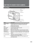
-J04811
REV. 2015-04-14
XL STOP/TAIL/TURN SIGNAL AND LICENSE PLATE RELOCATION
KIT
GENERAL
Kit Number
To prevent accidental vehicle start-up, which could cause
death or serious injury, remove main fuse before proceeding. (00251b)
73279-10
Models
For model fitment information, see the P&A retail catalog or
the Parts and Accessories section of www.harley-davidson.com
(English only).
2.
Refer to the service manual and follow the instructions
given to remove the main fuse.
3.
Follow the service manual instructions to remove the seat.
Additional Parts Required
4.
Raise the rear of the vehicle to relieve the load on the
shock absorbers.
5.
Follow the service manual instructions to remove only the
bottom end shock absorber fasteners on each side of the
vehicle. Save the fasteners for later assembly.
This kit is needed in order to complete the installation of
saddlebag kits on specific model motorcycles. See the P&A
retail catalog or the Parts and Accessories section of
www.harley-davidson.com (English only) for available
saddlebag kits, model fitment information and additional part
requirements.
Tools and Supplies Required
The help of an assistant will be needed for some removal
and installation procedures.
A terminal pick (Snap-On® TT600-3 or equivalent) will aid in
the installation of this kit.
Loctite® 271 Threadlocker and Sealant - Red (H-D Part No.
99671-97) is required for the proper installation of this kit.
NOTE
Upper end shock absorber fastener removal may be required
for installation of specific saddlebags. Refer to the instructions
found with the saddlebags for further information.
6.
Electrical Disconnection
1.
Electrical Contact Lube (H-D Part No. 99861-02) or equivalent
is required for the proper installation of this kit.
The rider's safety depends upon the correct installation
of this kit. Use the appropriate service manual procedures.
If the procedure is not within your capabilities or you do
not have the correct tools, have a Harley-Davidson dealer
perform the installation. Improper installation of this kit
could result in death or serious injury. (00333a)
NOTE
This instruction sheet refers to service manual information. A
service manual for this year/model motorcycle is required for
this installation and is available from a Harley-Davidson dealer.
Kit Contents
See Figure 5 and Table 1.
INSTALLATION
Raise the rear of the vehicle further to allow access to the
underside of the rear fender.
Unclip the ECM from the electrical caddy per service
manual instructions with the following exception:
a.
Unplugging the ECM wiring harness connector [78B]
from the ECM is not required. Electrical connectors
are identified in the service manual by the number
and letter within brackets.
Gently lay the ECM to the left side to expose the fourway stop/tail/turn signal (STT) connectors [18] and
[19] and two-way license plate illuminator connector
[40] beneath.
2.
Identify and clearly label the left and right STT harnesses
on the vehicle side of the harness connections.
NOTE
Make note of the wire colors and cavity locations before
removing the terminals from the socket housings on the lamp
side of the harness connections.
3.
Remove the wires and socket terminals from the STT
socket housings [18B] and [19B]. Remove the wires and
socket terminals from the license plate illuminator socket
housing [40B].
Set the socket housings aside for later installation.
Preparation
1.
Position the vehicle on a motorcycle lift under the frame
so the vehicle is upright and level.
-J04811
Many Harley-Davidson® Parts & Accessories are made of plastics and metals which can be recycled.
Please dispose of materials responsibly.
1 of 8
Rear Fender, Lamp and License Bracket Removal
NOTE
6.
Get the rear reflector (10) from the kit.
7.
Clean the reflector mounting area of the license bracket
with a mixture of 50-70% isopropyl alcohol and 30-50%
distilled water. Allow to dry thoroughly.
The reflector mounting block is held to the fender with double
sided tape. Take care during removal to avoid scratching paint.
1.
Remove the rear reflector and mounting block from the
underside of the rear fender.
Remove any residual adhesive from the underside of the
fender.
2.
NOTE
Ambient temperature should be at least 60 °F (16 °C) for
proper adhesion of the reflector to the bracket.
8.
Remove the license plate from the vehicle (if installed).
Retain the plate and attaching hardware.
NOTE
Note the location and orientation of rear fender mounting
hardware, and save for later assembly.
3.
4.
Refer to the service manual and follow the instructions
given to remove and disassemble the rear fender and
license plate bracket, with the following exceptions:
a.
The fender will not be completely removed from the
vehicle.
b.
Rear wheel elevation and removal is not necessary.
c.
ECM caddy and rear fender extension removal are
not required. The seat post needs only to be
loosened, not removed.
Remove the liner from the adhesive backing of the
reflector. Carefully position the reflector, centered both
horizontally and vertically, to the reflector mounting area
of the bracket, and press firmly into place. Hold the
reflector in position with steady pressure for about one
minute.
NOTE
Allow AT LEAST 24 hours after applying the reflector before
exposing the area to vigorous washing, strong water spray or
extreme weather.
The adhesive bond will increase to maximum strength after
about 72 hours at normal room temperature.
is06265
Have an assistant raise or lower the fender to allow access
to the two rearmost rivets on the left side of the vehicle.
Drill out the rivets on the left side only to remove the
license plate bracket mount assembly.
8
7
6
Remove the license plate illuminator from the license plate
bracket mount assembly. Save the illuminator.The bracket
mount and screws can be discarded.
See Figure 5. Get the new license plate bracket (5), illuminator cover (6), spacer (8) and two M4 screws (7) from
the kit, and the license plate illuminator (A):
•
Removed from the original equipment (OE) license plate
bracket on US models only.
•
Purchased separately on all other models.
2.
See Figure 1. Assemble the illuminator (1), spacer (2) and
cover (3) to the license plate bracket (5) in the sequence
shown, and tighten the screws (4) securely.
3.
Get the STT relocation weldment (6), two screws (7) and
two flat washers (8) from the kit.
4.
Apply a few drops of Loctite 271 - Red to the clean screw
threads.
Assemble the license plate bracket to the weldment as
shown, and tighten the screws to 120 in-lbs (13.6 N-m).
NOTE
If using a metal tool to install the black nuts, protect the finish
with cloth or paper to prevent damage.
5.
5
4
1
License Bracket Assembly
1.
11
3
NOTE
Take care when disengaging the license plate illuminator harness from the license plate bracket mount and fender.
5.
9
2
1.
2.
3.
4.
5.
6.
7.
8.
9.
10.
11.
10
License plate illuminator
Spacer
Illuminator cover
Button head screw (2)
License plate bracket
STT relocation weldment
Hex head screw (2)
Flat washer (2)
Black painted nut (2)
Rear reflector
License plate bracket square hole
Figure 1. License Plate Illuminator Installation
Rear Lamp Wiring
1.
Remove the STT lamps from the rear fender support
covers per service manual instructions.
NOTE
If necessary, apply a light coat of liquid soap, window cleaner
or all-purpose lubricant to the license plate illuminator wire
ends and conduit. Use a fish tape or mechanics' wire if needed
to guide the wires through the tube.
Loosely install the black painted nuts (9) onto the threaded
studs on each side of the STT relocation weldment.
-J04811
2 of 8
2.
3.
See Figure 1. Feed the license plate illuminator wire conduit through the square hole (11) on the left side of the
license plate bracket.
See Figure 5. Guide the wire and conduit into the hole (C)
in the STT relocation weldment (1) tube, and push the
wires past the Y-joint (D) on the left side of the tube.
4.
Get three new terminated wires, one black (12), one violet
(11) and one blue (10) from the kit.
5.
Feed the unterminated end of one wire into the left-side
threaded stud (E) on the STT relocation weldment. Guide
the wire into the tube, and push the wires past the Y-joint.
6.
7.
is05961a
8
16
10 11 12
15
13
9
17
6
1
4
11
10
2
Feed the unterminated end of the second wire into the
threaded stud, favoring the inside of the curve. Guide both
wires and the license plate illuminator wire conduit into
the tube until the second wire gets past the Y-joint.
7
5
12
3
Feed the unterminated end of the third wire into the
threaded stud, favoring the inside of the curve. Guide all
the wires and conduit into the tube until the first wire end
comes out through the left forward opening (F) of the tube.
1.
2.
3.
4.
5.
6.
7.
8.
9.
10.
11.
12.
13.
14.
15.
16.
17.
Continue pulling and pushing the wires until all the wire
ends are exposed.
8.
14
Pull the license plate illuminator wire conduit through the
tube until the slack is taken up at the license plate bracket.
Pull a small amount of slack back as wire relief.
Use a cable strap (not provided) to bind the license plate
illuminator wire conduit to the STT relocation weldment
near hole (C).
Housing
Lens
Bulb
Gasket
Reflector
Bulb socket
Spring
Unthreaded hole
Threaded hole
Black wire
Violet wire
Blue wire
Protective tubing
Recess cover
Lockwasher
Jam nut
Hole in bulb socket cavity
Figure 2. Stop/Tail/Turn Signal Lamp (Right Side Shown)
9.
See Figure 2. Insert the blade of a small screwdriver into
the slot at the bottom of the lens (2) of the left-side STT
lamp, and twist to unsnap the lens from the housing (1).
Push the bulb (3) in and rotate counterclockwise to
remove. Set the lens and bulb aside for later installation.
NOTE
Make note of the cavity location and color of each wire in the
reflector bulb socket (6) before removing. The violet wire (11)
should be closest to the locating tab on the bulb socket. New
wires from the kit must be installed in the same cavities.
10. Note the location and color of the two wires in the reflector
bulb socket (6). Slide the bulb socket and spring (7) from
the reflector (5). Remove the wires and button terminals
from the bulb socket.
11. Insert a right-angle pick or a 7/64 (3 mm) hex key into the
bulb socket cavity, hooking into the hole (17). Pull the
reflector free of the lamp housing.
Separate the rubber gasket (4) from the reflector or
housing.
12. Remove the ground terminal and black wire (10) from the
back of the reflector.
Guide the protective tubing (13) with all three wires out of
the unthreaded hole (8) in the lamp housing, and discard.
-J04811
3 of 8
NOTE
Be sure the recess cover, lockwasher and jam nut have been
installed in the exact orientation and sequence shown before
feeding the wiring through the stop/tail/turn signal housing.
13. Place a lockwasher (15) onto the left-side threaded stud,
against the jam nut (16) already installed on the STT
relocation weldment. Place a black recess cover (14), in
the orientation shown, onto the stud.
14. Insert the wires from the left-side threaded stud on the
STT relocation weldment through the threaded hole (9)
in the lamp housing (1) and the center of the rubber gasket
(4).
15. Screw the lamp housing onto the stud. Be careful that the
wires are not twisted or damaged as the weldment stud
and lamp are assembled. Align the recess cover over the
holes and recess in the lamp housing. The lockwasher
will fit inside the hole in the recess cover.
19. Slide one piece of protective tubing over the three STT
lamp wires and into the forward opening (F) of the STT
relocation weldment on each side. Continue sliding the
tubing over the wires until it reaches at least as far as the
Y-joint, or preferably all the way to the STT lamp housing.
20. Repeat steps 4 through 19 for the right-side STT lamp.
Rear Fender, Lamp and License Bracket Installation
1.
See the Figure 5 top inset. Get the left-side reflector
mounting bracket (22) and pop rivets (23) from the kit.
Position the bracket to the inside left of the fender, aligning
the mounting holes with the holes in the fender from the
drilled-out rivets. Refer to the similar bracket on the right
side.
2.
Install the bracket to the fender, inserting the pop rivets
from the outside of the fender.
3.
For US models only:
Align the lamp housing so that the lens will be aimed
rearward and parallel to the ground. While holding the
housing in position, hand tighten the jam nut against the
lockwasher.
Ambient temperature should be at least 60 °F (16 °C) for
proper adhesion of the reflector to the bracket.
16. Insert the terminal of the new black wire (10) into the cavity
in the rear of the reflector (5) until it clicks into place.
Thread the blue wire (12) and violet wire (11) through the
center of the reflector (5), and the spring (7), and insert
the button terminals into the correct slots and cavities in
the reflector bulb socket (6).
a.
Get the rear reflector (L), purchased separately.
b.
Clean the reflector mounting area of the bracket with
a mixture of 50-70% isopropyl alcohol and 30-50%
distilled water. Allow to dry thoroughly.
c.
Remove the liner from the adhesive backing of the
reflector. Carefully position the reflector, centered
both horizontally and vertically, to the reflector
mounting area of the bracket, and press firmly into
place. Hold the reflector in position with steady pressure for about one minute.
17. Assemble the lamp as follows:
a.
Insert the spring and bulb socket back into the
reflector, aligning the tab on the socket with the slot
in the reflector.
b.
Seat the reflector assembly in the rubber gasket,
aligning the tab on the reflector with the slot in the
gasket.
c.
Install the reflector assembly, aligning the tab on the
reflector with the slot inside the lamp and leaving
about 1-2 inches (50-100 mm) of wire inside the lamp
housing.
Carefully pull the individual wires at the front opening
of the STT weldment to remove excess wire from
inside the tube.
d.
Using the thumbs of both hands, apply even pressure
around the outer edge of the reflector assembly until
fully seated.
e.
Liberally apply electrical contact lubricant (H-D Part
No. 99861-02) or equivalent to the contacts in the
reflector socket and at the base of the bulb. Push in
the bulb and rotate clockwise to install.
f.
Install the lens to the lamp housing and gently apply
thumb pressure until it snaps into place. Rotate the
lens to position the slot at the bottom of the lamp.
NOTE
Allow AT LEAST 24 hours after applying the reflector before
exposing the area to vigorous washing, strong water spray or
extreme weather.
The adhesive bond will increase to maximum strength after
about 72 hours at normal room temperature.
4.
Have an assistant raise or lower the fender to the
approximate mounted position.Tighten the seat post finger
tight.
NOTE
On H-D Smart Security System-equipped vehicles: Make
sure the antenna harness feeds up between the oil tank and
fender on the right side of the vehicle, and is not pinched
between the fender and the frame crossmember.
5.
If installing saddlebags or docking points:
a.
Get the fender mounting hardware from the saddlebag
or docking point kit, and install per the instructions in
that kit.
b.
Proceed to Step 6.
18. See Figure 5. Get the protective tubing (14) from the kit,
and cut into two equal-length pieces.
NOTE
If necessary, apply a light coat of liquid soap, window cleaner
or all-purpose lubricant to the inside and outside of the protective tubing.
-J04811
4 of 8
If NOT installing saddlebags or docking points:
a.
Get the OE fender mounting hardware removed
earlier.
b.
Place a washer over the screw threads, and install
the screws through the forward hole in the fender
support cover, fender support and fender on each
side of the vehicle.
c.
Thread the nuts onto the screws, but do not fully
tighten at this time.
d.
See Figure 3. Make certain that the tab (3) on each
nut plate (2) fits into the slot (4) in the fender brace
(1) when securing the nut plate with the rearmost
fender mounting screw (5).
e.
Place a washer over the screw threads, and install
the remaining screws through the rearmost hole in
the fender support cover, fender support and fender
on each side of the vehicle.
f.
Thread the tabbed nut plate onto the screws, and
tighten the screws enough to hold the tabs in the
fender brace slots.
is06038
8
2
7
4
1
1.
2.
3.
4.
5.
6.
7.
8.
3
5
6
Rear fender support
Rear fender
Rear fender support cover
Reflector mount bracket
Tail/stop/turn signal relocation assembly
TORX head screw
Spacer
Hex flange nut
Figure 4. Rear Fender Assembly
is05963
1
3
4
7.
On each side of the vehicle, position a spacer over the
second-rearmost hole on the fender support as shown.
Use a piece of masking or household tape to hold the
spacer to the rear fender support (1). Make a hole in the
tape for the screw to pass through.
8.
With an assistant holding the STT relocation assembly in
place, insert a screw through the forward mounting hole
in the relocation assembly, the second-rearmost hole in
the support cover, the spacer, the fender support and the
mounting hole in the rear fender.
Install the flange nut onto the screw threads, but do not
fully tighten at this time.
5
2
9.
Repeat Steps 6 through 8 for the opposite side of the
vehicle.
10. Tighten all fender mounting hardware in the following
sequence:
1.
2.
3.
4.
5.
Rear fender brace
Nut plate (2)
Tab
Slot
Mounting screw (2)
a.
Tighten the screw and seat post to 8-13 ft-lbs (10.817.6 Nm).
b.
If INSTALLING docking points: Tighten the forward
and rearmost fender support screws (with docking
points) on both sides of the fender to 21-25 ft-lbs
(28.5-33.9 Nm).
If NOT INSTALLING docking points: Tighten the
forward and rearmost fender support screws on both
sides of the fender to 11-18 ft-lbs (14.9-24.4 Nm).
c.
Center the relocation bracket up and down in its range
of motion, then tighten the relocation bracket screws
to 21-25 ft-lbs (28.5-33.9 Nm).
d.
Align the STT lamps so that the lenses are aimed
straight rearward for proper visibility. Protect the finish
of the black nuts with cloth or paper to prevent
damage. While holding the lamp housings in position,
tighten the black left and right jam nuts against the
lockwashers to 8-13 ft-lbs (14.9-24.4 Nm).
Figure 3. Rear Fender Nut Plate
6.
See Figure 4. Get the rear fender support covers (3)
removed earlier, the STT relocation assembly (5) from the
previous section, and two 5/16-18 TORX® button head
screws (6), spacers (7) and hex flange nuts (8) from the
kit.
-J04811
5 of 8
Rear Lamp Wiring Connection to Vehicle
1.
2.
3.
4.
5.
Refer to the notes made during the removal steps, and
insert the license plate illuminator wiring socket terminals
into the correct cavities of the two-way socket housing
removed earlier.
8.
Connect the socket housings to the pin housings ([18A],
right and [19A], left) on the vehicle harness. Tuck the
connectors and wiring into the area under the seat.
9.
Install the ECM into the ECM caddy, and adjust the wiring
to best fit securely and safely under the seat.
See Figure 5. Get the license plate illuminator harness
extension (15), pin housings (24) and (25), socket housing
(26) and (27) from the kit. On 2013 and earlier models,
connect items (24) and (26) to the ends of the wire harness
(15). On 2014 and later models, connect items (25) and
(27) to the ends of the wire harness (15). Connect the pin
housing to the license plate illuminator socket housing.
Return to Service
On the left side, route the license plate illuminator wiring
and protective tubing through the three upper clips (G)
on the reflector bracket (22), behind the wide plastic clip
(J) on the plastic rear fender extension (mud flap) toward
the front of the fender and out through the wire passthrough hole (K) in the fender.
1.
Follow the service manual instructions to install the bottom
shock absorber fasteners on each side of the vehicle.
2.
Lower the motorcycle lift, and allow the vehicle to rest on
the jiffy stand.
On each side, route the STT wires and protective tubing
through the three lower clips (H) on the reflector bracket,
behind the wide plastic clip and out through the wire passthrough hole.
Route the STT wires and protective tubing over to the fourway STT connectors [18A] and [19A] on the vehicle harness. Allow an extra 2-4 inches (50-100 mm) to easily
make the connections, and cut the unterminated wires
and tubing.
NOTE
If the upper end shock absorber fasteners were removed for
saddlebag installation, install them at this time. Refer to the
instructions found with the saddlebags or in the service manual
for further information.
After installing seat, pull upward on seat to be sure it is
locked in position. While riding, a loose seat can shift
causing loss of control, which could result in death or
serious injury. (00070b)
3.
Follow the service manual instructions to install the seat.
NOTE
Verify that the ignition key switch is in the OFF position before
installing the main fuse.
6.
Get the six socket terminals (13) from the kit, and the fourway socket housings removed from the original wires.
4.
Refer to the service manual and follow the instructions
given to install the main fuse.
7.
Follow the instructions in the service manual to crimp the
terminals onto the STT wires.
5.
Turn the ignition key switch to IGNITION, but do not start
the motorcycle.
Refer to the notes made during the removal steps, and
insert the STT socket terminals into the correct cavities of
the socket housings.
Check the tail, stop, rear turn signal and license lamps for
proper operation.
6.
-J04811
Install the license plate (if present) to the vehicle with the
attaching hardware from the OE installation.
6 of 8
SERVICE PARTS
is05964a
E
13
D
24
D
2
E
I
25
14
C
15
K
9
1
3
4
22
F
26
L
10
23
27
12
11
I
F
16
J
17
K
22
18
6
B
C
G
4
3
7
8
A
2
19
17
20
1
18
21
5
16
H
Figure 5. Service Parts, XL Rear Stop/Tail/Turn Signal and License Plate Relocation Kit
-J04811
7 of 8
SERVICE PARTS
Table 1. Service Parts
Item
Description (Quantity)
Part Number
1
Stop/tail/turn signal (STT) relocation weldment
Not sold separately
2
Screw, button head, TORX®, 5/16-18 x 1-5/8 inch (41 mm) long (2)
3148
3
Spacer washer, 0.22 inch (5.6 mm) thick (2)
5792
4
Flanged hex nut, 5/16-18 (2)
7531
5
Bracket, license plate
Not sold separately
6
Cover, license plate illuminator
Not sold separately
7
Hex socket, button head cap screw, M4-0.7 x 0.31 inch (8 mm) long (2)
3146M
8
Spacer, license plate illuminator
Not sold separately
9
Wire harness components, turn signal (includes items 10-14)
Not sold separately
10
•
Wire, blue (2)
Not sold separately
11
•
Wire, violet (2)
Not sold separately
12
•
Wire, black (2)
Not sold separately
13
•
Socket terminal, #18-22 gauge (6)
Not sold separately
14
•
Protective tubing
Not sold separately
15
Harness extension, license plate illuminator
Not sold separately
16
Recess cover, turn signal housing, black (2)
68864-10
17
Lockwasher, helical spring, 5/16 inch (8 mm) nominal ID (2)
7042
18
Hex jam nut, black, 5/16-24 (2)
Not sold separately
19
Screw, hex head, 1/4-20 x 7/8 inch (22 mm) long (2)
3802W
20
Flat washer, 1/4 inch (6.4 mm) nominal ID (2)
6235
21
Reflector (rear), red
59988-72A
22
Bracket, reflector mount (left)
68857-07
23
Pop rivet (2)
8692
24
Housing, amp 2-way socket
73152-96BK
25
Housing, amp 3-way socket
73153-96BK
26
Housing, amp 2-way pin
73102-96BK
27
Housing, amp 3-way pin
73103-96BK
Items mentioned in text, but not included in kit:
A
Original equipment (OE) license plate illuminator (US models only)
License plate illuminator, H-D Part No. 68183-07 (all other models)
B
Square hole in license plate bracket
C
Illuminator wire entrance hole in STT relocation weldment tube
D
Y-joint (right and left) in STT relocation weldment tube
E
STT lamp wire entrance hole (right and left) in relocation weldment tube
F
Forward end of turn signal relocation weldment tube (right and left)
G
Upper clips (3) on reflector bracket (Item 22)
H
Lower clips (3) on reflector bracket (Item 22)
I
Rear fender (cutaway view)
J
Wide wire clip (right and left) on plastic rear fender extension (mud flap)
K
Wire pass-through hole (right and left) in fender
L
Left-side reflector (red), H-D Part No. 69490-07 (required for US models only)
-J04811
8 of 8