1
No. CP-SP-1175E
AUR350C
Advanced UV Relay
with Communications
User's Manual
Thank you for purchasing the AUR350C.
This manual contains information for
ensuring the correct use of the
AUR350C. It also provides necessary
information for installation, maintenance, and troubleshooting.
This manual should be read by those
who design and maintain equipment
that uses the AUR350C. Be sure to keep
this manual nearby for handy reference.
RESTRICTIONS ON USE
This product has been designed, developed and manufactured for general-purpose
application in machinery and equipment.
Accordingly, when used in applications outlined below, special care should be taken to
implement a fail-safe and/or redundant design concept as well as a periodic
maintenance program.
• Safety devices for plant worker protection
• Start/stop control devices for transportation and material handling machines
• Aeronautical/aerospace machines
• Control devices for nuclear reactors
Never use this product in applications where human safety may be put at risk.
NOTICE
Be sure that the user receives this manual before the product is used.
Copying or duplicating this user’s manual in part or in whole is forbidden. The information and specifications in this manual are subject to
change without notice.
Considerable effort has been made to ensure that this manual is free
from inaccuracies and omissions. If you should find an error or omission, please contact Yamatake Corporation.
In no event is Yamatake Corporation liable to anyone for any indirect,
special or consequential damages as a result of using this product.
©2005 Yamatake Corporation ALL RIGHTS RESERVED
SAFETY PRECAUTIONS
■ About Icons
The safety precautions described in this manual are indicated by various icons.
Please be sure you read and understand the icons and their meanings described
below before reading the rest of the manual.
Safety precautions are intended to ensure the safe and correct use of this product, to prevent injury to the operator and others, and to prevent damage to property. Be sure to observe these safety precautions.
WARNING
CAUTION
Warnings are indicated when mishandling this product
might result in death or serious injury.
Cautions are indicated when mishandling this product
might result in minor injury to the user, or only physical
damage to the product.
■ Examples
Triangles warn the user of a possible danger that may be caused by
wrongful operation or misuse of this product. These icons graphically
represent the actual danger. (The example on the left warns the user of
the danger of electric shock.)
White circles with a diagonal bar notify the user that specific actions are
prohibited to prevent possible danger. These icons graphically represent
the actual prohibited action. (The example on the left notifies the user
that disassembly is prohibited.)
Filled-in black circles instruct the user to carry out a specific obligatory
action to prevent possible danger. These icons graphically represent the
actual action to be carried out. (The example on the left instructs the user
to remove the plug from the outlet.)
i
WARNING
The AUR350C is not equipped with the prepurge timer and sequence
functions necessary for burner ignition. The overall equipment must be
designed carefully, taking the timer and sequence functions into
consideration.
Never touch any terminal of the AUR350C while power is being supplied.
Doing so may cause an electric shock.
Before wiring the AUR350C, be sure to turn the power OFF. Failure to do so
may cause an electric shock.
Do not connect the solenoid valve to the high voltage side. If a ground fault
occurs, the ground fault current may flow into the solenoid valve. The
AUR350C will not be able to prevent the valve from opening and fuel from
flowing out.
The pilot and main burner ignition time must not exceed the ignition time
specified by the burner or equipment manufacturer. If they do, fuel may
accumulate in the combustion chamber to form an explosive mixture, causing
a serious explosion hazard.
Never touch any terminal of the AUR350C during trial-run adjustment.
Doing so may cause an electric shock.
Before mounting or removing the AUR350C, be sure to turn the power OFF.
Failure to do so may cause an electric shock.
Before starting the pilot turndown test or ignition spark response test, always
check that all manual fuel valves are closed.
Do not start the actual operation unless the trial-run adjustment tests and
tests specified by the equipment manufacturer are completed.
Terminal 11 (F) is electrically alive for 1 minute after the power to the
AUR350C has been turned OFF. Never touch terminal 11 (F) immediately
after the power has been turned OFF. Doing so may cause an electric shock.
If the AUD300C detects a pilot flame that is too small to ignite the main
burner, the AUR350C will not recognize a flame failure in the main burner. In
this case fuel would flow continuously, causing a serious explosion hazard.
To prevent such an occurrence, always perform the pilot turndown test
carefully.
When performing the pilot turndown test repeatedly, stop the equipment
completely every time the pilot turndown test is completed in order to
completely vent the unburnt gas or oil that has accumulated in the
combustion chamber or flue. If unburnt gas or oil is not parged completely,
an explosion may occur.
ii
WARNING
After the pilot turndown test has been completed, turn OFF the power switch
to shutdown the power. Restore all test jumpers and limit/regulator settings
to their previous states. If operation begins without the above steps, damage
to the equipment, gas leak or explosion may result.
Be sure the AUD300C does not detect ultraviolet rays other than those of the
burner flame. If the AUD300C responds to other ultraviolet rays, flame failure
in the burner will go unnoticed, allowing fuel to flow continuously, causing a
serious explosion hazard.
CAUTION
The AUR350C is specially designed for intermittent burner operation (the
system is started and stopped once or more within 24 hours) and continuous
burner operation (the system continues combustion for 24 hours or longer).
The AUD300C with a self-checking function must be used as a flame
detector in combination with this unit.
The AUR350C is equipped with important functions necessary to safely
operate the equipment. Always operate the AUR350C according to the
user's manual.
Do not install the AUR350C in the following places:
• In the presence of chemicals or corrosive gas, such as ammonia,
sulfur, chlorine, ethylene compound, acid, or others.
• Where it is exposed to water drops or damp atmosphere.
• Where it is exposed to high temperatures.
• Where vibration continues for an extended period of time.
Carefully perform the mounting and/or wiring work while referring to this
user's manual, as well as the instruction manuals published by the equipment
manufacturers.
Carry out the wiring work in conformity with the specified standards.
Always connect the power supply last. Otherwise, touching a terminal
accidentally may cause an electric shock or damage.
The load connected to each terminal must not exceed the rating shown in the
specifications.
Always supply electric power with the voltage and frequency stated on the
model label of the AUR350C.
iii
CAUTION
If timers and auxiliary relays are needed for additional functions, always
select those with high reliability and be sure to design the circuit correctly.
The AUR350C must be grounded with a resistance of less than 100Ω, as
described in technical standard for electrical equipment. The ground wire
must be connected to the burner chassis.
The power cable and high-voltage cable of the ignition transformer must be
separated from the power cable of the AUD300C.
The high-voltage cable of the ignition transformer must be separate and kept
10 cm or more away from the AUR350C.
Connect the high-voltage cable of the ignition transformer securely so that
there is no faulty contact. A faulty connection will produce high-frequency
radio waves, causing radio interference or malfunction. Additionally, mount
the ignition transformer directly on the burner main unit or on a metallic part
electrically connected to the burner main unit.
After the wiring has been completed, always check that it is correct.
Incorrect wiring may cause damage or malfunction.
Only authorized personnel who have technical skills with combustion
equipment and flame safeguard control should carry out the pilot turndown
test.
Only authorized personnel who have technical skills with combustion
equipment and flame safeguard control should carry out the mounting,
wiring, inspection, adjustment, and maintenance work.
If the safety shutoff is activated and the equipment is restarted, inspect all of
the items on the checklists in Chapter 4, "Trial-Run Adjustment."
When performing the maintenance and inspection of the burner, always carry
out the pilot turndown test. Inspection must be carried out once a year or
more frequently.
When cleaning the burner, also clean the AUD300C.
iv
Unpacking
Check the following items when removing the AUR350C from its package:
1. Check the model number to make sure you received the correct product.
2. Check for any obvious damage.
3. Check the contents of the package against the packing list to make sure that all items are included.
Handle the AUR350C and its accessories with care to prevent damage or loss of parts.
If there is some problem with your order, please contact your dealer immediately.
Name
Model No.
Q'ty
Remarks
Body
AUR350C
Advanced
UV relay with
Communications
1
See Chapter 8,
"Specifications"
User's Manual
CP-SP-1175E
1
This manual
The Role of This Manual
Two manuals are available for the AUR350C. Read them as necessary for your specific requirements. If a manual
you require is not available, contact Yamatake Corporation or its dealer.
AUD300C Advanced UV Sensor
Manual No. CP-SP-1141E
Explains how to mount the AUD300C as part of a combustion system, as
well as its wiring, maintenance, inspection, and troubleshooting.
AUR350C Advanced UV Relay with Communications
Manual No. CP-SP-1175E
This manual.
Personnel in charge of design, mounting, operation, and maintenance of
combustion equipment using the AUR350C should read this manual.
It describes the mounting, wiring, trial-run adjustment, maintenance,
inspection of the AUR350C.
v
Contents
SAFETY PRECAUTIONS
Unpacking
The Role of This Manual
Conventions Used in This Manual
Chapter 1.
OVERVIEW
■
■
■
■
■
Chapter 2.
Overview • • • • • • • • • • • • • • • • • • • • • • • • • • • • • • • • • • • • • • • • • • • • • • • • • • • • • • • • • • • • • • • • • 1
Features • • • • • • • • • • • • • • • • • • • • • • • • • • • • • • • • • • • • • • • • • • • • • • • • • • • • • • • • • • • • • • • • • 1
Part names • • • • • • • • • • • • • • • • • • • • • • • • • • • • • • • • • • • • • • • • • • • • • • • • • • • • • • • • • • • • • • • 2
Model No. key • • • • • • • • • • • • • • • • • • • • • • • • • • • • • • • • • • • • • • • • • • • • • • • • • • • • • • • • • • • • 5
Configuration • • • • • • • • • • • • • • • • • • • • • • • • • • • • • • • • • • • • • • • • • • • • • • • • • • • • • • • • • • • • 5
MOUNTING AND WIRING
2-1 Mounting • • • • • • • • • • • • • • • • • • • • • • • • • • • • • • • • • • • • • • • • • • • • • • • • • • • • • • • • • • • • • • • • • • • • 6
2-2 Wiring• • • • • • • • • • • • • • • • • • • • • • • • • • • • • • • • • • • • • • • • • • • • • • • • • • • • • • • • • • • • • • • • • • • • • • • • 8
■ Wiring diagram• • • • • • • • • • • • • • • • • • • • • • • • • • • • • • • • • • • • • • • • • • • • • • • • • • • • • • • • • • • 9
■ Connection to AUD300C • • • • • • • • • • • • • • • • • • • • • • • • • • • • • • • • • • • • • • • • • • • • • • • • 10
■ Wiring to solenoid valve • • • • • • • • • • • • • • • • • • • • • • • • • • • • • • • • • • • • • • • • • • • • • • • • 11
■ Cautions for continuous measurement of flame voltage• • • • • • • • • • • • • • • • 11
2-3 Communications Connection • • • • • • • • • • • • • • • • • • • • • • • • • • • • • • • • • • • • • • • • • • • • • • 12
■ Communications with the Smart Loader • • • • • • • • • • • • • • • • • • • • • • • • • • • • • • • • 12
■ Connection to display devices • • • • • • • • • • • • • • • • • • • • • • • • • • • • • • • • • • • • • • • • • • 12
■ RS-485 communications • • • • • • • • • • • • • • • • • • • • • • • • • • • • • • • • • • • • • • • • • • • • • • • • 13
■ Connection with a 3-wire system • • • • • • • • • • • • • • • • • • • • • • • • • • • • • • • • • • • • • • • 14
■ Connection with a 5-wire system • • • • • • • • • • • • • • • • • • • • • • • • • • • • • • • • • • • • • • • 14
Chapter 3.
OPERATION
Chapter 4.
TRIAL-RUN ADJUSTMENT
■
■
■
■
■
■
Outline of adjustment • • • • • • • • • • • • • • • • • • • • • • • • • • • • • • • • • • • • • • • • • • • • • • • • • • • 17
Preliminary inspection • • • • • • • • • • • • • • • • • • • • • • • • • • • • • • • • • • • • • • • • • • • • • • • • • • 18
Measurement of flame voltage (flame signal) • • • • • • • • • • • • • • • • • • • • • • • • • • • 18
Pilot turndown test • • • • • • • • • • • • • • • • • • • • • • • • • • • • • • • • • • • • • • • • • • • • • • • • • • • • • 19
Ignition spark response test • • • • • • • • • • • • • • • • • • • • • • • • • • • • • • • • • • • • • • • • • • • • 21
Safety shut-off test • • • • • • • • • • • • • • • • • • • • • • • • • • • • • • • • • • • • • • • • • • • • • • • • • • • • • 22
vi
Chapter 5.
CONFIGURATION AND DATA READING
■
■
■
■
■
■
Chapter 6.
K3 relay output (set by the Smart Loader) • • • • • • • • • • • • • • • • • • • • • • • • • • • • • • 23
LED display • • • • • • • • • • • • • • • • • • • • • • • • • • • • • • • • • • • • • • • • • • • • • • • • • • • • • • • • • • • • • 25
Inspection frequency setting and resetting (using the Smart Loader) • • 26
Event contents selection and resetting (using the Smart Loader) • • • • • • 27
Playback display data • • • • • • • • • • • • • • • • • • • • • • • • • • • • • • • • • • • • • • • • • • • • • • • • • • 29
Maintenance data • • • • • • • • • • • • • • • • • • • • • • • • • • • • • • • • • • • • • • • • • • • • • • • • • • • • • • • 30
COMMUNICATIONS FUNCTIONS
6-1 Outline of Communications • • • • • • • • • • • • • • • • • • • • • • • • • • • • • • • • • • • • • • • • • • • • • • • • 31
■ Features • • • • • • • • • • • • • • • • • • • • • • • • • • • • • • • • • • • • • • • • • • • • • • • • • • • • • • • • • • • • • • • • 31
■ Initial setup • • • • • • • • • • • • • • • • • • • • • • • • • • • • • • • • • • • • • • • • • • • • • • • • • • • • • • • • • • • • • 31
■ Communications procedures • • • • • • • • • • • • • • • • • • • • • • • • • • • • • • • • • • • • • • • • • • • 32
6-2 CPL Communications • • • • • • • • • • • • • • • • • • • • • • • • • • • • • • • • • • • • • • • • • • • • • • • • • • • • • • 33
■ Message structure • • • • • • • • • • • • • • • • • • • • • • • • • • • • • • • • • • • • • • • • • • • • • • • • • • • • • • 33
■ Data link layer • • • • • • • • • • • • • • • • • • • • • • • • • • • • • • • • • • • • • • • • • • • • • • • • • • • • • • • • • • 33
■ Application layer • • • • • • • • • • • • • • • • • • • • • • • • • • • • • • • • • • • • • • • • • • • • • • • • • • • • • • • • 35
6-3 Description of Commands • • • • • • • • • • • • • • • • • • • • • • • • • • • • • • • • • • • • • • • • • • • • • • • • • • 36
■ Continuous data read command (RS command) • • • • • • • • • • • • • • • • • • • • • • • 36
■ Continuous data write command (WS command)• • • • • • • • • • • • • • • • • • • • • • • 37
■ Fixed length continuous data read command (RD command) • • • • • • • • • • 38
■ Fixed length continuous data write command (WD command) • • • • • • • • • 39
■ Fixed length random data read command (RU command) • • • • • • • • • • • • • • 40
■ Fixed length random data write command (WU command) • • • • • • • • • • • • • 41
6-4 Numeric Representation in the Application Layer • • • • • • • • • • • • • • • • • • • • • • • • • • 42
6-5 List of Termination Codes • • • • • • • • • • • • • • • • • • • • • • • • • • • • • • • • • • • • • • • • • • • • • • • • • • 43
6-6 Transmission and Reception Timing • • • • • • • • • • • • • • • • • • • • • • • • • • • • • • • • • • • • • • • 44
■ Timing specifications for instruction message and response message • • • • 44
■ RS-485 driver control timing specifications• • • • • • • • • • • • • • • • • • • • • • • • • • • • • 44
6-7 Definition of Data Addresses • • • • • • • • • • • • • • • • • • • • • • • • • • • • • • • • • • • • • • • • • • • • • • • 45
6-8 Address Map • • • • • • • • • • • • • • • • • • • • • • • • • • • • • • • • • • • • • • • • • • • • • • • • • • • • • • • • • • • • • • • 46
■ Address map • • • • • • • • • • • • • • • • • • • • • • • • • • • • • • • • • • • • • • • • • • • • • • • • • • • • • • • • • • • 46
Chapter 7.
MAINTENANCE AND INSPECTION
■ Frequency of maintenance and inspection
Chapter 8.
• • • • • • • • • • • • • • • • • • • • • • • • • • • • •
52
SPECIFICATIONS
■ Specifications • • • • • • • • • • • • • • • • • • • • • • • • • • • • • • • • • • • • • • • • • • • • • • • • • • • • • • • • • • 54
■ Dimensions • • • • • • • • • • • • • • • • • • • • • • • • • • • • • • • • • • • • • • • • • • • • • • • • • • • • • • • • • • • • • 55
vii
Conventions Used in This Manual
The following conventions are used in this manual:
Handling Precautions:
Handling Precautions indicate items that the user should pay attention to
when handling the AUR350C.
Note:
:
Notes indicate information that might benefit the user.
This indicates the item or page that the user is requested to refer to.
(1), (2), (3):
Numbers within parentheses indicate steps in a sequence or parts of an
explanation.
>>:
Indicates the result of an operation, details displayed on the personal computer or other devices, or the state of the device after operation.
viii
Chapter 1.
OVERVIEW
■ Overview
The AUR350C Advanced UV Relay with Communications is a safe combustion
controller with a dynamic self-checking function, used in combination with the
AUD300C Advanced UV Sensor.
By driving the shutter of the AUD300C, the AUR300C checks itself and the
AUD300C for faulty operation while driving the flame relay.
If a fault occurs in the flame detection circuit of the AUD300C or AUR350C, the
AUR350C turns OFF the relay to ensure operational safety. Since the AUR350C
tracks data on flame voltage, shutter on-off cycles, etc., flame voltage trends can
be viewed on a PC monitor.
■ Features
•
One AUR350C monitors one burner.
•
The dynamic self-checking function continuously checks the flame detection
circuits of the AUD300C and AUR350C to ensure operational safety.
•
If a fault occurs in the flame amplifier of the AUD300C or AUR350C during
combustion, the main valve and pilot valve are shutoff. If a fault is found
during the start-up operation, the check relay is not turned ON and there is no
output (flame output) to the main valve.
•
Operation status can be checked using various LED indicators (POWER,
SHUTTER, START CHECK, and FLAME).
•
A flame signal output (0 to 5Vdc) is provided as a standard function. This is
useful for burner adjustment and flame status control.
•
PC software (the Smart Loader Package) that is used for various configuration
tasks on the AUR350C is available.
•
By means of the Smart Loader, the K3 relay can be configured to operate in
various ways (upon event occurrence, synchronized with K1/K2, if flame
voltage upper limit/lower limit is exceeded, for inspection period notification,
etc.).
•
The AUR350C can display trend monitoring data (flame voltage, shutter onoff cycles, K1/K2/K3 operation), maintenance data and playback data (history
of event occurrence) on a PC through RS-485 communications.
Note
• In the AUR350C system, false flame, false discharge, short circuit between
terminals F and G, flame voltage drop, etc. are categorized as events. Factory
settings have been made in advance for various options. Be sure to check
them.
1
Chapter 1. OVERVIEW
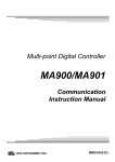
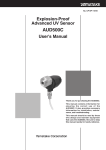
■ Part names
Mounting hole:
4 locations: Use M4 screws.
Indicators, communications connector (CN1)
14
14
13
13
12
12
SHUTTER
(G)
UV SENSOR
(F) 11
11
10
10
9
9
8
8
7
7
6
6
5
5
4
4
3
3
2
2
1
1
Terminals for connection of AUD300C
Advanced UV Sensor:
Connect the AUD300C to these terminals
with M4 screws.
0-5V
K3
K1
K2
Input/output terminals:
Connect the power supply and output devices
with M4 screws.
Chassis ground connection:
The chassis ground connection is also used as a mounting hole.
The paint is scratched off to make a good electrical connection.
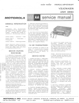
● Terminal pin assignments
2
Terminal No.
Description
14
Advanced UV sensor shutter (white)
13
Advanced UV sensor shutter (white)
12
Advanced UV sensor terminal G (yellow)
11
Advanced UV sensor terminal F (blue)
10
Flame voltage output (–)
9
Flame voltage output (+)
8
K3 relay output
7
K3 relay output
6
Flame output (K1, K2)
5
Common contact output
4
K2 relay (NC flame relay)
3
Start input
2
Power supply (R) high voltage side
1
Power supply (S) ground side
Electrical rating
24Vdc 150mA
(*1)
—
0 to 5Vdc
(*2)
3A 250V (cos φ =1) (*3)
5A 250V (cos φ =1)
—
5A 250V (cos φ =1)
—
100/200Vac 50/60Hz
*1: The shutter has no polarity.
*2: Always use a measuring instrument
having an input impedance of 100 kΩ
or more. Additionally, when
connecting any measuring instrument
to these terminals, use an IV lead wire
with a size of 0.75mm2 or more and a
length of 10m or less.
*3: For the K3 relay, various event
outputs upon the occurrence of an
abnormality can be selected using the
Smart Loader. The factory setting is 3,
meaning that output is ON upon event
occurrence. When the factory setting
for event contents is 2, the K2 relay is
OFF (false discharge).
For details, refer to:
Chapter 5, "Configuration
And Data Reading."
Chapter 1. OVERVIEW
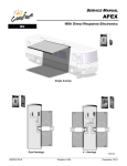
● Indicator details
POWER:
Lights up green when
the power is turned ON.
Address
SHUTTER:
Lights up green when
the shutter is closed.
Loader jack
START CHECK (see below):
Setting 1 overlaps with
settings 2 to 4.
RS-485
communications
connector
14
14
13
13
12
12
FLAME (see below):
Setting 1 overlaps with
settings 2 to 4.
SHUTTER
(G)
UV SENSOR
(F) 11
11
10
10
START CHECK LED operation and display
Setting
Name
Stage of operation Color
Description
1
Synchronized
with K1 relay
Upon start/stop Green
ON/OFF synchronized with K1 relay ON/OFF.
2
Event
occurrence
Upon start/stop
Red
Blinks upon event occurrence (one second
cycling)
3
Inspection
frequency 1
Upon stop
Red
Blinks red for inspection period 1.
Blinks upon stop (with K1 and K2 OFF).
4
Inspection
frequency 2
Upon stop
Red
Blinks red for inspection period 2.
Blinks upon stop (with K1 and K2 OFF).
• The initial setting is 2. (Setting 1 is always active even when setting 2, 3 or 4 is
selected.)
• Operation status:
During operation: The K1 (start check) and K2
(flame) relays are ON.
While stopped: K1 and K2 relays are OFF.
• If notifications of an event occurrence and inspection period are both activated at
the same time, the event has priority.
• If an event (normally a red blink) occurs when the K1 relay is ON (indicated by a
green light), the result is alternating green and orange blinks.
FLAME LED operation and display
Setting
Name
Stage of operation Color
Description
1
Synchronized False flame /
with K2 relay during operation
Green ON/OFF synchronized with K1 relay ON/OFF.
If the flame voltage level has been set, the color
of the light changes.
2
Flame voltage When the K2
Green The color of the light changes according to the
level
relay is energized Orange flame voltage level.
(false flame /
Red
Green: 2.5Vdc or more
during operation)
Orange: 1.5 ≤ voltage < 2.5Vdc
Red: less than 1.5Vdc
The LED goes out upon K2 OFF.
3
Inspection
frequency 3
Upon stop
Red
Blinks red for inspection period 3.
Blinks upon stop (with K1 and K2 OFF).
4
Inspection
frequency 4
Upon stop
Red
Blinks red for inspection period 4.
Blinks upon stop (with K1 and K2 OFF).
The initial setting is 2. (Setting 1 is always active even when setting 2, 3 or 4 is
selected.)
3
Chapter 1. OVERVIEW
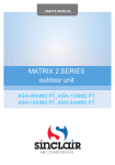
● Switch layout and function
Upper peg
Top
Faceplate sheet
Lower peg
14
14
13
13
12
12
SHUTTER
(G)
UV SENSOR
(F) 11
11
10
10
0-5V
The AUR350C has a station address switch and reset switch for communications.
These switches are located behind the faceplate of the AUR350C display area.
When setting a station address or resetting events, pull the upper portion of the
faceplate toward you in order to remove it from the upper peg, and then slide the
faceplate upward.
Switch layout
S2: Reset selection switch. This
DIP switch is used to select a
reset type.
S3: Reset switch. This switch is used
in combination with the reset
selection switch (S2) to clear the
current frequency value to 0 and also
to reset an event upon event
occurrence. The switch initializes the
contents selected from the table
below. When all S2 DIP switches are
OFF, S3 resets an event.
S1: Rotary switch for station
address. The RS-485
communication address switch
is selectable from 0 to F (15).
This switch is always valid after
power ON. If the station address
is set at 0, communication is not
possible.
Loader jack
RS-485 communications
S2 operation
4
Setting
Description
1
When the reset switch (S3) is turned ON, the current value of
inspection frequency 1 is reset to 0.
2
When the reset switch (S3) is turned ON, the current value of
inspection frequency 2 is reset to 0.
3
When the reset switch (S3) is turned ON, the current value of
inspection frequency 3 is reset to 0.
4
When the reset switch (S3) is turned ON, the current value of
inspection frequency 4 is reset to 0.
Chapter 1. OVERVIEW
■ Model No. key
Series
Basic No. Function Flame
response
Power
supply
Additional
processing
AUR
350C
1
2
3
1
2
00
D0
T0
Description
Advanced UV relay
With communications function
Fixed
Flame response nominal 1.5s
Flame response nominal 3s
100Vac
200Vac
No additional processing
Inspection certificate provided
Tropicalization treatment applied
■ Configuration
● Corresponding flame detector
Name
Advanced UV sensor
Model No.
AUD300C
Name
Flame simulator
Lightning surge absorber
Loader cable
Communications connector
Model No.
123514B
83968019-001
81440793-001
81446848-001
(1 piece)
● Optional parts
5
Chapter 2.
2-1
MOUNTING AND WIRING
Mounting
CAUTION
Do not mount the AUR350C in the following places:
• In the presence of chemicals or corrosive gas, such as ammonia,
sulfur, chlorine, ethylene compound, acid, or others.
• Where it is exposed to water drops or damp atmosphere.
• Where it is exposed to high temperatures.
• Where vibration continues for an extended period of time.
Only authorized personnel who have technical skills with combustion
equipment and flame safeguard control should carry out the pilot turndown
test.
● Mounting position
Mount the AUR350C on a panel.
When mounting the AUR350C vertically, it is possible to gang-mount the unit.
● Mounting procedures
(1) To allow easy removal, heat radiation, wiring, and maintenance work, keep a
work space that is 20mm or more in the vertical direction and 10mm or more
in the horizontal direction as shown in the Figure below.
Vertical mounting
(It is possible to gang-mount the AUR350C.)
20mm
14
14
13
13
12
12
SHUTTER
10mm
(G)
UV SENSOR
(F) 11
11
10
10
9
9
(G)
13
12
12
8
7
7
6
6
5
5
4
3
14
13
10
10
9
9
(G)
13
12
12
UV SENSOR
(F) 11
11
10
10
9
9
8
8
7
7
6
6
5
5
0-5V
8
14
SHUTTER
11
10mm
0-5V
K3
K3
8
8
7
7
6
6
5
5
4
4
4
4
4
3
3
3
3
3
2
2
2
2
2
2
1
1
1
1
1
1
K1
K2
14
13
UV SENSOR
(F) 11
0-5V
K3
14
SHUTTER
K1
K1
K2
K2
20mm
Horizontal mounting
1
2
3
4
5
6
7
8
9
11
10
12
13
14
10mm
20mm
6
1
2
3
4
6
5
K2
K1
7
8
9
10mm
K3
0-5V
10
12
(G)
UV SENSOR
(F) 11
13
SHUTTER
14
20mm
Chapter 2. MOUNTING AND WIRING
(2) Use the drawing below as a guide for making holes in the panel.
Mounting hole
M4 (4 locations)
37±0.5
249±0.5
Mounting hole
M4 (4 locations)
249±0.5
37±0.5
Vertical mounting
Horizontal mounting
Mounting Dimensions
(3) Secure the AUR350C to the mounting holes (four locations) with M4 screws.
Handling Precautions
• Paint is scratched off the lower right mounting hole of the AUR350C
to ensure a good electrical connection. This hole is used as the
chassis ground connection. Use a toothed lock washer for a good
electrical connection.
• When mounting the AUR350C horizontally, it is not possible to use
gang-mounting.
7
Chapter 2. MOUNTING AND WIRING
2-2
Wiring
WARNING
Before wiring the AUR350C, be sure to turn the power OFF. Failure to do so
might cause electric shock.
CAUTION
Carefully perform the mounting and/or wiring work while referring to this
user's manual, as well as the instruction manuals published by the equipment
manufacturers.
Check the insulation of each wire. Faulty insulation may cause a ground fault
or an electric shock.
Carry out the wiring work in conformity with the specified standards.
Always connect the power supply last. Otherwise, touching a terminal
accidentally may cause electric shock or damage.
The load connected to each terminal must not exceed the rating shown in the
specifications.
Always supply electric power with the voltage and frequency stated on the
model label of the AUR350C.
If timers and auxiliary relays are needed to for additional functions, always
select those with high reliability and be sure to design the circuit correctly.
The AUR350C must be grounded with a resistance of less than 100Ω, as
described in technical standards for electrical equipment. The ground wire
must be connected to the burner chassis.
The power cable and high-voltage cable of the ignition transformer must be
separated from the power cable of the AUD300C.
The high-voltage cable of the ignition transformer must be separate and kept
10 cm or more away from the AUR350C.
Connect the high-voltage cable of the ignition transformer securely so that
there is no faulty contact. A faulty connection will produce high-frequency
radio waves, causing radio interference or malfunction. Additionally, mount
the ignition transformer directly on the burner main unit or on a metallic part
electrically connected to the burner main unit.
After the wiring has been done, always check that it is correct. Incorrect
wiring may cause damage or malfunction.
8
Chapter 2. MOUNTING AND WIRING
■ Wiring diagram
● Monitoring of burner flame
13
12(G)
Blue
11(F)
DA
FLAME LED
DC0 to 5V
Microprocessor
START
CHECK LED
Flame voltage
output circuit
Measuring
instrument
Microprocessor
Flame voltage
output circuit
Measuring
instrument
10
9
10
9
K3-1
K3 relay output
DB
11(F)
FLAME LED
0 to 5Vdc
SG
LOADER
Yellow
K2
RS-485 communications
White
SHUTTER LED
K2 driving circuit
Blue
DA
14
Flame amplifying circuit
12(G)
DB
LOADER
Flame amplifying circuit
Yellow
Shutter driving
circuit
13
K2
White
SG
Advanced UV sensor
White
SHUTTER LED
RS-485 communications
14
K2 driving circuit
Advanced UV sensor
Shutter driving
circuit
White
● Manual ignition (intermittent pilot)
START
CHECK LED
K3-1
8
K3 relay output
7
Start switch
8
7
K1-3
K1-3
Main valve
Flame output
6
6
K2-2
K2-2
Common contact output
5
5
K2 NC
Ignition transformer
Start check circuit
4
K1-2
K1
Start check circuit
4
K1-2
K1
Start contact
Pilot valve
3
K2-1
3
K1-1
Limit
POWER LED
2(R)
1(S)
AC
K2-1
K1-1
POWER LED
2(R)
Power supply
circuit
Power supply
circuit
AC
Stop switch
1(S)
Handling Precautions
• If the high voltage side (H) of the power supply is distinguished from the
grounded side (G), connect the high voltage side (H) to terminal 2 (R)
and the grounded side (G) to terminal 1 (S).
• For wiring to the power source, use a 0.75mm2 wire (0.18mm dia., 30
cores) in keeping with JIS C3306.
• Connect an FS4.8 series flat connection terminal (equivalent to a #187
series receptacle made by AMP) to the end of the cable, and then do the
wiring, keeping the wire as short as possible.
• Playback data may be erased if equipment operation stops for more
than 4 hours.
9
Chapter 2. MOUNTING AND WIRING
● Connecting with surge absorber
When using the optional surge absorber (model 83968019-001) as a protective
measure against lightning, connect it as shown below.
AUR350C
AUR350C
Voltage side (H)
Power supply
Grounded side (G)
Voltage side (H)
2 (R)
Power supply
2 (R)
1 (S)
1 (S)
Grounded side (G)
Surge absorber
(83968019-001)
Flat terminal, FS4.8-series terminal side
Mounting bracket side (grounded side)
Handling Precautions
• Connect the flat connector FS4.8 series (AMP's #187 series receptacle
or equivalent) to one end of the electric cable and make the wiring as
short as possible.
• The grounded side of the metallic bracket for mounting of the surge
absorber is crimped internally so it makes good electrical contact.
Mount this bracket on a metallic part such as the burner chassis to
connect the ground wire.
■ Connection to the AUD300C
Wire the AUD300C as shown below.
AUD300C
Advanced UV Sensor
AUR350C
Advanced UV Relay
White
White
Yellow
Blue
14
13
12
(G)
11
(F)
Handling Precautions
• The signal wires of the AUD300C (blue and yellow) have specific
polarities. Connect the blue wire to terminal 11 (F) of the AUR350C and
the yellow wire to terminal 12 (G).
Reversing the signal wires may cause the tube unit to break or
malfunction.
•
10
To extend the wiring, use 2mm2 600V-vinyl insulated IV cable with a
length of 200m or less.
Chapter 2. MOUNTING AND WIRING
■ Wiring to solenoid valve
WARNING
Do not connect the solenoid valve to the high voltage side. If a ground fault
occurs, the ground fault current may flow into the solenoid valve. The
AUR350C, will not be able to prerent the valve from opening and fuel from
flowing out.
● Correct connection
High voltage side (H)
N
L
Burner
AUR350C
Grounded side (G)
(Ground fault)
Valve (closed)
Combustion equipment
Power supply
Fuel
When the valve wiring is connected correctly as shown in the figure above, current
does not flow through the solenoid valve even if a ground fault occurs due to
faulty insulation on the high voltage side. Therefore, the valve does not open and
fuel does not flow out.
● Incorrect connection
(Ground fault)
High voltage side (H)
N
L
Valve (open)
Burner
AUR350C
Grounded side (G)
Combustion equipment
Power supply
Fuel
If the valve wiring is connected to the high voltage side, current flows through the
solenoid valve if a ground fault occurs, as shown in the figure above. Therefore,
the valve opens in spite of the AUD350C and fuel flows out.
■ Cautions for continuous measurement of flame voltage
• Connect a measuring instrument to the AUR350C having an input impedance
of 100kΩ or more and connect a pen recorder having an input impedance of
1MΩ or more.
• Always use an IV cable with a size of 0.75 mm2 or more for signal lines. The
wiring length must be 10m or less.
11
Chapter 2. MOUNTING AND WIRING
2-3
Communications Connection
■ Communications with the Smart Loader
Address
Loader jack
PC with Smart Loader package
14
14
13
13
12
12
UV SENSOR
(F) 11
11
SHUTTER
(G)
Handling Precautions
• Transmission distance is 10m or less.
• Connect using a modular jack.
■ Connection to display devices
1:1
display device
14
14
13
13
12
12
14
14
13
13
12
12
UV SENSOR
(F) 11
11
UV SENSOR
(F) 11
10
10
10
SHUTTER
(G)
display device
K3
9
9
8
8
7
7
6
6
12
11
UV SENSOR
(F) 11
10
10
5
5
4
(G)
14
14
13
13
12
12
11
UV SENSOR
(F) 11
11
UV SENSOR
(F) 11
11
10
10
10
10
10
9
9
8
8
7
7
6
6
5
5
SHUTTER
0-5V
9
8
8
7
7
6
6
9
8
8
7
7
6
6
5
5
5
5
4
4
4
4
3
3
3
3
2
1
2
2
1
1
K2
AUR350C connection with display device
EST display device
5-wire system
3-wire system
SDA
SDB
RDA
RDB
SG
DA
DB
SG
(G)
14
14
13
13
SHUTTER
0-5V
9
(G)
12
12
0-5V
9
9
8
8
7
7
6
6
5
5
4
4
4
4
4
3
3
3
3
3
3
2
2
2
2
2
2
2
1
1
1
1
1
1
1
K1
AUR350C
12
13
12
9
K3
1:1
DA
DB
SG
14
13
SHUTTER
0-5V
K1
K2
14
SHUTTER
(G)
0-5V
DA
DB
SG
A maximum of 15 AUR350C
units can be connected.
1:n (n≤15)
K3
K1
K2
K3
K1
K2
K3
K1
K2
Note
• For the 1:n connection examples, refer to the
instructions for 3-wire and 5-wire system connections (page 14).
Chapter 2. MOUNTING AND WIRING
■ RS-485 communications
Signal level
RS-485-compliant
Transmission line
connection
Multipoint
Synchronous method
Start-stop synchronization
Transmission control
Polling/selecting method
Maximum length of
extension cable
Max. 500m
Transmission speed
error
Max. 0.16%
Transmission speed
19200bps
Data length
8 bits
Stop bit length
1 bit
Parity
Even
Error detection
Vertical redundancy check
● Communications connection
Using the RS-485 communication ports (DA, DB, SG), up to 15 units can be
connected.
(3-wire system)
Master station
AUR350C (CN1 pins 1-3)
DA+
→
DA
DB→
DB
SG
→
SG
● Communications settings
Station address is set by rotary switch (S1).
The items shown in the table below can be set with the Smart Loader. (Settings
take effect after power is restarted.)
Item
Description
Initial value
Data format
Data length 8 bits, even parity, 1 stop bit 8 bits, even parity, 1 stop bit
or 8 bits, no parity, 2 stop bits
Transmission
speed
19200/9600/4800/2400bps
Minimum
1/10/100/200ms
response time
19200bps
10ms
13
Chapter 2. MOUNTING AND WIRING
■ Connection with a 3-wire system
AUR350C
DA
DB
SG
EST series
smart terminal
DA
DB
SG
FG
AUR350C
DA
DB
SG
AUR350C
DA
DB
SG
■ Connection with a 5-wire system
AUR300C
DA
DB
SG
EST series
smart terminal
SDA
SDB
*
*
RDA
RDB
SG
FG
AUR350C
DA
DB
SG
AUR350C
DA
DB
SG
Handling Precautions
• Do not connect terminating resistors on communications circuits.
• Ground shielded wire to one point on one side of the cable.
• Wire the connections marked with an asterisk (*) externally, when five
RS-485 terminals are used.
• Use a twisted shielded pair cable for RS-485 communications.
• Be sure to connect the SG terminals together. Failure to do so might
cause unstable communications.
14
Chapter 3.
OPERATION
POWER LED
K1-1
AC
Switch and
controller
Power ON
Limit ON
AUR350C operation
• Power is applied to terminals 1 (S) and
and 2 (R). (Power is applied to the
AUR350C relay.)
POWER
LED
●
1(S)
K2-1
3
Pilot valve
Stop switch
4
Ignition transformer
Advanced UV sensor
5
K2-2
6
7
Start switch
Main valve
Measuring
instrument
K3 relay output
8
9
10
0 to 5Vdc
11(F)
12(G)
Blue
Yellow
13
White
White
14
K3-1
K1-3
Flame voltage
output circuit
Flame amplifying circuit
K1-2
K2 driving circuit
Shutter driving
circuit
Power supply
circuit
Limit
K2
Microprocessor
K1
LOADER
2(R)
FLAME LED
AUR350C
START
CHECK LED
SHUTTER LED
RS-485
communications
START
CHECK LED
DA
DB
SG
Manual ignition method (intermittent pilot)
K1: Start check
K2: Flame detection
K3: Combustion lamp
SHUTTER
START
LED
CHECK LED
FLAME
LED
• When power is applied to terminal 3,
the K1 relay is turned ON through the
K2-1 flame relay contact (if closed: false
flame check)
• When the pilot flame is detected, the
flame relay (K2) is turned ON. The
output of the pilot valve continues while
the K1 relay is ON and contacts K1-1
and K1-2 are closed.
• When K2-2 and K1-3 close, the main
valve enters the stand-by mode.
• When K3-1 closes, the combustion lamp
lights up.
●
●
●
●
●
●
●
●
●
●
●
Start switch OFF
• When power is applied from terminal 3
to terminals 5 and 6, the main valve is
operated.
●
●
●
Stop operation:
stop sw. OFF
• All relays are turned OFF.
Flame shutoff
during operation
• All relays are turned OFF.
Start switch ON
●: Lit,
: Off,
●
: Flashing
15
Chapter 3. OPERATION
Transition from normal operation to flame shutoff operation
Power switch ON
Start switch ON
Flame detection
Start switch OFF
Flame failure
Flame response
Power switch
Start switch
Ignition transformer
Pilot valve
Main valve
K3 relay output
POWER LED
SHUTTER LED
START CHECK LED (K1)
FLAME LED (K2)
FLAME
False flame exists before ignition
Power switch ON
False flame
Start switch
ON
Start switch OFF
Power switch
Start switch
Ignition transformer
Pilot valve
Main valve
K3 relay output
POWER LED
SHUTTER LED
START CHECK LED (K1)
FLAME LED (K2)
FLAME
Flame signal exists while the shutter is closing
Power switch ON
False flame
Start switch
ON
Start switch OFF
Power switch
Start switch
Ignition transformer
Pilot valve
Main valve
K3 relay output*
POWER LED
SHUTTER LED
START CHECK LED (K1)
FLAME LED (K2)
FLAME
*Since the intial setting of the K3 relay output is 3 (upon event
occurrence), K3 relay output is ON.
16
Chapter 4.
TRIAL-RUN ADJUSTMENT
WARNING
The pilot and main burner ignition time must not exceed the ignition time
specified by the burner or equipment manufacturer. If they do, fuel may
accumulate in the combustion chamber to form an explosive mixture, causing
a serious explosion hazard.
Never touch any terminal of the AUR350C during trial-run adjustment.
Doing so may cause an electric shock.
Before removing or mounting the AUR350C, be sure to turn the power OFF.
Failure to do so may cause an electric shock.
Before starting the pilot turndown test or ignition spark response test, always
check that all manual fuel valves are closed.
Do not begin actual operation until the trial-run adjustment tests and tests
specified by the equipment manufacturer are completed.
Never touch terminal 11 (F) immediately after the power has been turned
OFF. Terminal 11 (F) is electrically alive for 1 minute after the power to the
AUR350C has been turned OFF. Touching it may cause an electric shock.
■ Outline of adjustment
The following shows the test adjustment items described in this chapter:
• Measurement of flame voltage
• Pilot turndown test
• Ignition spark response test
• Safety shutoff test
Handling Precautions
• After the above items have been adjusted, check again that each
adjustment is satisfactory. It is absolutely necessary for all
adjustments to be correct before the final positioning of the flame
detector.
● Tools and parts needed
• Multimeter:
Input impedance: 100kΩ or more
AC range: 0 to 300V
DC range: 0 to 10V
• Jumper cables with clips (2)
17
Chapter 4. TRIAL-RUN ADJUSTMENT
■ Preliminary inspection
(1) Inspect all wiring parts.
(2) Check that the AUR350C is mounted in a place where the ambient
temperature is within its allowable range.
(3) Check that the AUD300C is mounted correctly. In particular, be sure the blue
lead wire (to terminal 11) and yellow lead wire (to terminal 12) of the
AUD300C are connected correctly. For details, refer to the user's manual for
the AUD300C, No. CP-SP-1141E.
(4) Check that the valves and cocks of each fuel system are closed and that the
inside of the fuel chamber is vented sufficiently.
(5) After items 1 to 4 above have been checked, supply the power and start the
trial-run adjustment.
■ Measurement of flame voltage (flame signal)
Start the equipment and measure the voltage under several conditions, such as
start-up operation and normal operation.
(1) Set the multimeter to the 0 to 10Vdc range.
(2) Connect the + (positive) probe of the multimeter to terminal 9 and the (negative) probe to terminal 10.
(3) Check that the voltage is stable at a recommended flame voltage of 2.0 to
4.0V for the 1.5s flame response time type and 1.5 to 4.0V for the 3s flame
response time type.
(4) If the flame voltage fluctuates widely, check the AUD300C's mounting
position, wiring, and the line.
Handling Precautions
• Even during normal operation, the flame voltage is synchronized with the
shutter operation of the AUD300C and fluctuates in a range of 0.1 to
0.3V.
18
Chapter 4. TRIAL-RUN ADJUSTMENT
■ Pilot turndown test
This test is intended to check that the flame is reliably transferred to the main
burner when the AUD300C detects a pilot flame if the gas pressure and air
pressure are changed to their worst conditions.
WARNING
If the AUD300C detects a pilot flame that is too small to ignite the main
burner, the AUR350C will not recognize a flame failure in the main burner. In
this case fuel would flow out continuously, causing a serious explosion
hazard. To prevent such an occurrence, always perform the pilot turndown
test carefully.
When performing the pilot turndown test repeatedly, stop the equipment
completely every time the pilot turndown test is completed in order to vent the
unburnt gas or oil that has accumulated in the combustion chamber or flue
completely. If unburnt gas or oil is not purged completely, an explosion may
occur.
After the pilot turndown test has been completed, turn OFF the power switch
to shutdown the power. Restore all test jumpers and limit/regulator settings
to their previous states. If operation begins without the above steps, damage
to the equipment, gas leak or explosion may result.
CAUTION
Only authorized personnel who have technical skills with combustion
equipment and flame safeguard control should carry out the pilot turndown
test.
Handling Precautions
• If a fuel pressure limit switch is used, and its contacts are open, turn it
ON with a jumper cable during this test.
To carry out the pilot turndown test, follow the steps below.
● Preparations before test
(1) Turn OFF the power switch.
(2) Close the manual valves to stop the gas supply to the pilot burner and main
burner.
(3) Open the manual valve for the pilot burner.
● Check a gas pressure level, at which the AUD300C cannot detect the pilot flame.
(4) Turn ON the power switch and press and hold the start switch.
>> The ignition operation begins, the pilot valve opens, and the ignition
transformer is activated. The flame relay turns ON and the combustion lamp
lights up.
19
Chapter 4. TRIAL-RUN ADJUSTMENT
(5) Close the manual valve for the pilot burner slowly.
The pilot flame gradually becomes smaller. Gradually close the valve until
the AUD300C cannot detect the flame.
(6) Record the gas pressure immediately before the flame relay turns OFF and the
combustion lamp goes off. Release the start switch.
● Check that the main burner can be ignited with the minimum pilot flame.
(7) Press and hold the start switch again.
(8) Open the manual valve for the pilot slowly to adjust the pressure to a level
immediately before the combustion lamp goes off. Check that the flame relay
is turned ON and that the combustion lamp is lit up.
(9) Release the start switch.
(10) Check that the main burner is ignited smoothly within 1 second after the
manual valve for the main burner has opened.
(11) Change the gas pressure level between the minimum and maximum levels and
ignite the main burner five or six times. Be sure that the main burner ignites
smoothly every time.
● If the main burner does not ignite with the minimum pilot flame.
(12) Adjust the mounting position of the AUD300C and the amount of incoming
light so that the AUD300C cannot detect a pilot flame that cannnot ignite the
main burner.
There are two kinds of adjustment procedures.
• Move the monitoring area of the sighting pipe slightly away from the pilot
flame.
• Narrow the sighting pipe to decrease the incoming light amount from the
pilot flame.
(13) Open the manual valve for the pilot burner slowly to make the pilot flame
larger than the previous flame.
● After adjustment, check again that the main burner can be ignited with the minimum pilot
flame.
(14) Perform steps 7-11 ("Check that the main burner can be ignited with the
minimum pilot flame") again.
● Measures to be taken after completion of the test
(15) After the test has been completed, return the manual valve of the main burner
to its fully open position.
(16) Check that the flame voltage is correct.
(17) If any limit switch has jumper cables attached, disconnect them to return the
limit switch to its previous state.
20
Chapter 4. TRIAL-RUN ADJUSTMENT
■ Ignition spark response test
WARNING
Be sure the AUD300C does not detect ultraviolet rays other than those of the
burner flame. If the AUD300C responds to other ultraviolet rays, flame failure
in the burner will go unnoticed, allowing fuel to flow continuously, causing a
serious explosion hazard.
(1) Close the manual fuel valves of the pilot and main burners.
(2) Begin operation and measure the flame voltage in the pilot ignition sequence
to check whether or not the flame voltage is influenced.
(3) If the FLAME LED is lit, make adjustments using the following procedures
while referring to the instruction manual for the equipment:
• Move the AUD300C or ignition spark rod so that there is no influence.
• Put a shielding plate in the optical path of the AUD300C so that the effect
of the spark is a flame signal of 0.4Vdc or less.
Handling Precautions
• Be sure the AUR350C does not detect ultraviolet rays other that those of
the burner flame.
• The following shows various ultraviolet ray sources other than the burner
flame that may activate the AUD300C:
Ultraviolet ray source
Gamma ray and
X ray source
Red-hot furnace wall (within 50 cm of furnace wall)
Ignition transformer and welding arc
Gas laser
Sunlamp
Disinfecting lamp, ultraviolet lamp, fluorescent lamp
Strong flashlight (toward UV sensor)
Regression analyzer
Electron microscope
X-ray camera
High voltage vacuum switch
High voltage capacitor
Radioisotope
Other sources producing ultraviolet rays, gamma rays,
and X-rays
21
Chapter 4. TRIAL-RUN ADJUSTMENT
■ Safety shut-off test
After all operational adjustments have been completed, carry out the safety shutoff
test.
● Pilot ignition failure (ignition failure)
(1) Close the pilot and main manual fuel valves.
(2) Press the start switch.
>> Operation begins.
(3) Normally, at pilot burner ignition, the pilot valve opens. Check that the
FLAME LED does not light up and that the main valve does not open if the
flame fails.
● Flame failure during normal combustion
(1) Open the pilot and main manual fuel valves.
(2) Press the start switch to begin operation.
(3) When the sequence has progressed correctly and normal combustion has
begun (main valve has opened), close the pilot and main manual fuel valves to
put out the burner flame. Then, check that flame failure is detected and that
safety shutoff is correctly activated.
22
Chapter 5.
CONFIGURATION AND DATA READING
■ K3 relay output (set by the Smart Loader)
The K3 relay’s mode of operation can be selected, as shown in the table below.
● Selection of K3 relay operation
Setting
Name
1
2
3
Synchronized with K1
Synchronized with K2
Upon event occurrence
4
Flame voltage upper limit
5
Flame voltage lower limit
6
Inspection frequency 1
7
Inspection frequency 2
8
Inspection frequency 3
9
Inspection frequency 4
10
Communications command
K3 relay operation
Operates in the same way as the K1 relay.
Operates in the same way as the K2 relay.
ON when an event occurs. (Refer to; Event selection and
resetting.)
ON when flame voltage exceeds the value set as the upper
limit. The flame voltage upper limit is set with the Smart Loader.
ON when flame voltage drops below the value set as the
flame voltage lower limit. The flame voltage lower limit is set
with the Smart Loader.
ON when inspection frequency 1 is set. (Refer to; Inspection
frequency setting and resetting.)
ON when inspection frequency 2 is set. (Refer to; Inspection
frequency setting and resetting.)
ON when inspection frequency 3 is set. (Refer to; Inspection
frequency setting and resetting.)
ON when inspection frequency 4 is set. (Refer to; Inspection
frequency setting and resetting.)
ON when writing to communication address 3900W through
RS-485.
Initial setting: 3. (Multiple selections are possible.)
Handling Precautions
• If there are multiple event selections, K3 is energized when one of the
operating conditions is satisfied, and de-energized when none of the
operating conditions are satisfied.
Note
• Selection 3: Upon event occurrence
This provides information about the operation of the flame detector or the status of burner flame detection. A history of the past 8
occurrences of an event can be stored in nonvolatile memory.
• Selections 4 - 5: Flame voltage upper/lower limit
The flame voltage upper limit and lower limit can be used as a
sort of meter relay. The upper and lower limits can be used to
regularly check the flame voltage. The flame voltage may vary
depending on various factors, such as air-fuel ratio, fuel pressure,
deterioration of the burner, and/or deterioration of the flame sensor. Because the frequency of burner operation can be checked
by flame voltage limit data, the data can be utilized to determine
how often maintenance is needed.
• Selections 6 - 9: Inspection frequencies 1 to 4
The frequency of a notification that an inspection is due depends
on the operation time or operation cycles of the burner. These
selections are used as a substitute for a counter and cumulative
timer. Additionally, it is possible to call up actual values through
RS-485 communications or to learn that an inspection is due
from the LED display.
23
Chapter 5. CONFIGURATION AND DATA READING
● Sub-settings related to the K3 relay operation selection (set by the Smart Loader)
Sub-setting
ON delay time
OFF delay time
Flame voltage
upper limit value
Flame voltage
lower limit value
Description
Initial
value
The delay before K3
relay ON (0.1 to 5.0
seconds)
The delay before K3
relay OFF (0.1 to 5.0
seconds)
The flame voltage upper
limit (0 to 5.0Vdc)
The flame voltage lower
limit (0 to 5.0Vdc)
1.0s
Remarks
1.0s
4.0V Recommended flame voltage is
1.5 to 4.0Vdc.
1.5V
Handling Precautions
• Use the K3 relay output for monitoring or prediction. Do not use the K3
relay output as a burner shutoff signal, because if the K3 relay output is
used for burner shutoff, burner combustion may be stopped even during
normal operation.
• Use the data read through communications for monitoring only. Do not
use it for purposes of control.
24
Chapter 5. CONFIGURATION AND DATA READING
■ LED display
The function of the LED indicators (START CHECK LED / FLAME LED) can be
selected, as shown in the table below. Multiple selections are possible, in which
case a logical OR operation of the selected items is performed.
● START CHECK LED operation and display
Setting
Name
1
Synchronized
with K1 relay
Upon event
occurrence
Inspection
frequency 1
Inspection
frequency 2
2
3
4
Stage of operation Color
Description
Upon start/stop
Green
ON/OFF synchronized with K1 relay ON/OFF
Upon start/stop
Red
Upon stop
Red
Upon stop
Red
Blinks upon event occurrence (one second
cycling)
Blinks red for inspection period 1. Blinks upon
stop (with K1 and K2 OFF).
Blinks red for inspection period 2. Blinks upon
stop (with K1 and K2 OFF).
• The initial setting is 2. (Setting 1 is always active even when setting 2, 3 or 4 is
selected.)
• Operation status:
During operation: the K1 (start check) and K2
(flame) relays are ON.
While stopped: the K1 and K2 relays are OFF.
• If notifications of an event occurrence and inspection period are both activated at
the same time, the event has priority.
• If an event (normally a red blink) occurs when the K1 relay is ON (indicated by a
green light), the result is alternating green and orange blinks.
● FLAME LED operation and display
Setting
1
2
3
4
Name
Stage of operation Color
Description
Synchronized False flame /
with K2 relay during operation
Green ON/OFF synchronized with K2 relay ON/OFF.
If the flame voltage level has been set, the color
of the light changes.
Flame voltage When the K2
Green The color of the light changes according to the
level
relay is energized Orange flame voltage level.
(false flame /
Red
Green: 2.5Vdc or more
during operation)
Orange: 1.5 ≤ voltage < 2.5Vdc
Red: less than 1.5Vdc
The LED goes out upon K2 OFF.
Inspection
Upon stop
Red Blinks red for inspection period 3. Blinks upon
frequency 3
stop (with K1 and K2 OFF).
Inspection
Upon stop
Red Blinks red for inspection period 4. Blinks upon
frequency 4
stop (with K1 and K2 OFF).
• The initial setting is 2. (Setting 1 is always active even when setting 2, 3 or 4 is
selected.)
25
Chapter 5. CONFIGURATION AND DATA READING
■ Inspection frequency setting and resetting (using the Smart Loader)
The AUR350C accumulates and stores data about operation time (when current is
continuously applied), combustion time, and/or number of combustion ON times,
depending upon the user’s selections. The frequency of each inspection can be set
on the basis of this data.
● Inspection frequency settings
Item
Operation
Selection
Inspection
frequency 1
Inspection
frequency 2
Inspection
frequency 3
Inspection
frequency 4
0: None
1: Operation time
2: Combustion time
3: No. of combustion starts
0: None
1: Operation time
2: Combustion time
3: No. of combustion starts
0: None
1: Operation time
2: Combustion time
3: No. of combustion starts
0: None
1: Operation time
2: Combustion time
3: No. of combustion starts
Intial setting
0: None
0: None
0: None
0: None
Inspection interval settings
Range
Intial setting
––
0–99,999 hrs.
0–99,999 hrs.
0–99,999 times
––
0–99,999 hrs.
0–99,999 hrs.
0–99,999 times
––
0–99,999 hrs.
0–99,999 hrs.
0–99,999 times
––
0–99,999 hrs.
0–99,999 hrs.
0–99,999 times
––
25,000 hrs.
20,000 hrs.
10,000 times
––
25,000 hrs.
20,000 hrs.
10,000 times
––
25,000 hrs.
20,000 hrs.
10,000 times
––
25,000 hrs.
20,000 hrs.
10,000 times
● Inspection frequency resettings
To reset an inspection frequency to 0, do as follows:
By switch:
Use the S2 reset selection switch and the S3 reset switch on the
display unit of the AUR350C (see page 4).
Communication: Write “0” to the appropriate RS-485 communication address,
1121 to 1128W (see the address map on page 47). Alternatively,
use the Smart Loader (refer to manual CP-UM-5319E).
Note
• Whether or not the operation time, combustion time, and the number of combustion starts exceeds those stated in inspection frequencies 1 to 4, the user can check
on inspection notification occurrence status using RS-485 communications
address 1120W.
26
Chapter 5. CONFIGURATION AND DATA READING
■ Event contents selection and resetting (using the Smart Loader)
An event provides information about the operation of the flame detector or the
status of burner flame detection. When an event occurs, it is indicated by K3 relay
output or by LED. Additionally, a history of the past 8 occurrences of an event can
be stored in nonvolatile memory. (Unselected events are not stored.)
● Event contents selection
Setting
Name
Reset method
Description
K2 (the flame relay) is ON before start, and K1 (the
start check relay) is not activated. The cause might
be a false flame or contact welding of K2.
The shutter is closed when K2 is OFF (flameout).
The cause might be a shutter failure, tube unit failure
or the failure of the flame detection circuit of the
AUR350C. (A flame is detected even though the
shutter is closed: the tube unit or flame detection
circuit detects a flame in the shutter-closed state.)
This is an alarm output for maintenance when the
shutter-closed time becomes longer during operation
(with K1 and K2 relays both ON). If the AUR350C is
not working properly, the shutter closing time
becomes longer.
Probable causes:
• The UV tube has deteriorated and has begun to
self-discharge.
• Shutter malfunction
• Shutter cannot close off the light because of diffused
reflection due to overly strong ultraviolet rays.
The shutter is normally closed for approximately 0.5 to
0.7 seconds (at a 3.5Vdc flame voltage).
The F and G wires of the AUD are short-circuited.
1
False flame
Automatic or by
resupplying power
2
K2 relay OFF
(while shutter
is closed),
false
discharge
Switch,
communications,
restart, resupplying
power
3
Shutter-closed
time
increases
during
operation
Switch,
communications,
restart, resupplying
power
4
F-G short
Automatic, power
circuit
resupply
Flame voltage Automatic, switch,
decrease
communications,
restart, resupplying
power
5
6
K2 relay OFF Automatic, switch,
(while shutter communications,
is open)
restart, resupplying
power
The flame voltage decreases during operation (with
K1 and K2 both ON). This is an alarm output for
maintenance.
The check starts 15 seconds after K2 is energized
and continues until 4 seconds before K2 is deenergized, and then the flame voltages are compared.
This is to catch a flame voltage drop caused by dirt or
deterioration of the tube unit or a change in the burner
combustion state during a long period of operation.
K2 is de-energized during operation, and no flame is
detected even though the shutter is open.
The initial setting is 2. (Multiple selections are possible.)
Handling Precautions
• Setting 6, K2 relay OFF (while shutter is open)
The AUR350C cannot tell whether a decrease of flame voltage is
because the flame has gone out or because the burner has been shut
down. Since history data is overwritten if many shutdowns occur, care
must be taken in use. If few shutdowns occur, or if the power is turned
OFF to stop combustion, this event setting can be used for flame failure.
27
Chapter 5. CONFIGURATION AND DATA READING
● Sub-settings related to event contents selection (set by the Smart Loader)
Sub-settings
Range
Intial value
Description
Shutter-closed time
0.1 to 5.0s
3.0s
Shutter-closed time threshold value (setting 3)
Time between
decrease and
recovery of flame
voltage
0.1 to 5.0s
1.0s
The time to continue below the value set for
flame voltage decrease (setting 5).
Flame voltage
decrease set value
0 to 5.0V
1.5V
Setting 5
● Resetting events
Automatic:
When the equipment returns to normal status, events are automatically cancelled and reset. The flame voltage decrease event
is cancelled when the current flame voltage exceeds the set
value + 0.1V for longer than the value set as the time between
decrease and recovery of flame voltage.
Restart:
Events can be reset when K1 is energized from the stop state.
Resupplying power: Events can be reset after power is resupplied.
Switch:
Events can be reset by pressing the S3 switch after turning OFF
all DIP switches (4 points) of switch S2 on the display area of
the AUR350C.
Communications: Events can be reset by writing to RS-485 communications
address 3805W (see the address map on page 51). It can also be
reset by the Smart Loader (refer to manual CP-UM-5319E).
28
Chapter 5. CONFIGURATION AND DATA READING
■ Playback display data
The built-in RAM memory of the AUR350C accumulates a total of 10 seconds of
data at 0.1 second intervals concerning shutter operation, flame voltage and
number of discharges. The data can be output using the Smart Loader or through
RS-485 communications. A memory buffer is allocated for the 10 seconds of data
(hereafter referred to as playback data) and is continually updated. When updating
is stopped by one of the triggers described below, the data about flame voltage,
shutter operating cycle, etc., that accumulated in the memory for 10 seconds
before the event trigger occurred can be checked. The event trigger, cumulative
operation time and number of combustion starts are linked to the playback data.
Selections can be set using the Smart Loader. Multiple event triggers can also be set.
● Event trigger selection
Setting
Name of trigger
1
2
3
4
5
K2 OFF
K3 ON
K3 OFF
Event occurrence
Flame voltage increase
6
Flame voltage decrease
7
Shutter-closed time
exceeded
8
Shutter-open time
exceeded
9
Communications command
Description
When K2 is de-energized, the trigger is activated.
When K3 goes from OFF to ON, the trigger is activated.
When K3 goes from ON to OFF, the trigger is activated.
When an event occurs, the trigger is activated.
When the flame voltage increases above the upper limit value
during operation, the trigger is activated.
When the flame voltage decreases below the lower limit value
during operation, the trigger is activated. (The trigger is not
activated when K2 is OFF.)
When the shutter-closed time exceeds the set value during
operation, the trigger is activated. (The trigger is not activated
when K2 is OFF.)
When the shutter-open time exceeds the set value during
operation, the trigger is activated. (The trigger is not activated
when K2 is OFF.)
When "35AC" is written to address 3901W through RS-485
communications, the trigger is activated.
The initial setting is 2.
Handling Precautions
• Backup time for playback data is 4 hours or more at room temperature
(the average value is 12 hours).
● Sub-settings related to event trigger setting (set by the Smart Loader)
Sub-settings
Operation delay time
Range
0.1 to 5.0s
Updating of playback
Flame voltage
upper limit value
Flame voltage
lower limit value
Shutter-closed time
value
0 to 5.0V
Shutter-open time
value
0.1 to 5.0s
0 to 5.0V
0.1 to 5.0s
Intial value
Description
1.0s
The length of time that the trigger conditions for
flame voltage increase or decrease must
continue before the trigger is activated.
1 (update) Four areas are allocated for playback data. This
setting controls whether updating continues after
the trigger has been activated 4 times.
4.0V
Upper limit for flame voltage. When the flame
voltage exceeds this value, the trigger is activated.
1.5V
Flame voltage lower limit. When flame voltage
falls below this value, the trigger is activated.
3.0s
Upper limit for shutter-closed time. When the
shutter-closed time exceeds this value, the
trigger is activated.
3.0s
Upper limit for shutter-open time. When the
shutter-open time exceeds this value, the trigger
is activated.
29
Chapter 5. CONFIGURATION AND DATA READING
■ Maintenance data
This includes event history (8 items), number of occurrences of each event,
cumulative operating time, cumulative combustion time, cumulative number of
combustion starts, operating time, combustion time, the number of combustion
starts, AUR memo, etc. Event data can be read out by the Smart Loader or RS-485
communications.
Data item
Event history
Occurrences of each
event (*1)
Cumulative operation
time (*2)
Cumulative combustion
time (*2)
Cumulative occurrences
of combustion
Operation time (*2)
Combustion time (*2)
Occurrences of
combustion
AUR memo
Flame voltage
Shutter operation cycle
Relay operation
Operation status
Description
Eight ring buffers are available. They are linked to the operation time
at event occurrence or the number of combustion starts.
How many times the event occurred.
Range = 0 to 255 times. (*1)
The length of time that power was supplied.
Range = 0 to 99,999 hrs.
The length of time that both K1 and K2 relays were ON.
Range = 0 to 99,999 hrs.
Cumulative number of combustion starts.
Range = 0 to 99,999 times
The length of time that power was supplied.
Range = 0 to 99,999 hrs. (for measurement purposes)
The length of time that both K1 and K2 relays were ON.
Range = 0 to 99,999 hrs. (for measurement purposes)
Number of combustion starts.
Range = 0 to 99,999 times (for measurement purposes)
A comment up to 60 words (upper case) can be written into the AUR
memo by using the Smart Loader.
Average value per second, average value per minute, maximum
value, minimum value (during K2 ON).
Average value per minute, maximum value, minimum value (during
K2 ON).
Feedback from K1, K2 and K3 relays.
Event occurrence status, operation status
*1 The occurrences are counted regardless of whether the event was
selected.
*2 The unit for time data is seconds. Cumulative operation time and
operation time are the same.
30
Chapter 6.
6 - 1
COMMUNICATIONS FUNCTIONS
Outline of Communications
Because the AUR350C is equipped with RS-485 communications capabilities, communications with a PC, PLC or
other host device are available using a user-prepared program. Use the CPL protocol (Controller Peripheral Link:
Yamatake's communications protocol).
■ Features
The features of the AUR350C communications functions are as follows:
• Up to 15 units can be connected to a single master station acting as a host device.
The CMC10B communication converter (sold separately) is necessary to connect
16 units or more.
• If the host device uses an RS-232C interface, the CMC10L communications
converter (sold separately) is required. The CMC10L converts between
RS-232C and RS-485 communications.
• Random access commands are available. Parameters at addresses separated by a
single command can be read or written.
• Maximum transmission speed is 19200bps.
■ Initial setup
The following items must be set up in adjustment mode to enable communications:
Setup item
Setup method
Parameter
Factory setting
Station
address
Rotary switch
01 to 0F
00: No communication
Transmission
speed
Smart Loader
0:
1:
2:
3:
3: 19200bps
Data format
Smart Loader
0: 8 bits, even parity,
1 stop bit
1: 8 bits, no parity,
2 stop bits
0: 8bits/
even parity/
1stop bit
Minimum
response
time
Smart Loader
0: 1ms
1: 10ms
2: 100ms
3: 200ms
1: 10ms
2400bps
4800bps
9600bps
19200bps
31
Chapter 6. COMMUNICATIONS FUNCTIONS
■ Communications procedures
The communications procedure is as follows:
(1) An instructions is sent from the master station to the AUR350C (slave station).
(2) The slave station receives the instructions, and performs read or write
processing according to the content of the message.
(3) The slave station sends a reply message corresponding to the processing
content.
(4) The master station receives the response.
32
Chapter 6. COMMUNICATIONS FUNCTIONS
6 - 2
CPL Communications
■ Message structure
The following describes the message structure:
Messages are broadly classified into two layers: the data link layer and the
application layer.
• Data link layer
This layer contains the basic information required for communications, such as
the destination of the instruction message and the checksum information for the
message.
• Application layer
Data is read and written in this layer. The content of the layer varies according to
the purpose of the message.
Messages are composed of 9 parts as shown in the figure below.
The command (details sent from the master station) and the response (details
returned from the slave station) are stored in the application layer.
02H
30H 30H 58H
STX
(1)
0
(2)
0
(3)
Data link layer
X
(4)
(5)
03H
0DH 0AH
ETX
CR LF
(6)
Application layer
(7)
(8)
(9)
Data link layer
1 frame
(1) STX (start of message)
(2) Station address
(3) Sub-address
(4) Device code
(5) Instruction message (= command)
or response
(6) ETX (end of command/response)
(7) Checksum
(8) CR (delimiter)
(9) LF (delimiter)
■ Data link layer
● Outline
The data link layer is of a fixed length. Generally the position of each data item
and the number of its characters are fixed, but from ETX onwards the data
positions shift according to the number of characters in the application layer.
● Response start conditions
The AUR350C (slave station) sends a response only when the message structures
(station address, sub-address, checksum and message length of a single frame in
the data link layer) are all correct. If even one of these is incorrect, the AUR350C
does not send a response, but stands by to receive STX.
33
Chapter 6. COMMUNICATIONS FUNCTIONS
● List of data link layer data definitions
The following list shows the definitions for data in the data link layer:
Data name
Character code
Number of
bytes
Description
STX
02H
1
Start of message
Station address
Hexadecimal 00 to 0FH
2
Identification of device
to communicate with
Sub-address
"00" (30H, 30H)
2
No function
Device code
"X" (58H) or "x" (78H)
1
Device type
ETX
03H
1
End of the application
layer
Checksum
Hexadecimal 00 to FFH
2
Checksum of message
CR
0DH
1
End of message (1)
LF
0AH
1
End of message (2)
● Description of data items
• STX (02H)
When STX is received, the AUR350C concludes that an instruction message
has begun. Therefore, it returns to the initial state from whatever reception state
it was in, and processing is started taking STX as the first character received.
The purpose of this is to enable the device to recover and respond to the next
correct message (e.g. a RETRY message) from the master station in the event
that noise, for example, causes an error in the previously sent message.
• Station address
When the AUR350C receives instruction messages from the master station, it
creates response messages only when the station addressed is itself. The station
address in instruction messages is expressed as two-digit hexadecimal
characters.
The station address is set up by the rotary switch. However, when the station
address is set to "00" (30H 30H), the AUR350C does not respond even if the
station address of the instruction message is "00." When replying, the
AUR350C returns the same station address that was received.
• Sub-address
The AUR350C does not use sub-addresses. For this reason, it returns "00" as
the sub-address in response messages.
• Device code
The device code is either X (58H) or x (78H). This code is fixed for each
device series, so a different are cannot be used. When replying the AUR350C
returns the same device code that was received. It may be convenient to use X
(58H) first, and then use x (78H) to differentiate a resent message.
• ETX (03H)
ETX indicates the end of the application layer.
34
Chapter 6. COMMUNICATIONS FUNCTIONS
• Checksum
This value is for checking whether or not noise or other interference has
changed the message content during communications. The checksum is
expressed as a two-character hexadecimal number.
• How to calculate a checksum
(1) Add the character codes in the message from STX through ETX byte
by byte.
(2) Take the 2's complement of the low-order byte of the addition result.
(3) Convert the obtained 2's complement to a two-byte ASCII code.
• CR/LF
This indicates the end of the message. After LF is received, the processing of
the received message starts immediately.
■ Application layer
The table below shows the composition of the application layer.
Item
Command
Description
"RS" (Continuous data read command for decimal numerals)
"WS" (Continuous data write command for decimal numeralsl)
"RD" (Continuous data read command for hexadecimal numerals)
"WD" (Continuous data write command for hexadecimal numerals)
"RU" (Random data read command for hexadecimal numerals)
"WU" (Random data write command for hexadecimal numerals)
Data delimiter
RS, WS:
"," (comma)
RD, WD, RU, WU: None
Word address
RS, WS:
"501W", etc.
RD, WD, RU, WU: "01F5", etc.
Read numeric data Numeric characters expressed as "1" for example.
Write numeric
data
RS, WS:
Numeric characters expressed as "100" for example.
RD, WD, RU, WU: Numeric characters expressed in hexadecimal as "0064"
for example.
● Number of word addresses accessible in a single frame
Type
Description of command
RAM area
EEPROM area
16
16
RS
Read command for decimal numerals
WS
Write command for decimal numerals
16
16
RD
Read command for hexadecimal numerals
32
32
WD
Write command for hexadecimal numerals
32
32
RU
Random read command for hexadecimal numerals
16
16
WU
Random write command for hexadecimal numerals
16
16
35
Chapter 6. COMMUNICATIONS FUNCTIONS
6 - 3
Description of Commands
■ Continuous data read command (RS command)
This command reads the content of continuous data addresses starting with the
specified data start address.
● Instruction message
R
S
(1)
,
(2)
1
0
0
(3)
1
W
,
1
(2) (4)
Application layer
(1) Command
(2) Data delimiter
(3) Data start address
(4) Read data count
● Response message
• Normal termination (reading of single data item)
0 0 ,
(1) (2)
(3)
• Normal termination (reading of multiple data items)
0 0 ,
(1) (2)
(3)
,
(2)
(4)
,
(2)
(5)
• Abnormal termination
X X
The abnormal termination code is entered at XX.
(1)
(1) Termination code*
(2) Data delimiter
(3) Data 1
(4) Data 2 to (n-1)
(5) Data (n)
*For details of termination codes, refer to:
6-5, "List of Termination Codes" (page 43).
36
Chapter 6. COMMUNICATIONS FUNCTIONS
■ Continuous data write command (WS command)
This command writes the content of continuous data addresses starting with the
specified data start address.
● Instruction message
W
S
(1)
,
(2)
3
0
0
(3)
0
W
,
1
,
(2) (4) (2)
0
2
(5)
(1) Command
(2) Data delimiter
(3) Data start address
(4) Write data (1st word)
(5) Write data (2nd word)
● Response message
• Normal termination
0 0
(1)
• Abnormal termination or warning
X X
The abnormal termination code is entered at XX.
(1)
(1) Termination code*
*For details of termination codes, refer to:
6-5, "List of Termination Codes" (page 43).
37
Chapter 6. COMMUNICATIONS FUNCTIONS
■ Fixed length continuous data read command (RD command)
RD is a command to read continuous data in two-byte units. It is suitable for
handling data in ladder programs sent by PLC communications, as the data is of a
fixed length. The data start address is expressed as a hexadecimal number of four
characters ("digits"). The number of data items is also expressed as four digits,
and data is expressed as 4n (n is a positive integer) hexadecimal digits.
● Instruction message
The read data start address (four hexadecimal digits) and the read data count (four
hexadecimal digits) are sent.
R D
(1)
(2)
(3)
(1) Command
(2) Data start address
(3) Read data count
● Response message
If the message is received successfully, the normal termination code (two decimal
digits) is returned along with the read data count (four hexadecimal digits times
the number of items read) specified by the command. If the message was not
received successfully, an abnormal termination code (two decimal digits) is
returned without the read data appended.
• Normal termination (reading of single data item)
0 0
(1)
(2)
• Normal termination (reading of multiple data items)
0 0
(1)
(2)
(3)
(4)
• Abnormal termination
X X
The abnormal termination code is entered at XX.
(1)
(1) Termination code*
(2) Data item 1
(3) Data items 2 to (n-1)
(4) Data item n
*For details of codes, refer to:
6-5, "List of Termination Codes" (page 43).
38
Chapter 6. COMMUNICATIONS FUNCTIONS
■ Fixed length continuous data write command (WD command)
WD is a command to write continuous data in two-byte units. It is suitable for
handling data in ladder programs sent by PLC communications as the data is of a
fixed length. The data start address is expressed as four hexadecimal digits. The
data is expressed as 4n (n is a positive integer) hexadecimal digits.
● Instruction message
The write data start address (four hexadecimal digits) and the write data count (4n
hexadecimal digits) are sent (n being the number of write data items)
● Response message
• Writing of a single data item
W D
(1)
(2)
(3)
• Writing of multiple data items
W D
(1)
(2)
(3)
(4)
(5)
(1) Command
(2) Data start address
(3) Data item 1
(4) Data items 2 to (n-1)
(5) Data item n
If writing is successful, the normal termination code (two decimal digits) is
returned. If only a part of the data is written, a warning termination code (two
decimal digits) is returned. If the data is not written at all, an abnormal
termination code (two decimal digits) is returned.
• Normal termination
0 0
(1)
• Abnormal termination or warning termination
X X
The abnormal (warning) termination code is entered at XX.
(1)
(1) Termination code*
*For details of codes, refer to:
6-5, "List of Termination Codes" (page 43).
39
Chapter 6. COMMUNICATIONS FUNCTIONS
■ Fixed length random data read command (RU command)
This command reads random (non-continuous) data in two-byte units.
● Instruction message
The data addresses (four hexadecimal digits) of the data to be read are sent in the
specified order.
R U 0 0
(1)
(2)
(3)
(4)
(5)
(1) Command
(2) Sub-command: fixed at "00".
(3) Data address 1
(4) Data addresses 2 to (n-1)
(5) Data address (n)
● Response message
If the message is received successfully, the normal termination code (two decimal
digits) is returned along with the read data count (four hexadecimal digits times
the number of data items) specified by the command. If the message was not
received successfully, an abnormal termination code (two decimal digits) is
returned without the read data appended.
• Normal termination
0 0
(1)
(2)
(3)
(4)
• Abnormal termination
X X
The abnormal termination code is entered at XX.
(1)
(1) Termination code*
(2) Data item 1
(3) Data items 2 to (n-1)
(4) Data item n
*For details of codes, refer to:
6-5, "List of Termination Codes" (page 43).
40
Chapter 6. COMMUNICATIONS FUNCTIONS
■ Fixed length random data write command (WU command)
This command writes data to random (non-continuous) addresses in two-byte
units. Data is expressed as four hexadecimal digits.
● Instruction message
Data is sent such that the address (four hexadecimal digits) of the data to be
written and the data (four hexadecimal digits) form a pair.
W U 0 0
(1)
(2)
(3)
(4)
(5)
(6)
(1) Command
(2) Sub-command: fixed at "00"
(3) Data address 1
(4) Write data 1
(5) Data address n
(6) Write data n
● Response message
If writing is successful, the normal termination code (two decimal digits) is
returned. If only part of the data is written, and the remaining data is not written, a
warning termination code (two decimal digits) is returned. If none of the data is
written, an abnormal termination code (two decimal digits) is returned.
• Normal termination
0 0
(1)
• Abnormal termination or warning termination
X X
The abnormal (or warning) termination code is entered at XX.
(1)
(1) Termination code*
*For details of codes, refer to:
6-5, "List of Termination Codes" (page 43).
41
Chapter 6. COMMUNICATIONS FUNCTIONS
6 - 4
Numeric Representation in the Application Layer
The specifications for numeric representation are variable-length (zero suppress) decimal for RS and WS
commands and fixed-length hexadecimal for RD, WD, RU and WU commands. Details are as follows:
● RS and WS commands
Item
Specifications
Unnecessary space
Cannot be appended.
Unnecessary zero
Cannot be appended.
Numerical value = zero
Cannot be omitted. Be sure to use
"0."
Other unnecessary
characters
Numerical values may be prefixed
with a "-" expressing a negative
number. Any other character cannot
be appended. The "+" sign must not
be appended to indicate positive
numerical values.
Range of available
numerical values
-32768 to +32767. Values outside of
this are not allowed.
Treatment of Abnormalities
Message processing is aborted and
an abnormal termination code is
returned as a response message.
● RD, WD, RU and WU commands
Item
42
Specifications
Unnecessary space
Cannot be appended.
Unnecessary zero
Cannot be appended.
Numerical value = zero
Cannot be omitted. Be sure to use
"0000."
Other unnecessary
characters
Cannot be appended.
Range of available
numerical values
0000H to FFFFH
Treatment of Abnormalities
Message processing is aborted and
an abnormal termination code is
returned as a response message.
Chapter 6. COMMUNICATIONS FUNCTIONS
6 - 5
List of Termination Codes
The termination code must be returned in a response message.
Termination
code
Type
Description
00
Normal
99
Abnormal
Undefined command
22
Warning
23
Warning
40
Abnormal
The value of the written data is out of
the specified range.
Writing disabled due to instrument
settings, instrument external
conditions, etc.
Read data count error
41
Abnormal
• Data address is out of range.
• Conversion error
• Outside of the range of -32768 to
+32767
42
Warning
• Value of data is out of range.
• Data error
• Data length exceeds one word.
Normal termination
Treatment of Abnormalities
(All processing was completed
normally.)
Only the termination code is
returned and message processing
is not performed.
Processing continues except for
the data address concerned
Processing continues except for
the data address concerned.
Example
AA,1001W,1
RX03E80001
WS,2001W,3000
Only the termination code is
returned and message processing
is not performed.
Only the termination code is
returned and message processing
is not performed.
RS,1001W,A
RD03E9000Z
Processing is performed up to the
data address concerned; the
succeeding processing is not
performed.
WS,2001W,100,XXX
WS,2001W,100000
WD03E900010XXX
RS,100000W,1
WD0XXX0001
43
Chapter 6. COMMUNICATIONS FUNCTIONS
6 - 6
Transmission and Reception Timing
■ Timing specifications for instruction message and response message
The obligatory instructions below concern the timing of instruction message
transmission from the master station and response message transmission from the
slave station.
● Response monitor time
The maximum time between the end of the instruction message transmission by
the master station and the start of reception of the response message from the slave
station is two seconds ("a" in the figure below). Therefore the response monitor
time should be set to two seconds.
Resend the instruction message if a response time-out occurs.
● Transmission start time
A wait time of 10ms is required before the master station starts to transmit the next
instruction message (to the same slave station or a different slave station) after
reception of a response message has ended ("b" in the figure below).
• RS-485 3-wire system
Transmission line
(a)
Instruction
message
(b)
Response
message
Instruction
message
Response
message
(a) End of master station transmission transmission start time of slave station = max. 2000ms
(b) End of slave station transmission transmission start time of master station = min. 10ms
■ RS-485 driver control timing specifications
When the transmission/reception on the RS-485 3-wire system is directly
controlled by the master station, care should be paid to the following timing:
(1)
Master station
driver control
Transmission
line
Slave station
driver control
(4)
(enabled)
(disabled)
valid
data
valid
data
(instruction
message)
(response
message)
(enabled)
(disabled)
(2)
End of master
station transmission
(3)
End of slave
station transmission
(1) End of master station transmission - time until driver disabled = max. 500µs
(2) End of slave station reception - time until driver enabled = min. 1ms
(3) End of slave station transmission - time until driver disabled = max. 10ms
(4) End of master station reception - time until driver enabled = min. 10ms
44
Chapter 6. COMMUNICATIONS FUNCTIONS
6 - 7
Definition of Data Addresses
● RAM and EEPROM data address areas
Data addresses are categorized as follows:
Data address
Name
Remarks
1000W to 4999W
RAM data addresses
Reading and writing of these addresses are
both performed in RAM. Since writing is
performed to RAM the value returns to that
stored in EEPROM when the power is resupplied.
5000W to 8999W
EEPROM data addresses
Reading and writing are both performed in
EEPROM.
Handling Precautions
• The number of times that EEPROM can be rewritten is limited (100,000
operations). Accordingly, it is advisable to write parameters that are
rewritten extremely frequently to RAM, which can be infinitely
overwritten . However, when using RAM, remember that data in
EEPROM is transferred to RAM when power is resupplied.
● Writing data range
If the writing value exceeds the range determined by parameters, writing is not
performed and an abnormal termination code is returned.
● Writing conditions
An abnormal termination code is also returned when writing is not performed due
to conditions.
45
Chapter 6. COMMUNICATIONS FUNCTIONS
6 - 8
Address Map
■ Address map
The following symbols are used in the read/write columns for RAM/EEPROM:
●: Possible
X: Not possible
Item
RAM address
Decimal
Hex.
EEPROM address
Decimal
Hex.
RAM
EEPROM
Read Write Read Write
Operation state
1000W 03E8H
●
X
Event occurrence status
1001W 03E9H
●
X
Current flame voltage
Maximum flame voltage
1002W 03EAH
1003W 03EBH
●
●
X
X
Minimum flame voltage
1004W 03ECH
●
X
Av. flame voltage/s
Av. flame voltage/s
1005W 03EDH
1006W 03EEH
●
●
X
X
No. of shutter closures/s
Max. No. of shutter closures
Min. No. of shutter closures
No. of shutter closures/min
Shutter on-off cycle
Maximum shutter on-off cycles
Minimum shutter on-off cycles
Av. shutter on-off cycles/min
1007W
1008W
1009W
1010W
1011W
1012W
1013W
1014W
1015W
1016W
1017W
1018W
●
●
●
●
●
●
●
●
●
●
●
●
X
X
X
X
X
X
X
X
X
X
X
X
46
03EFH
03F0H
03F1H
03F2H
03F3H
03F4H
03F5H
03F6H
03F7H
03F8H
03F9H
03FAH
Remarks
0 to 3
0: During stop (K1, K2 OFF)
1: During ignition trial
(K1 ON)
2: During operation
(K1, K2 ON)
3: During false flame
(K2 ON)
Bit 0: Event 1
Bit 1: Event 2
Bit 2: Event 3
Bit 3: Event 4
Bit 4: Event 5
Bit 5: Event 6
Bit 6: Event 7
Bit 7: Event 8
(1: occurrence,
0: non occurrence)
0 to 500 (5.00V)
Value is expanded 100
times.
0 to 500 (5.00V)
Value is expanded 100
times.
Measurement starts 15s
after K2 ON.
Updated every 4s.
0 to 500 (5.00V)
Value is expanded 100
times.
0 to 60 times (per second)
0 to 3600 times (per minute)
0 to 5000 (5.000s)
Value is expanded 1000
times.
Chapter 6. COMMUNICATIONS FUNCTIONS
Item
RAM address
EEPROM address
Feedback Amt. of time/No. of times
Inspection period current value
Hex.
K1_FB
K2_FB
K3_FB
Cum. op. time (lower byte)
Cum. op. time (upper byte)
Cum. burn time (lower byte)
Cum. burn time (upper byte)
Cum. No. of burn times (lower byte)
Cum. No. of burn times (upper byte)
Operating time (lower byte)
Operating time (upper byte)
Burn time (lower byte)
Burn time (upper byte)
No. of burn times (lower byte)
No. of burn times (upper byte)
State of request for
inspection period
1070W
1071W
1072W
1100W
1101W
1102W
1103W
1104W
1105W
1106W
1107W
1108W
1109W
1110W
1111W
1120W
042EH
042FH
0430H
044CH
044DH
044EH
044FH
0450H
0451H
0452H
0453H
0454H
0455H
0456H
0457H
0460H
Insp. per. 1 (lower byte)
Insp. per. 1 (upper byte)
Insp. per. 2 (lower byte)
Insp. per. 2 (upper byte)
Insp. per. 3 (lower byte)
Insp. per. 3 (upper byte)
Insp. per. 4 (lower byte)
Insp. per. 4 (upper byte)
Event code
1121W
1122W
1123W
1124W
1125W
1126W
1127W
1128W
2000W
0461H
0462H
0463H
0464H
0465H
0466H
0467H
0468H
07D0H
5121W
5122W
5123W
5124W
5125W
5126W
5127W
5128W
6000W
No. of burn times (lower byte)
No. of burn times (upper byte)
Op. time (lower byte)
Op. time (upper byte)
Checksum of record 1
2001W
2002W
2003W
2004W
2005W
07D1H
07D2H
07D3H
07D4H
07D5H
Event code
No. of burn times (lower byte)
No. of burn times (upper byte)
Op. time (lower byte)
Op. time (upper byte)
Checksum of record 2
2006W
2007W
2008W
2009W
2010W
2011W
07D6H
07D7H
07D8H
07D9H
07DAH
07DBH
Record 1
Event record
Decimal
Decimal
Hex.
RAM
EEPROM
Read Write Read Write
Record 2
●
●
●
●
●
●
●
●
●
●
●
●
●
●
●
●
X
X
X
●
●
●
●
●
●
●
●
●
●
●
●
X
1401H
1402H
1403H
1404H
1405H
1406H
1407H
1408H
1770H
●
●
●
●
●
●
●
●
●
●
●
●
●
●
●
●
●
●
●
●
●
●
●
●
●
●
●
●
●
●
●
●
●
●
●
●
6001W
6002W
6003W
6004W
6005W
1771H
1772H
1773H
1774H
1775H
●
●
●
●
●
●
●
●
●
●
●
●
●
●
●
●
●
●
●
●
6006W
6007W
6008W
6009W
6010W
6011W
1776H
1777H
1778H
1779H
177AH
177BH
●
●
●
●
●
●
●
●
●
●
●
●
●
●
●
●
●
●
●
●
●
●
●
●
5100W
5101W
5102W
5103W
5104W
5105W
5106W
5107W
5108W
5109W
5110W
5111W
13ECH
13EDH
13EEH
13EFH
13F0H
13F1H
13F2H
13F3H
13F4H
13F5H
13F6H
13F7H
Remarks
0: OFF, 1: ON
●
●
●
●
●
●
●
●
●
●
●
●
●
●
●
●
●
●
●
●
●
●
●
●
0 to 99999h
(Time is incremented by
the second.)
0 to 99999 times
0 to 99999h
(Time is incremented by
the second.)
0 to 99999 times
Bit 0: Request for insp. per. 1
Bit 1: Request for insp. per. 2
Bit 2: Request for insp. per. 3
Bit 3: Request for insp. per. 4
(1: request, 0: no request)
0 to 99999 hours/times
(Time is incremented by
the second.)
1 to 8
1: E1
2: E2
3: E3
4: E4
5: E5
6: E6
7: E7
8: E8
Number of burn times
before event happened.
Amt. of operating time when
event happened.
Add data from event code to
upper byte of op. time (by
byte), then invert the sum.
Same as record 1
47
Chapter 6. COMMUNICATIONS FUNCTIONS
Item
RAM address
EEPROM address
RAM
EEPROM
Decimal
Hex.
Event code
No. of burn times (lower byte)
No. of burn times (upper byte)
Op. time (lower byte)
Op. time (upper byte)
Checksum of record 3
Event code
No. of burn times (lower byte)
No. of burn times (upper byte)
Op. time (lower byte)
Op. time (upper byte)
Checksum of record 4
Event code
No. of burn times (lower byte)
No. of burn times (upper byte)
Op. time (lower byte)
Op. time (upper byte)
Checksum of record 5
Event code
No. of burn times (lower byte)
No. of burn times (upper byte)
Op. time (lower byte)
Op. time (upper byte)
Checksum of record 6
Event code
No. of burn times (lower byte)
No. of burn times (upper byte)
Op. time (lower byte)
Op. time (upper byte)
Checksum of record 7
Event code
No. of burn times (lower byte)
No. of burn times (upper byte)
Op. time (lower byte)
Op. time (upper byte)
Checksum of record 8
Event pointer
2012W
2013W
2014W
2015W
2016W
2017W
2018W
2019W
2020W
2021W
2022W
2023W
2024W
2025W
2026W
2027W
2028W
2029W
2030W
2031W
2032W
2033W
2034W
2035W
2036W
2037W
2038W
2039W
2040W
2041W
2042W
2043W
2044W
2045W
2046W
2047W
2048W
07DCH
07DDH
07DEH
07DFH
07E0H
07E1H
07E2H
07E3H
07E4H
07E5H
07E6H
07E7H
07E8H
07E9H
07EAH
07EBH
07ECH
07EDH
07EEH
07EFH
07F0H
07F1H
07F2H
07F3H
07F4H
07F5H
07F6H
07F7H
07F8H
07F9H
07FAH
07FBH
07FCH
07FDH
07FEH
07FFH
0800H
6012W
6013W
6014W
6015W
6016W
6017W
6018W
6019W
6020W
6021W
6022W
6023W
6024W
6025W
6026W
6027W
6028W
6029W
6030W
6031W
6032W
6033W
6034W
6035W
6036W
6037W
6038W
6039W
6040W
6041W
6042W
6043W
6044W
6045W
6046W
6047W
6048W
177CH
177DH
177EH
177FH
1780H
1781H
1782H
1783H
1784H
1785H
1786H
1787H
1788H
1789H
178AH
178BH
178CH
178DH
178EH
178FH
1790H
1791H
1792H
1793H
1794H
1795H
1796H
1797H
1798H
1799H
179AH
179BH
179CH
179DH
179EH
179FH
17A0H
●
●
●
●
●
●
●
●
●
●
●
●
●
●
●
●
●
●
●
●
●
●
●
●
●
●
●
●
●
●
●
●
●
●
●
●
●
●
●
●
●
●
●
●
●
●
●
●
●
●
●
●
●
●
●
●
●
●
●
●
●
●
●
●
●
●
●
●
●
●
●
●
●
●
●
●
●
●
●
●
●
●
●
●
●
●
●
●
●
●
●
●
●
●
●
●
●
●
●
●
●
●
●
●
●
●
●
●
●
●
●
●
●
●
●
●
●
●
●
●
●
●
●
●
●
●
●
●
●
●
●
●
●
●
●
●
●
●
●
●
●
●
●
●
●
●
●
●
E1: False flame
E2: K2 off (shutter closed)
E3: Shutter closed during op.
E4: Short betw. terminalsF and G
E5: Flame voltage drop
E6: K2 off (shutter open)
E7: For maintenance
E8: For maintenance
2500W
2501W
2502W
2503W
2504W
2505W
09C4H
09C5H
09C6H
09C7H
09C8H
09C9H
6500W
6501W
6502W
6503W
6504W
6505W
1964H
1965H
1966H
1967H
1968H
1969H
●
●
●
●
●
●
●
●
●
●
●
●
●
●
●
●
●
●
●
●
●
●
●
●
Record 3
Hex.
Event record
Decimal
Record 4
Record 5
Record 6
Record 7
Record 8
No. of event occurrences
48
Read Write Read Write
Remarks
Same as record 1
Same as record 1
Same as record 1
Same as record 1
Same as record 1
Same as record 1
0 to 7
0:→Renewing record 1
(current record is 8)
1:→Renewing record 2
2:→Renewing record 3
3:→Renewing record 4
4:→Renewing record 5
5:→Renewing record 6
6:→Renewing record 7
7:→Renewing record 8
(current record is 7)
Number of event occurrences
(0 to 255 times)
Chapter 6. COMMUNICATIONS FUNCTIONS
Item
RAM address
EEPROM address
RAM
EEPROM
Insp. per. selection
Inspection period configuration
Event configuration
Decimal
Hex.
Decimal
Hex.
Operation of insp. per. 1
Operation of insp. per. 2
Operation of insp. per. 3
Operation of insp. per. 4
3000W
3001W
3002W
3003W
0BB8H
0BB9H
0BBAH
0BBBH
7000W
7001W
7002W
7003W
1B58H
1B59H
1B5AH
1B5BH
●
●
●
●
●
●
●
●
Initializing current
inspection periods 1 to 4
Op. time setting 1-1 (lower byte)
Op. time setting 1-1 (upper byte)
Burn time setting 1-2 (lower byte)
Burn time setting 1-2 (upper byte)
No. of burn times 1-3 (lower byte)
No. of burn times 1-3 (upper byte)
Op. time setting 2-1 (lower byte)
Op. time setting 2-1 (upper byte)
Burn time setting 2-2 (lower byte)
Burn time setting 2-2 (upper byte)
No. of burn times 2-3 (lower byte)
No. of burn times 2-3 (upper byte)
Op. time setting 3-1 (lower byte)
Op. time setting 3-1 (upper byte)
Burn time setting 3-2 (lower byte)
Burn time setting 3-2 (upper byte)
No. of burn times 3-3 (lower byte)
No. of burn times 3-3 (upper byte)
Op. time setting 4-1 (lower byte)
Op. time setting 4-1 (upper byte)
Burn time setting 4-2 (lower byte)
Burn time setting 4-2 (upper byte)
No. of burn times 4-3 (lower byte)
No. of burn times 4-3 (upper byte)
E1: False flame
E2: K2 off (shutter closed)
E3: Shutter closed during op.
E4: Short betw. terminals F and G
E5: Flame voltage drop
E6: K2 off (shutter open)
E7: For maintenance
E8: For maintenance
Shutter closure duration
Flame voltage drop time
Flame voltage drop threshold
3004W 0BBCH 7004W 1B5CH
●
●
3010W
3011W
3012W
3013W
3014W
3015W
3016W
3017W
3018W
3019W
3020W
3021W
3022W
3023W
3024W
3025W
3026W
3027W
3028W
3029W
3030W
3031W
3032W
3033W
3040W
3041W
3042W
3043W
3044W
3045W
1B62H
1B63H
1B64H
1B65H
1B66H
1B67H
1B68H
1B69H
1B6AH
1B6BH
1B6CH
1B6DH
1B6EH
1B6FH
1B70H
1B71H
1B72H
1B73H
1B74H
1B75H
1B76H
1B77H
1B78H
1B79H
1B80H
1B81H
1B82H
1B83H
1B84H
1B85H
●
●
●
●
●
●
●
●
●
●
●
●
●
●
●
●
●
●
●
●
●
●
●
●
●
●
●
●
●
●
3048W 0BE8H 7048W 1B88H
3049W 0BE9H 7049W 1B89H
3050W 0BEAH 7050W 1B8AH
3051W 0BEBH 7051W 1B8BH
3052W 0BECH 7052W 1B8CH
Initializing event record
Initializing event
0BC2H
0BC3H
0BC4H
0BC5H
0BC6H
0BC7H
0BC8H
0BC9H
0BCAH
0BCBH
0BCCH
0BCDH
0BCEH
0BCFH
0BD0H
0BD1H
0BD2H
0BD3H
0BD4H
0BD5H
0BD6H
0BD7H
0BD8H
0BD9H
0BE0H
0BE1H
0BE2H
0BE3H
0BE4H
0BE5H
7010W
7011W
7012W
7013W
7014W
7015W
7016W
7017W
7018W
7019W
7020W
7021W
7022W
7023W
7024W
7025W
7026W
7027W
7028W
7029W
7030W
7031W
7032W
7033W
7040W
7041W
7042W
7043W
7044W
7045W
Read Write Read Write
Remarks
●
●
●
●
●
●
●
●
0 to 3
0: Unselected
1: Operating time
2: Burn time
3: Number of burn times
Refer to 3802W
●
●
●
●
●
●
●
●
●
●
●
●
●
●
●
●
●
●
●
●
●
●
●
●
●
●
●
●
●
●
●
●
●
●
●
●
●
●
●
●
●
●
●
●
●
●
●
●
●
●
●
●
●
●
●
●
●
●
●
●
●
●
●
●
●
●
●
●
●
●
●
●
●
●
●
●
●
●
●
●
●
●
●
●
●
●
●
●
●
●
0 to 99999h
(Time is incremented by the
second.)
●
●
●
●
●
●
●
●
●
●
●
●
●
●
●
●
0 to 99999 times
0 to 99999h
(Time is incremented by the
second.)
0 to 99999 times
0 to 99999h
(Time is incremented by the
second.)
0 to 99999 times
0 to 99999h
(Time is incremented by the
second.)
0 to 99999 times
0: Unselected
1: Selected
1 to 50 (5.0s)
Value is expanded 10 times.
0 to 50 (5.0V)
Value is expanded 10 times.
Refer to 3803W
Refer to 3804W
49
Chapter 6. COMMUNICATIONS FUNCTIONS
Item
RAM address
EEPROM address
RAM
EEPROM
LED display setting
K3 relay setting
Playback trigger setting
Other
Decimal
Hex.
Decimal
Hex.
Upon event occurrence
Flame voltage level
Request for inspection per. 1
Request for inspection per. 2
Request for inspection per. 3
Request for inspection per. 4
Synchronized with K1 relay
Synchronized with K2 relay
Upon event occurrence
Upper flame voltage
Lower flame voltage
Request for inspection per. 1
Request for inspection per. 2
Request for inspection per. 3
Request for inspection per 4
Communications command
ON delay time
OFF delay time
Upper flame voltage setting
Lower flame voltage setting
K2 OFF
K3 ON
K3 OFF
Upon event occurrence
Flame voltage increase
Flame voltage drop
Shutter closure time
Shutter open time
Communications command
Playback screen renewal
3060W
3061W
3062W
3063W
3064W
3065W
3066W
3067W
3068W
3069W
3070W
3071W
3072W
3073W
3074W
3075W
3076W
3077W
3078W
3079W
3080W
3081W
3082W
3083W
3084W
3085W
3086W
3087W
3088W
3089W
0BF4H
0BF5H
0BF6H
0BF7H
0BF8H
0BF9H
0BFAH
0BFBH
0BFCH
0BFDH
0BFEH
0BFFH
0C00H
0C01H
0C02H
0C03H
0C04H
0C05H
0C06H
0C07H
0C08H
0C09H
0C0AH
0C0BH
0C0CH
0C0DH
0C0EH
0C0FH
0C10H
0C11H
7060W
7061W
7062W
7063W
7064W
7065W
7066W
7067W
7068W
7069W
7070W
7071W
7072W
7073W
7074W
7075W
7076W
7077W
7078W
7079W
7080W
7081W
7082W
7083W
7084W
7085W
7086W
7087W
7088W
7089W
1B94H
1B95H
1B96H
1B97H
1B98H
1B99H
1B9AH
1B9BH
1B9CH
1B9DH
1B9EH
1B9FH
1BA0H
1BA1H
1BA2H
1BA3H
1BA4H
1BA5H
1BA6H
1BA7H
1BA8H
1BA9H
1BAAH
1BABH
1BACH
1BADH
1BAEH
1BAFH
1BB0H
1BB1H
●
●
●
●
●
●
●
●
●
●
●
●
●
●
●
●
●
●
●
●
●
●
●
●
●
●
●
●
●
●
●
●
●
●
●
●
●
●
●
●
●
●
●
●
●
●
●
●
●
●
●
●
●
●
●
●
●
●
●
●
●
●
●
●
●
●
●
●
●
●
●
●
●
●
●
●
●
●
●
●
●
●
●
●
●
●
●
●
●
●
●
●
●
●
●
●
●
●
●
●
●
●
●
●
●
●
●
●
●
●
●
●
●
●
●
●
●
●
●
●
Operation delay time
3090W 0C12H 7090W 1BB2H
●
●
●
●
Flame voltage increase setting
Flame voltage drop setting
Shutter closure time setting
Shutter open time setting
Resetting maximum and
minimum values
3091W
3092W
3093W
3094W
3500W
●
●
●
●
●
●
●
●
●
●
●
●
●
●
●
●
●
●
Initializing playback
display renewal
3501W 0DADH
●
●
0C13H
0C14H
0C15H
0C16H
0DACH
7091W
7092W
7093W
7094W
1BB3H
1BB4H
1BB5H
1BB6H
Read Write Read Write
Remarks
0: Unselected
1: Selected
0: Unselected
1: Selected
1 to 50 (5.0s)
Value is expanded 10 times.
0 to 50 (5.0V)
Value is expanded 10 times.
0: Unselected
1: Selected
0: Unrenewable
1: Renewable
1 to 50 (5.0s)
Value is expanded 10 times.
0 to 50 (5.0V)
Value is expanded 10 times.
1 to 50 (5.0 second)
Value is expanded 10 times.
"C3A1"→Flame voltage
"C3A2"→Number of
discharges
"C3A3"→Number of shutter
closures
"C3A4"→Shutter on-off
cycles
"C3A5"→Reset all
WD/WU commands (hex.)
"CA53"→Initialization
WD/WU commands (hex.)
50
Chapter 6. COMMUNICATIONS FUNCTIONS
Item
RAM address
Decimal
Hex.
EEPROM address
Decimal
Hex.
RAM
EEPROM
Read Write Read Write
Remarks
●
Initialization of current
inspection periods 1 to 4
3802W 0EDAH
●
●
Event record initialization
3803W 0EDBH
●
●
Initialization of the number 3804W 0EDCH
of events
●
●
Event resetting
3805W 0EDDH
●
●
WD/WU commands (hex.)
"CA53"→Event resetting
(except E1/E4)
Operation of the event relay
3900W 0F3CH
●
●
WD/WU commands (hex.)
"35AC"→ON
"A35C"→OFF
Activation of an event trigger
3901W 0F3DH
●
●
Data format
4000W 0FA0H 8000W 1F40H
●
●
●
●
Transmission speed
4001W 0FA1H 8001W 1F41H
●
●
●
●
Minimum response time
4002W 0FA2H 8002W 1F42H
●
●
●
●
Station address
4003W 0FA3H 8003W 1F43H
●
●
●
●
Comment
4100W 1194H 8100W 1FA4H
●
●
●
●
→
→
●
●
●
●
→
●
→
3801W 0ED9H
→
Initialization time
→
AUR
memo
●
→
Communications Communications setup
commands
●
→
Initialization
Cumulative operating time 3800W 0ED8H
/ cumulative number of
burn times
4159W 11CFH 8159W 1FDFH
"A5C1"→Cum. operating time
"A5C2"→Cum. burn time
"A5C3"→No. of burn times
"A5C4"→All
WD/WU commands (hex.)
"A5C1"→Operating time
"A5C2"→Burn time
"A5C3"→No. of burn times
"A5C4"→All
WD/WU commands (hex.)
"3CA1"→Inspection per. 1
"3CA2"→Inspection per. 2
"3CA3"→Inspection per. 3
"3CA4"→Inspection per. 4
"3CA5"→All
WD/WU commands (hex.)
"AC53"→Record initialization
WD/WU commands (hex.)
"AC51"→Event 1
"AC52"→Event 2
"AC53"→Event 3
"AC54"→Event 4
"AC55"→Event 5
"AC56"→Event 6
"AC57"→Event 7
"AC58"→Event 8
"AC59"→All events
WD/WU commands (hex.)
"35AC"→ON
WD/WU commands (hex.)
0: 8 bits, even parity,
1 stop bit
1: 8 bits, no parity,
2 stop bits
0: 2400bps
1: 4800bps
2: 9600bps
3: 19200bps
0: 1ms
1: 10ms
2: 100ms
3: 200ms
Address: initial value is "00"
(no communication)
51
Chapter 7.
MAINTENANCE AND INSPECTION
WARNING
Before mounting or removing the AUR350C, be sure to turn the power OFF.
Failure to do so may cause an electric shock.
CAUTION
Only authorized personnel who have technical skills with combustion
equipment and flame safeguard control should carry out the mounting, wiring,
inspection, adjustment, and maintenance work.
If the safety shutoff is activated and the equipment is restarted, inspect all the
items on the checklists in Chapter 4, "Trial-Run Adjustment."
When performing the maintenance and inspection of the burner, always carry
out the pilot turndown test. Inspection must be carried out once a year or
more frequently.
When cleaning the burner, also clean the AUD300C.
■ Frequency of maintenance and inspection
Determine an appropriate frequency for maintenance and inspection work by
considering the equipment type, ambient conditions (dust or temperature) of the
location, and damage or negative effects if the burner is shutoff for some reason
during operation of the equipment.
Inspections
Safety shutoff test (for details, refer to Chapter 4,
"Trial-Run Adjustment").
Contamination of monitoring window and sighting
pipe of AUD300C
Measurement of flame voltage
Pilot turndown test
Inspection frequency
Once a month or more
Once a month or more
Once a month or more
Once a year or more
Handling Precautions
• If unintended burner shutoff may cause a serious problem, perform the
inspection more frequently.
• If the burner manufacturer provides specific instructions about
maintenance and inspection, always strictly observe them.
52
Chapter 7. MAINTENANCE AND INSPECTION
● Fault inspection flowchart
POWER switch
ON
Is power
within the allowable range?
(voltage between terminals
1 and 2)
NO
• Set the voltage within the allowable range.
• Check the limit switch and stop switch.
• Check the power supply and power supply wiring.
YES
Is FLAME
LED off?
NO
• Check for light source that may cause a false
flame reading at the sighting pipe.
• Check the flame voltage level.
• Check the AUR350C.
YES
Is SHUTTER
LED off?
NO
• Check the AUD300C (self-discharge of
ultraviolet tube/warped shutter blade)
• Check the flame voltage level.
• Check the AUR350C.
YES
START switch
ON
Does the pilot burner
ignite?
NO
YES
Is FLAME LED lit?
NO
YES
Is the flame voltage
correct?
START switch
OFF
YES
• Check the AUR350C.
Does the main burner
ignite?
YES
NO
• Check the burner carryover
(pilot turndown test)
• Check the wiring.
• Check the shutoff valve.
NO
Is the AC voltage
supplied between terminals
3(5) and 1 when operation
begins?
• Check the ignition transformer,
pilot burner, and wiring.
• Check the flame monitoring position.
• Check the AUD300C.
NO
YES
Is the START CHECK
LED lit?
NO
YES
• Check the ignition transformer,
pilot burner, and wiring.
• Check the AUR350C.
• Check the wiring.
Normal
operation
53
Chapter 8.
SPECIFICATIONS
■ Specifications
Item
Model number
Flame response time
Description
AUR350C13100/C13200
AUR350C12100/C12200
Nominal 3s (max. 4s) at flame voltage Nominal 1.5s (max. 2s) at flame voltage
of 3V
of 3V
Flame voltage range
When a flame is present: 1.2 to 4.0Vdc When a flame is present: 1.7 to 4.0Vdc
(at rated voltage)
Upon loss of flame: 0.0 to 0.6Vdc
Upon loss of flame: 0.0 to 0.6Vdc
Recommended flame voltage Stable between 1.5 to 4.0Vdc, when a Stable between 2.0 to 4.0Vdc, when a
flame is present.
flame is present.
Combined flame detector
AUD300C1000/2000
Rated power supply voltage
100Vac or 200Vac at 50/60Hz
Allowable voltage range
85 to 110% of rated power supply voltage
Power consumption
10W max. (including the power supply for the AUD300C)
Dielectric strength
1500Vac 50/60Hz for 1 min or 1800Vac 50/60Hz for 1s
Between ground and primary terminals 1 to 8 (not terminals 9 to 14).
Insulation resistance
100MΩ min. by 500Vdc megger
Between ground and primary terminals 1 to 8 (not terminals 9 to 14).
Inductive lightning
10kV, 1.2/50µs (JEC-187: 75Ω min. surge impedance)
The surge absorber listed below must be connected between the power
supply terminal (1) and the ground.
• Recommended surge absorber: part No. 83968019-001
Service life
7 years or 100,000 cycles (operation cycles of each relay)
Communications
Signal level:
RS-485-compliant
Transmission line connection:
Multipoint (maximum 15 slave stations for 1 master station)
Communication method:
Half-duplex
Synchronous method:
Start-stop synchronization
Transmission control:
Polling selecting method
Transmission distance:
500m
Transmission line:
3-wire system
Transmission speed error:
0.16% or less
Transmission speed:
2400, 4800, 9600, 19200bps
Data length:
8 bits
Stop bit length:
1 bit
Parity:
Even or no parity
Ambient temperature
-20 to +60°C
Storage temperature
-20 to +70°C
Ambient humidity
90% RH at 40°C (no condensation allowed)
Vibration resistance
4.9m/s2 max., 10 to 55Hz for 2h each in X, Y and Z directions
Mounting
Wall mounted (vertically or horizontally)
Color
White
Mass
Approx. 1.2kg
54
Chapter 8. SPECIFICATIONS
■ Dimensions
Unit: mm
60
37
94.1
5
4-R
14
14
13
13
12
12
SHUTTER
(G)
UV SENSOR
(F) 11
11
10
10
9
9
8
8
7
7
6
6
5
5
4
4
3
3
2
2
1
1
238
249
261
M4 terminal screws
0-5V
K3
K1
K2
1.2
87.2
16.6
Chassis ground
(used as mounting screw)
55
Revision History
Printed
date
Manual Number
Edition
Apr. 2005 CP-SP-1175E 1st Edition
Revised pages
Description
Specifications are subject to change without notice.
Advanced Automation Company
Totate International Building
2-12-19 Shibuya Shibuya-ku
Tokyo 150-8316 Japan
URL: http://www.yamatake.com
Printed on recycled paper.
(04)
Printed in Japan.
1st Edition: Issued in Apr. 2005 (E)