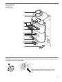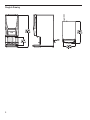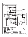
1
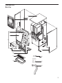
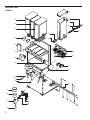
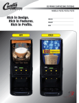
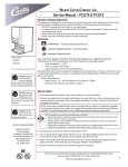
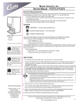
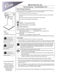
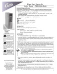
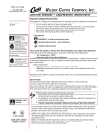
Wilbur Curtis Company, Inc. Service Manual – PCGT3 Important Safeguards/Symbols This appliance is designed for commercial use. Any servicing other than cleaning and routine maintenance should be performed by an authorized Wilbur Curtis Company service technician. • DO NOT immerse the unit in water or any other liquid • To reduce the risk of fire or electric shock, DO NOT open service panels. There are no user serviceable parts inside. • Keep hands and other items away from hot areas of the unit during operation. • Never clean with scouring powders or harsh chemicals. Symbols WARNINGS – To help avoid personal injury Important Notes/Cautions – from the factory Sanitation Requirements ModelsIncluded • PCGT3 STANDARD • PCGT3 PRESET DISPENSE • PCGT3 ICED CAPPUCCINO CAUTION: Equipment must be installed to comply with applicable federal, state, and local plumbing/ electrical codes having jurisdiction. CAUTION: Follow this setup procedure before attempting to use this unit. Failure to follow these instructions can result in injury and/or void of warranty. CAUTION: DO NOT connect the unit to hot water. The inlet valve is not rated for hot water. ISO 9001:2008 REGISTERED WILBUR CURTIS CO. 6913 Acco Street, Montebello, CA 90640-5403 For the latest information go to www.wilburcurtis.com Tel: 800/421-6150 Fax: 323/837-2410 C Your Curtis G3 System is Factory Pre-Set and Ready to Go, Right from the Box. Following are the Factory Settings for your Primo Cappuccino Beverage System: • Tank Temperature = 190°F • Flavor Controls= Set at 60% • Dispensing Mode Set for Manual Dispensing Generally there will never be a reason to change your G3 programming. However, should you need to make slight adjustments to meet your dispensing needs, programming instructions are provided later in this manual. System Requirements: • Water Source 20 – 90 PSI (Minimum Flow Rate of 1 GPM) • Electrical: See electrical schematic on page 7. SETUP STEPS 1. The unit should be level (left to right - front to back), on a secure surface. 2. Connect the water line to the water inlet fitting on the rear of the unit. Water volume going to the machine should be consistent. Use tubing sized sufficiently to provide a minimum flow rate of one gallon per minute. NOTE: Some type of water filtration device must be used to maintain a trouble-free operation. (In areas with extremely hard water, we suggest that a sedimentary and taste & odor filter be installed.) This will prolong the life of your cappuccino system and enhance product taste. NSF International requires the following water connection: 1. A quick disconnect or additional coiled tubing (at least 2x the depth of the unit) so that the machine can be moved for cleaning underneath. 2. This equipment is to be installed with adequate backflow protection to comply with applicable federal, state and local codes.. 3. Water pipe connections and fixtures directly connected to a potable water supply shall be sized, installed and maintained in accordance with federal, state, and local codes. 3. Plug the power cord into an electrical outlet rated at 20A. 4. Turn on power at the toggle switch behind the unit. The lights (display window and row of buttons) on the front door will activate and the heating tank will start to fill. 5. Water in the heating tank will require about one hour to reach operating temperature (factory setting of 190°F). At this time the LCD will display “READY TO DISPENSE”. 6. Remove and fill the canisters with powdered cappuccino product. FOR THE LATEST SPECIFICATIONS AND INFORMATION GO TO WWW.WILBURCURTIS.COM 1 Operation Instructions 1.Choose a flavor. Place your cup under the spout beneath the desired flavor. Note: When using Iced Cappuccino machine, fill your cup with ice before dispensing product. 2.Push and hold the dispensing button for this flavor. 3.Release the button when the cup is ¾ full. FILL CANISTERS DAILY 1. Open the front door to access the product canisters. 2. The canisters must be removed from the unit for filling. Turn the powder delivery elbows clockwise, pointing upward. Pull all of the canisters from the canister tray. 3. Refill the canisters. The small canisters hold five pounds of product. Larger canisters hold 10 pounds each. See Configuration of Canisters on page 6. 3. Reposition the canisters on the canister tray. Properly mate the gear socket with the gear on the motor shaft when aligning canisters. Turn the elbows clockwise, pointing downward. COLD OR HOT? Cleaning the Curtis Primo Cappuccino GT Beverage Dispenser CAUTION - Do not use cleansers, liquid bleach, powders or any other substance containing chlorine. These products promote corrosion and will pit the stainless steel. THE USE OF THESE PRODUCTS WILL VOID YOUR WARRANTY. I. EVERY 3 - 4 HOURS OR MORE OFTEN IF NECESSARY A. Make sure power is ON. STOP/WASH B. Place a container under the dispense spout to catch the rinse water. C. Locate the WASH button on the front control panel. DISPENSE D. Rinse each flavor by pressing and holding the WASH button, while at the same time pressing one of the PUSH dispensing buttons on the control panel. E. Continue holding the WASH button until the water running from the spout runs clear. II.DAILY A. Switch OFF the unit at the power toggle switch, located behind the unit. B. Wipe all exterior surfaces with a damp cloth, removing any spills, residue or dust from the unit. C. Remove both the drip drawer and louvered screen; then wash out its contents. For hard to clean deposits, use a mild, nonabrasive detergent. Rinse with water. D. Wipe and clean the dispensing area with a mild detergent cleaner. III.WEEKLY OR MORE OFTEN IF NECESSARY A.Clean the parts from the whipper assembly. 1. Remove the dispensing nozzle from the whipper chamber. Clean the inside using a narrow brush. 2. Remove the upper mixing cup. Pull cup forward, twist to the left and lift it to separate the upper mixing cup from the lower mixing cup. 3. To remove the lower mixing cup, pull mixing cup up and forward to free it from the hot water inlet fitting. 4. Remove the whipper chamber. Take hold of the whipper chamber. Turn it clock wise to free it from the mounting plate. WASH 5. Pull the whipper propeller from the motor shaft. RINSE 6. Wash, Rinse and Sanitize using a 3-sink method. Air dry all parts. SANITIZE 7. Re-assemble cleaned parts onto the machine. IMPORTANT - When replacing the propeller, make sure it is properly aligned and seated on the motor shaft. The propeller has an embossed ‘D’ to properly align it on the motor shaft. Failure to properly seat the propeller will cause it to fuse with the whipper chamber. This condition will not be covered under warranty. 6. Clean the mounting plate. a. Clean the shaft with a cloth and mild detergent before removing mounting plate. b. Twist the mounting plate clockwise and pull it from the motor shaft. IMPORTANT - Do not remove pillars to take off mounting plate. c. Clean the area behind the mounting plate. d. Clean the water inlet fitting. e. Lubricate the center seal of the mounting plate before reinstalling. 2 Steps to Programming Your Curtis Generation 3 cappuccino dispenser is Factory Pre‑Set for Optimum Performance. Programming for all models is identical except where noted. Entering the Programing Menus Press and hold STOP/WASH for about ten [10] seconds. Display will read Program Menus,(See Illustration). Manual Dispense (Factory Set to Manual Dispense) Press or > to go to Manual Dispense Select. Press ¤ to go to Manual Dispense Select Station. Choose the station and press, the display will read Saving Complete! To select another station for manual dispense, press to go to Manual Dispense Select Station or press > to continue to the next menu. Dispense By Time (Factory Setting OFF) The next screen is Dispense By Time < Select >. Press to select a station. Select the station and the screen will read To Begin Press Push. Press desired dispense button. Hot water will start to dispense and screen will display To Finish Press Push. When Push is pressed, time will be saved and you will exit back to Dispense by Time screen. Continue with additional selections or press > to continue to the next menu. Temperature (Factory set at 190°F – Cold Cappuccino Units Set at 96ºF) Press and screen will show Tank Temperature. Temperature is programmable from 80°F to 204°F in 2‑degree increments. Press < or > to go up or down in degrees. Select desired temperature and then to set. Press > to continue to the next menu. Powder % Ratio (Factory set at 60%) Press and the screen will display Powder % Ratio Select Station. Press desired station. Powder ratio is programmable from 0% (Hot Water) to 100%, in 5% increments. Press < or > to increase or decrease ratio and then press to set. Press > to continue to the next menu. Valves should not be field adjusted to change product strength. Product strength adjustments should be done through programming on the front panel only. Service Call (Factory Set to 1-800-000-0000 x0000) Press to display number and press change number or > to move places and EX to exit when complete This number will be displayed during a Heating system SENSOR ERROR or a WATER ERROR. Press > to continue to the next menu. Banner Name (Factory Set to Curtis) Press to display letters, press to change letters or > to move places and EX to exit when complete. This feature allows up to 14 letters to be programmed for company name or regional name. Programming all blanks disables Banner Name. Press > to continue to the next menu. Model Select Press to select, < or > to select desired model (PC-3, 4, 5) . Press to set and exit program mode. Exit Press to select, exits program mode and returns unit to operation. 3 Parts List Item Nº 1 2 3 3A 3B 4 5 5A 6 6A 7 8 8A 9 9A 10 11 12 13 14 15 16 17 18 19 20 21 22 23 24 25 26 27 28 28A 29 Part Nº WC-58110 WC-68123 CA-1109-01 CA-1148-01² CA-1144-01³ WC-68165-101 CA-1123 CA-1174 CA-1127 CA-1174-101 CA-1101 WC-39958 WC-39618² WC-37126 WC- 795² CA-1173 WC-68160 CA-1160 WC-3518 WC-68121 WC-3503 WC-8591* WC-5310* CA-1030-17* WC-39350-02* WC-39203 WC-13245 CA-1113-06L CA-1112-06 CA-1113-06R CA-1026-03 CA-1065-03 WC-8539 CA-1002-01 WC-5664-05 CA-1051-03 Description Item Nº Part Nº COVER, TOP PCGT3 30 WC-2626-03 PANEL, LEFT SIDE PCGTs 31 CA-1047 FILM, CURTIS LOGO PCGT-3 32 CA-1036 FILM, CURTIS LOGO PRESET DISPENSE 33 WC-37174* FILM, LIGHT BOX ICED CAPPUCCINO 34 WC- 780* DOOR, COMPLETE PCGT3 34A WC- 799² LAMP, 30W 5K CIRCULAR FCL 30 35 WC-8556* LAMP, LED ASSY 11-12W 36VDC 36 WC-3739* LAMP COMPLETE 30W PCGT (INCL BULB) 37 WC-66043 POWER SPLY, (FOR ITEM 5A) 36VDC 38 WC-37123 WINDOW, FRONT CLEAR PCGT-3 39 WC-58121 LABEL ASSY, UCM & DOOR PCGT-3 40 CA-1095 LABEL ASSY, UCM & DOOR PRESET DISP 41 CA-1011-05 KIT, UCM BOARD & LABEL PCGT3 42 WC-43791 CONTROL MODULE, PRESET DISPENSE 43 CA-1005-03 COVER, ALCOVE PCGT-3 44 CA-1009-03 SCREEN, DRIP TRAY PCGT-3 45 CA-1006-06 DRIP TRAY, PLASTIC PCGT-3 46 CA-1037-3Y LEG, GUIDE 3/8”-16 STUD SCREW 47 WC-37118* PANEL, RIGHT SIDE PCGTs 48 WC-66007* LEG, 3/8”-16 STD SCREW BUMPER 49 CA-1024-05 CAPACITOR, X2 ALL ADS MODELS 50 CA-1008-07K* TUBE, 5/16” ID X 1/8”W SILICONE 51 WC-37008* HOSE, EXTRACTOR FAN 17” LONG 52 WC-43067* LABEL, PANEL FLAVOR CURTIS PCGTs 53 WC-5502-01* LABEL, SERVICING INSTRUCTIONS 54 WC-2627* HARNESS ASSY, COMPLETE PCGTs 55 WC-2630* CANISTER ASSY, 10LB LEFT PCGTs 56 WC-3734* CANISTER ASSY, 5LB PCGTs 57 WC-6294 CANISTER ASSY, 10LB RIGHT PCGTs 58 WC- 904-04* ELBOW, PC/CK/HC 59 WC-1438-101 BUSHING, DISCHARGE PC/CK/HC 60 WC- 523* NUT, RETAINER 61 WC- 102* LID, CANISTER 5LB 62 WC- 826L* LID, CANISTER 10LB 63 WC-3765L * SOCKET, GEAR 6mm x 1mm PITCH LHT 64 WC-5231* ² FOR PRESET DISPENSE UNITS ³ FOR ICED CAPPUCCINO * RECOMMENDED PARTS TO STOCK 19 20 4 Description BUSHING, AUGER AUGER, WIRE ASSY GEAR, PLASTIC PC’S USE ON CA-1013 KIT, GEAR MOTOR, CORK BRAKE PCGT CONTROL, POWER MODULE CORK BRAKE UNIVERSAL POWER MODULE PRESET DISP HEAT SINK ASSEMBLY DV PCGTs KIT, WHIPPER MOTOR, SCREWS & INSTR CANISTER TRAY, ASSY PLASTIC PCGT3 KIT, FAN EXTRACT 120V 29 CFM & BRACKET COVER, DUMP VALVE PC-3GT CONNECTOR, ORIFICE WATER PCGT FITTING, BULKHEAD WATER PCGTs RING, MOTOR SHAFT PLASTIC STEAM TRAP PC/CK/HC BOWL, MIXING PC/CK/HC WHIPPER CHAMBER OFFSET PCGTs TUBE, EXTENSION 3.0” LONG YELLOW KIT, WHIPPER PLATE (W/SEAL) 3/PKG SEAL, MOTOR SHAFT PC’S SOFT (20/PKG) PILLAR, LOCATION BLACK KIT, PROPELLER OFFSET BLADES 6/PKG KIT, TANK LID ROUND O-RING, 4-1/2 I.D. x Ø.285 SILICONE PROBE, LIQUID LEVEL BUSHING, CONICAL .583IDx.945ODx.945LG BUSHING, CONICAL BLIND KIT, RPL DUMP VALVE FOR WC-880E PCGTs HEATING TANK, COMPLETE PCGT3 HEATING ELEMENT, 1.6KW W/JAMNUTS SENSOR, TEMPERATURE TANK THERMOSTAT, MNL RESET 120/240V 25A SWITCH, TOGGLE NON LIT 15A 120/240V VALVE, INLET 1 GPM 120V 10W YELLOW KIT, INLET VALVE REPAIR USE ON WC-826L COMPOUND, SILICONE 5 OZ TUBE Illustrated Parts Main View 1 2 3 5 6 7 4 8 9 13 10 14 15 6A 11 12 16 17 18 5 Illustrated Parts Chassis 28 29 27 22 23 30 24 31 26 25 27 34 37 33 32 38 39 35 36 40 41 42 21 43 44 47 45 48 49 50 46 6 Illustrated Parts Heating Tank 51 52 53 54 56 55 57 58 59 60 61 62 63 64 IMPORTANT: Shaft seals should be replaced with the groved side facing outward. Place a dab of food grade lubricant in the rear hole of the seal, as shown below. Before mounting a whipper plate, place a dab of food grade lubricant into the rear, motor shaft hole of the seal. 7 Rough-In Drawing 8 Electrical Diagram 9 Product Warranty Information The Wilbur Curtis Company certifies that its products are free from defects in material and workmanship under normal use. The following limited warranties and conditions apply: 3 Years, Parts and Labor, from Original Date of Purchase on digital control boards. 2 Years, Parts, from Original Date of Purchase on all other electrical components, fittings and tubing. 1 Year, Labor, from Original Date of Purchase on all electrical components, fittings and tubing. Additionally, the Wilbur Curtis Company warrants its Grinding Burrs for Forty (40) months from date of purchase or 40,000 pounds of coffee, whichever comes first. Stainless Steel components are warranted for two (2) years from date of purchase against leaking or pitting and replacement parts are warranted for ninety (90) days from date of purchase or for the remainder of the limited warranty period of the equipment in which the component is installed. All in-warranty service calls must have prior authorization. For Authorization, call the Technical Support Department at 1-800-995-0417. Effective date of this policy is April 1, 2003. Additional conditions may apply. Go to www.wilburcurtis.com to view the full product warranty information. CONDITIONS & EXCEPTIONS The warranty covers original equipment at time of purchase only. The Wilbur Curtis Company, Inc., assumes no responsibility for substitute replacement parts installed on Curtis equipment that have not been purchased from the Wilbur Curtis Company, Inc. The Wilbur Curtis Company will not accept any responsibility if the following conditions are not met. The warranty does not cover and is void under the following circumstances: 1) Improper operation of equipment: The equipment must be used for its designed and intended purpose and function. 2) Improper installation of equipment: This equipment must be installed by a professional technician and must comply with all local electrical, mechanical and plumbing codes. 3) Improper voltage: Equipment must be installed at the voltage stated on the serial plate supplied with this equipment. 4) Improper water supply: This includes, but is not limited to, excessive or low water pressure, and inadequate or fluctuating water flow rate. 5) Adjustments and cleaning: The resetting of safety thermostats and circuit breakers, programming and temperature adjustments are the responsibility of the equipment owner. The owner is responsible for proper cleaning and regular maintenance of this equipment. 6) Damaged in transit: Equipment damaged in transit is the responsibility of the freight company and a claim should be made with the carrier. 7) Abuse or neglect (including failure to periodically clean or remove lime accumulations): Manufacturer is not responsible for variation in equipment operation due to excessive lime or local water conditions. The equipment must be maintained according to the manufacturer’s recommendations. 8) Replacement of items subject to normal use and wear: This shall include, but is not limited to, light bulbs, shear disks, “0” rings, gaskets, silicone tube, canister assemblies, whipper chambers and plates, mixing bowls, agitation assemblies and whipper propellers. 9) Repairs and/or Replacements are subject to our decision that the workmanship or parts were faulty and the defects showed up under normal use. All labor shall be performed during regular working hours. Overtime charges are the responsibility of the owner. Charges incurred by delays, waiting time, or operating restrictions that hinder the service technician’s ability to perform service is the responsibility of the owner of the equipment. This includes institutional and correctional facilities. The Wilbur Curtis Company will allow up to 100 miles, round trip, per in-warranty service call. RETURN MERCHANDISE AUTHORIZATION: All claims under this warranty must be submitted to the Wilbur Curtis Company Technical Support Department prior to performing any repair work or return of this equipment to the factory. All returned equipment must be repackaged properly in the original carton. No units will be accepted if they are damaged in transit due to improper packaging. NO UNITS OR PARTS WILL BE ACCEPTED WITHOUT A RETURN MERCHANDISE AUTHORIZATION (RMA). RMA NUMBER MUST BE MARKED ON THE CARTON OR SHIPPING LABEL. All in-warranty service calls must be performed by an authorized service agent. Call the Wilbur Curtis Technical Support Department to find an agent near you. revA . 6/11/[email protected] . ECN 14151 RevNC . 2/1/[email protected] . EDR 8113 WILBUR CURTIS CO., INC. 6913 Acco St., Montebello, CA 90640-5403 USA Phone: 800/421-6150 Fax: 323-837-2410 Technical Support Phone: 800/995-0417 (M-F 5:30A - 4:00P PST) Web Site: www.wilburcurtis.com 10 E-Mail: [email protected] Printed in U.S.A. 6/12 . F-3845_rev A