1
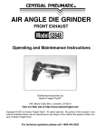
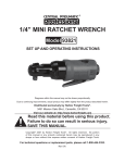
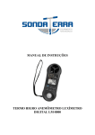
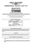
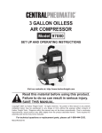
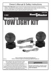
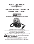
DELUXE 12 VOLT DC LIGHT KIT
Model 93861
3491 Mission Oaks Blvd., Camarillo, CA 93011
Visit our Web site at: http://www.harborfreight.com
TO PREVENT SERIOUS INJURY, READ AND UNDERSTAND ALL WARNINGS AND INSTRUCTIONS.
©
Copyright 2006 by Harbor Freight Tools®. All rights reserved. No portion of this
instruction sheet or any artwork contained herein may be reproduced in any shape or form
without the express written consent of Harbor Freight Tools.
For technical questions, please call 1-800-444-3353.
PRODUCT SPECIFICATIONS
Item
Description
Power Source
12 Volt DC / Negative Ground
Features
2 Combination, Class A, Stop-Tail-Turn Lights
License Plate Bracket
2 Side Marker Clearance Lights
23 Ft., Split Y-Style Harness
4 Ft., Color Coded Trunk Harness
Bulb Types
Stop-Tail-Turn Lights: 12V 21/5W (#1157) / Marker Lights: 12V 5W (#194)
Weight
2.2 Pounds
*Department of Transportation
SAVE THIS INSTRUCTION SHEET
You will need this instruction sheet for the safety warnings and precautions, assembly instructions, parts
list, and assembly diagram. Keep your invoice with this instruction sheet. Write the invoice number on
the front of this instruction sheet. Keep this instruction sheet and invoice in a safe and dry place for future
reference.
UNPACKING
When unpacking, check to make sure all the parts shown on the Assembly Diagram are included. If any
parts are missing or broken, please call Harbor Freight Tools at the number above as soon as possible.
SAFETY WARNINGS AND PRECAUTIONS
1.
Use eye protection. Make sure to wear ANSI approved safety impact eye goggles when installing this Light Kit.
2.
Prior to installing this product, make sure to read and understand all instructions and safety pre-
cautions as outlined in the (trailer, camper, etc.) manufacturer’s manual onto which the Light Kit will be installed.
3.
Maintain the Light Kit. Keep the Light Kit clean and dry for better and safer performance.
4.
DO NOT submerge the Light Kit in water. This Light Kit is NOT waterproof, and will become seriously damaged if submerged in water or other liquids. This product is not intended for marine use.
5.
If necessary, have a qualified service technician install the Light Kit. Do not attempt to install this product yourself if you do not feel technically competent to do so.
6.
Use the right product for the job. There are certain applications for which this product was designed. Do not use small equipment or attachments to do the work of larger industrial equipment or attachments. Do not use this product for a purpose for which it was not intended.
7.
If your trailer, camper, etc. is OVER 80” wide: You will need to install three additional Red Marker
Lights (not included) onto the rear of the unit. To do so, mount the three Red Marker Lights to the rear of the unit, making sure the Lights are no less than 6” and no more than 12” from center of Light to center
of Light. After the Lights are mounted, use wire nut connectors (not included) to connect all three leads
together. Then connect to the Brown wire in the back of one Tail Light (either side) provided in this Kit. (See Assy. Diagram below.)
8.
Replacement parts and accessories: When servicing, use only identical replacement parts. Only use accessories intended for use with this product.
9.
WARNING! People with pacemakers should consult their physician(s) before using this product. Operation of electrical equipment in close proximity to a heart pacemaker could cause interference to or failure of the pacemaker.
10.
WARNING! The warnings and precautions discussed in this manual cannot cover all possible conditions and situations that may occur. It must be understood by the operator that common sense and caution are factors which cannot be built into this product, but must be supplied by the operator.
ASSEMBLY INSTRUCTIONS
Note: Connect the Light Kit after the trailer is fully assembled.
Vehicle Connection:
1.
Connect the BROWN wire of the Color Coded Trunk Harness (5) to the towing vehicle’s Tail Light wire. Connect the YELLOW wire of the Color Coded Trunk Harness to the vehicle’s Left Hand Stop & Turn light. Connect the GREEN wire of the Color Coded Trunk Harness to the vehicle’s Right Hand Stop & Turn light. Make sure to use the BLUE Wire Splitter Connectors to make these connections.
(See Assy. Diagram.)
2.
Attach the WHITE GROUND wire to the towing vehicle’s frame. (See Assy. Diagram.)
3.
NOTE: If the towing vehicle has rear turn signals separated from its stop lights, you will need to install additional hardware.
L.H. STOP & TURN
(YELLOW)
SPLITTER WIRE CONNECTOR
SIDE MARKER
(AMBER)
RIGHT REAR
R.H. STOP & TURN
(GREEN)
BROWN
GREEN
SPLITTER WIRE CONNECTOR
GROUND
(WHITE)
TAIL LICENSE,
SIDE MARKER
(BROWN)
GROUND
(WHITE)
YELLOW
BROWN
SPLITTER WIRE CONNECTOR
SIDE MARKER
(AMBER)
SKU 93861
3 REAR MARKERS
(RED)
REQUIRED
FOR TRAILERS
OVER 80” WIDE
(NOT INCLUDED)
For technical questions, please call 1-800-444-3353
LEFT REAR
&
LICENSE BRACKET
PAGE 2
REV 07k
Trailer Light Mounting And Connection:
1.
Mount the Stop-Tail-Turn Light (1), marked “L.H.” (with the License Window), on the left rear of the trailer with its side marker to the outside of the trailer. Then, mount the License Plate Bracket (3) with the Stop-Tail-Turn Light. (See Assy. Diagram.)
2.
Mount the Stop-Tail-Turn Light (1), marked “R.H.” (without the License Window), on the right rear of the trailer with its side marker to the outside of the trailer. (See Assy. Diagram.)
3.
Use the Metal Frame Clips included in the Mounting Hardware Package (6) to mount each half of the Split Y-Style Harness (4) down each side of the trailer. Run the YELLOW and BROWN wires down the left side and GREEN and BROWN wires down the right side of the trailer. (See Assy. Diagram.)
4.
Connect the YELLOW and BROWN wires to the left hand Stop-Tail-turn Light (1) with the Wire Nut Connectors included in the Mounting Hardware Package (6). (See Assy. Diagram.)
5.
Connect the GREEN and BROWN wires to the right hand Stop-Tail-turn Light (1) with the Wire Nut Connectors included in the Mounting Hardware Package (6). (See Assy. Diagram.)
6.
Attach the WHITE GROUND wire to the trailer tongue or frame. (See Assy. Diagram.)
7.
Mount the two Marker Clearance Lights (2) in the areas shown in the illustration. Connect each wire from the Marker Clearance Lights to the BROWN wire on each half of the Split Y-Style Harness (4).
(See Assy. Diagram.)
8.
Connect the Split Y-Style Harness (4) Plug to the Color Coded Trunk Harness (5) Plug.
(See Assy. Diagram.)
9.
Turn on the towing vehicle’s headlights. The two Stop-Turn-Tail Lights (1) and two Marker Clearance Lights (2) should turn on. The brighter Stop Lights should turn on only when the vehicle’s brake pedal is depressed, or when the vehicle’s turn signal is activated (ignition key must be in its “on” position).
10.
If the Light Kit fails to illuminate, check all ground connections. If the turn signals on the Light Kit do
not illuminate, check the connections between the towing vehicle’s wiring and the Color Coded Trunk Harness (5). (See Assy. Diagram.)
2
2
1
1
3
4, 5
6
(Due to continuing improvements, actual product may differ slightly from the product described herein.)
Part #
Description
Qty
Part #
Description
Qty
1
Stop-Tail-Turn Light
2
4
Split Y-Style Harness
1
2
Marker Clearance Light
2
5
Color Coded Trunk Harness
1
3
License Plate Bracket
1
6
Mounting Hardware (1 package)
1
NOTE: Some parts are listed and shown for illustration purposes only, and are not
available individually as replacement parts.
Maintenance
Monthly check wiring for deterioration; screws for tightness and that bulbs are not burned out.
Replace all problems.
SKU 93861
For technical questions, please call 1-800-444-3353
PAGE 3
LIMITED 90 DAY WARRANTY
Harbor Freight Tools Co. makes every effort to assure that its products meet high quality and durability
standards, and warrants to the original purchaser that this product is free from defects in materials and workmanship
for the period of 90 days from the date of purchase. This warranty does not apply to damage due directly or indirectly,
to misuse, abuse, negligence or accidents, repairs or alterations outside our facilities, criminal activity, improper
installation, normal wear and tear, or to lack of maintenance. We shall in no event be liable for death, injuries to
persons or property, or for incidental, contingent, special or consequential damages arising from the use of our product.
Some states do not allow the exclusion or limitation of incidental or consequential damages, so the above limitation
of exclusion may not apply to you. This warranty is expressly in lieu of all other warranties,
express or implied, including the warranties of merchantability and fitness.
To take advantage of this warranty, the product or part must be returned to us with transportation charges
prepaid. Proof of purchase date and an explanation of the complaint must accompany the merchandise. If our
inspection verifies the defect, we will either repair or replace the product at our election or we may elect to refund
the purchase price if we cannot readily and quickly provide you with a replacement. We will return repaired products
at our expense, but if we determine there is no defect, or that the defect resulted from causes not within the scope
of our warranty, then you must bear the cost of returning the product.
state.
This warranty gives you specific legal rights and you may also have other rights which vary from state to
PLEASE READ THE FOLLOWING CAREFULLY
THE MANUFACTURER AND/OR DISTRIBUTOR HAS PROVIDED THE PARTS LIST AND ASSEMBLY DIAGRAM
IN THIS MANUAL AS A REFERENCE TOOL ONLY. NEITHER THE MANUFACTURER OR DISTRIBUTOR MAKES
ANY REPRESENTATION OR WARRANTY OF ANY KIND TO THE BUYER THAT HE OR SHE IS QUALIFIED TO
REPLACE ANY PARTS OF THE PRODUCT. IN FACT, THE MANUFACTURER AND/OR DISTRIBUTOR EXPRESSLY
STATES THAT ALL REPAIRS AND PARTS REPLACEMENTS SHOULD BE UNDERTAKEN BY CERTIFIED AND
SKU 93861
For technical questions, please call 1-800-444-3353
PAGE 4