1
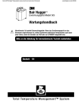
Check the Bair Hugger therapy website to ensure you have the most recent version of this document.
www.bairhugger.com
reorder #200597D
Bair Hugger*
Model 505 Warming Unit
Service Manual
Warning: Electrical Shock Hazard. There are electrically live parts within the
warming unit when it is connected to a power source, even when the switches are
in the OFF or STANDBY position.
Please forward to Biomedical Engineering Department
Bair Hugger Modell 505 Temperaturmanagementgerät Service Gebrauchsanleitung
Vorsicht: Gefährliche elektrische Spannung. In einem an das Stromnetz angeschlossenen
Wärmegerät stehen bestimmte elektrische Komponenten auch dann unter Strom, wenn
der Schalter auf AUS oder BEREITSCHAFTSMODUS geschaltet ist.
Bitte an die Abteilung für biomedizinische Technik weiterleiten
Unité de gestion de température Bair Hugger modèle 505 Service Manuel
Mise en garde : Risque d’électrocution. Certaines pièces sont électriquement chargées
dans les appareils de réchauffement, lorsque ceux-ci sont connectés à une source
d’alimentation et ce, même si l’appareil est en position OFF (arrêt) ou STANDBY (attente).
A transmettre au Service d’ingénierie biomédicale
To t a l Te m p e r a t u r e M a n a g e m e n t S y s t e m
Bair Hugger*
Model 505 Warming Unit
Service Manual
English 1
Deutsch 29
Français 61
Table of Contents
Introduction������������������������������������������������������������������������������������������������������������������������������ 1
Description of the Total Temperature Management* System�������������������������������������������������� 1
Indications�������������������������������������������������������������������������������������������������������������������������������� 1
Contraindications���������������������������������������������������������������������������������������������������������������������� 1
Warnings ���������������������������������������������������������������������������������������������������������������������������������� 2
Cautions������������������������������������������������������������������������������������������������������������������������������������ 3
Notices�������������������������������������������������������������������������������������������������������������������������������������� 3
Read Before Servicing Equipment�������������������������������������������������������������������������������������������� 4
Service Procedures������������������������������������������������������������������������������������������������������������������ 5
Cabinet Cleaning ���������������������������������������������������������������������������������������������������������������������� 5
Hose Replacement�������������������������������������������������������������������������������������������������������������������� 5
Power Fuse Replacement �������������������������������������������������������������������������������������������������������� 6
Control Board Fuse Replacement �������������������������������������������������������������������������������������������� 7
Air Filter Replacement ������������������������������������������������������������������������������������������������������������ 9
Over Heat Alarm Testing �������������������������������������������������������������������������������������������������������� 10
Over Heat Alarm Thermostat Adjustment������������������������������������������������������������������������������ 13
Normal Operating Temperature Testing���������������������������������������������������������������������������������� 15
Normal Operating Temperature Adjustment�������������������������������������������������������������������������� 17
Specifications ������������������������������������������������������������������������������������������������������������������������ 19
Key to Figure 10���������������������������������������������������������������������������������������������������������������������� 20
Technical Support and Customer Service���������������������������������������������������������������������������� 22
When You Call for Technical Support�������������������������������������������������������������������������������������� 22
In-Warranty Repair and Exchange USA���������������������������������������������������������������������������������� 22
Returning Units for Service���������������������������������������������������������������������������������������������������� 23
Troubleshooting���������������������������������������������������������������������������������������������������������������������� 24
Maintenance Log�������������������������������������������������������������������������������������������������������������������� 25
Symbol Definitions ���������������������������������������������������������������������������������������������������������������� 28
Bair Hugger Model 505 Service Manual
Introduction
Description of the Total Temperature Management* System
The Bair Hugger brand Total Temperature Management
system consists of a Bair Hugger forced-air warming unit and
disposable components, including Bair Hugger forced-air
blankets and the 241* blood/fluid warming set, and Bair
Paws* patient warming gowns. The system and disposables are
intended for use in clinical settings including the operating
room. The warming unit draws ambient air through a filter and
warms the air to the specified temperature. It then delivers the
warmed air through a hose to the blanket or gown.
This manual describes how to service the Model 505 warming
unit, and includes maintenance instructions and specifications.
For information about using Bair Hugger blankets, the 241
blood/fluid warming set, or Bair Paws gowns with Bair Hugger
units, refer to the “Instructions for Use” included with each of
these disposable components.
Indications
The Bair Hugger Temperature Management system is intended
to prevent and treat hypothermia. In addition, the temperature
management system can be used to provide patient thermal
comfort when conditions exist that may cause patients to
become too warm or too cold. The temperature management
system can be used with adult and pediatric patients.
Contraindications
Do not apply heat to lower extremities during aortic
cross-clamping. Thermal injury may occur if heat is applied to
ischemic limbs.
Bair Hugger Model 505 Service Manual
1
Warnings
1. Do not leave patients with poor perfusion unmonitored
during prolonged warming therapy sessions. Thermal injury
may result.
2. The Bair Hugger temperature management unit has been
designed to operate safely ONLY with Arizant Healthcare*
disposable components. Use with other products may cause
thermal injury. (To the full extent permitted by law, the
manufacturer and/or importer declines all responsibility
for thermal injury resulting from the unit being used in
conjunction with non-Arizant Healthcare products.)
3. Do not warm patients with the temperature management
unit hose alone. Thermal injury may result. Always connect
the hose to a Bair Hugger blanket or Bair Paws gown before
providing therapy.
4. Do not place the non-perforated side of the blanket on
the patient. Thermal injury may result. Always place the
perforated side (that is, with small holes) towards the patient.
5. Do not continue temperature management therapy if the
over-temp indicator light illuminates and the alarm sounds.
Thermal injury may result. Unplug the unit, and contact a
qualified service technician.
6. Do not continue 241 blood/fluid warming therapy if the
over-temp indicator light illuminates and the alarm sounds.
Immediately stop fluid flow, and discard the blood/fluid
warming set. Unplug the temperature management unit, and
contact a qualified service technician.
7. Do not use a forced-air warming device over transdermal
medication. Increased drug delivery and patient injury or
death may occur.
8. Do not allow the patient to lie on the warming unit hose or
allow the hose to directly contact the patient’s skin during
patient warming; thermal injury may result.
9. Equipment not suitable for use in the presence of a
flammable anesthetic mixture with air or with oxygen or
nitrous oxide.
10. Resuable blankets made from woven fabric, or blankets
without discrete, visible holes, can cause the safety system of
this unit to fail, which may result in serious thermal injury.
This warming unit has been designed to operate safety
ONLY with Bair Hugger blankets and Bair Paws gowns.
2
Bair Hugger Model 505 Service Manual
Cautions
1. Except for specific blanket models, Bair Hugger blankets are
not sterile and are all intended for single patient use ONLY.
Placing a sheet between the Bair Hugger blanket and the
patient does not prevent contamination of this product.
2. Monitor the patient’s temperature and cutaneous response
every 10-20 minutes or according to institutional protocol
and monitor the patient’s vital signs regularly. Adjust air
temperature or discontinue therapy when the therapeutic
goal is reached or if vital sign instability occurs. Notify
physician of vital sign instability immediately.
3. Do not leave pediatric patients unattended during therapy.
4. Do not initiate temperature management therapy unless
the temperature management unit is safely placed on a hard
surface or securely mounted. Otherwise, injury may result.
5. To prevent tipping, clamp the Temperature Management
Unit to an IV pole at a height that provides stability.
We recommend clamping the unit no higher than 44”
(112cm) on an IV pole with a minimum 14” (35cm) radius
wheelbase. Failure to do so may result in IV pole tipping,
catheter site trauma, and patient injury.
6. Electrical shock hazard. Do not disassemble the temperature
management unit unless you are a qualified service
technician. There are electrically live parts with in the unit
when it is connected to a power source, even when the unit
is in Standby mode.
Notices
1. The Bair Hugger temperature management unit meets
medical electronic interference requirements. If radio
frequency interference with other equipment should occur,
connect the unit to a different power source.
2. Federal law (USA) restricts this device to sale by or on the
order of a licensed healthcare professional.
3. To reliably ground this Bair Hugger warming unit, only
connect to receptacles marked “Hospital Only” or “Hospital
Grade”.
Bair Hugger Model 505 Service Manual
3
Read Before Servicing Equipment
The repair, calibration, and servicing of the warming unit
requires the skill of a qualified medical equipment service
technician who is familiar with good practice for medical
device repair. If service is designated as not requiring
manufacturer’s attention, the technical information is provided
in this service manual or will be provided, on request, by
Arizant Healthcare Inc.
Refer to Service Manual
Perform all repairs and maintenance in accordance with the
instructions in this service manual.
Safety Inspection
Perform a safety inspection after making repairs to the
Bair Hugger warming unit and before returning the warming
unit to service. A safety inspection should include a test of the
operating temperatures (described in this service manual), the
Over Heat alarm system, as well as a leakage current test.
Proper Use and Maintenance
Arizant Healthcare Inc. assumes no responsibility for the
reliability, performance, or safety of the equipment if:
• Modifications or repairs are performed by non-authorized
personnel.
• The equipment is used in a manner other than that described
in the Operator’s or Service Manuals.
• The equipment is installed in an environment that does not
meet the relevant grounding requirements.
4
Bair Hugger Model 505 Service Manual
Service Procedures
Cabinet Cleaning
Tools/Equipment
Soft cloth, lightly dampened with water and mild detergent.
Method
1. Disconnect the warming unit from the power source.
2. Wipe the exterior of the warming unit clean.
CAUTION: Do not use a dripping wet cloth when cleaning the
warming unit. Moisture may seep into the electrical contacts
and damage the components. Also, do not use alcohol or other
solvents to clean the cabinet. Solvents may damage the labels and
other plastic parts.
Hose Replacement
Method
1. Press the tab on the blower outlet to release the existing
hose.
2. Attach the replacement hose by inserting the flange end at
a 45° angle in the grooved blower outlet, then snap the hose
into place. (See Figure 1.)
Figure 1. Attaching the
Replacement Hose
Press this
tab to
release
hose
Insert flange into
groove and snap into
place
Bair Hugger Model 505 Service Manual
5
Power Fuse Replacement
The power fuses are located in the power entry module. A
spare fuse is located in the fuse carrier (see Figure 2).
Tools/Equipment
Phillips-head screwdriver
Small slotted screwdriver
Method
1. Disconnect the warming unit from the power source.
2. Remove the 2 Phillips-head screws that secure the cord
retainer. Remove the power cord.
3. Locate the fuse carrier in the center of the power entry
module (see Figure 2).
4. Use the small screwdriver to remove the fuse carrier from
the power entry module.
5. Remove the blown fuse(s) from the fuse carrier.
6. Place the new fuse(s) (as marked) into the fuse carrier.
CAUTION: Replace only with the fuse capacity and type that is
indicated on the adjacent label.
7. Replace the fuse carrier into the power entry module.
8. Reattach the power cord.
9. Replace the 2 Phillips-head screws to reattach the cord
retainer.
10. Reconnect the warming unit to the power source.
11. Record the maintenance action taken and the hours of
operation (read from the hour meter) in the Maintenance
Log section.
Detail
Figure 2. Location
of Power Fuse
Fuse
carrier
Power entry
module (see
detail)
Spare fuse
6
Bair Hugger Model 505 Service Manual
Control Board Fuse Replacement
Control board fuses are located on the control board. (See
Figure 3.) The internal fuses on the Model 505 are for control
board functions only.
The power fuses are located in the power entry module.
Instructions for power fuse replacement can be found in the
Power Fuse Replacement section.
Tools/Equipment
Phillips-head screwdriver
Method
1. Disconnect the warming unit from the power source.
2. Turn the Model 505 unit over, so that the bottom panel is
facing up.
3. Using the Phillips-head screwdriver, remove the screw from
each of the 2 front feet (bumpers) and remove the feet.
4. Remove the Phillips-head screw from the center of the
upper rear panel.
5. Remove the 2 Phillips-head screws located under the bed
hooks on the upper rear panel. Turn the unit right side up.
6. Lift the top cover and unhook the front of the top cover
from the retainer bracket inside. The control panel is
located on the underside of the top cover. See Figure 3 for
location of the fuse.
7. Remove the fuse and replace with the new one.
CAUTION: Replace only with the fuse capacity and type that is
indicated on the adjacent label.
Bair Hugger Model 505 Service Manual
7
Control Board Fuse Replacement
8. Hook the retainer bracket onto the front of the top cover.
9. Place the top cover back into position. Replace all screws.
NOTE: It may be necessary to remove the air filter to correctly
position the lower portion of the retainer bracket inside the
unit.
10. Reconnect the warming unit to the power source.
11. Record the maintenance action taken and the hours of
operation (read from the hour meter) in the Maintenance
Log section.
Figure 3. Location of
Control Board Fuse
Flip the top cover to access the
control board
Phillips screws
Control board
fuse
Retainer bracket
Retainer bracket
hooks into top cover
and is secured by
screws through two
front “feet”
8
Bair Hugger Model 505 Service Manual
Air Filter Replacement
The air filter is mounted in the bottom of the warming unit
(See Figure 4).
Tools/Equipment
Phillips-head screwdriver
Service Frequency
Every 6 months or 500 hours of use.
Method
1. Disconnect the warming unit from the power source.
2. Remove the M6 x 25 pan-head screw on the bottom on the
unit. The filter should slide out easily.
3. Record the hour meter reading and date on the new air
filter label. The hour meter is located in the lower left
corner of the top warning label (see Figure 4).
4. Slide the new filter into the base of the unit.
5. Replace the M6 x 25 pan-head screw on the bottom on the
unit.
6. Reconnect the warming unit to the power source.
7. Record the hour meter reading and maintenance action
taken in the Maintenance Log section.
Figure 4. Location
of Air Filter and
Hour Meter
Hour meter
Air filter
Bair Hugger Model 505 Service Manual
9
Over Heat Alarm Testing
WARNING: Perform all testing and adjustments of warming unit
temperature with a calibrated Model 221 Temperature test kit
or a Model 22110 Temperature test unit. Arizant Healthcare Inc.
assumes no responsibility for the reliability, safety, or performance
of the Bair Hugger system if warming unit temperature testing or
adjustments are made in any other manner than that described
here. Improper measurement or adjustment of the warming
unit’s over heat alarm setting could result in patient exposure to
temperatures outside of the indicated range, and may lead to
patient injury.
NOTE: The Model 221 Temperature Test Kit and the Model 22110
Temperature Test Unit are designed to simulate the operating
characteristics of Bair Hugger blankets and Bair Paws gowns when
used with Bair Hugger warming units; use of the temperature test
device with any other warming system may result in imprecise
readings.
If using the Model 221 Test Kit, temperature readings are taken
from the test kit itself. If using the Model 22110 Test Unit,
temperature readings are taken from a calibrated temperature
meter.
Service Frequency
6-month intervals or 500 hours of use
Tools/Equipment
Phillips-head screwdriver
If using the Model 22110 Temperature Test Unit:
• Use a calibrated temperature meter that can accept a male
subminiature connector and read a K style thermocouple
(e.g., a Fluke Model 52 K/J Thermometer).
• If the connector does not fit your meter, you can remove
the provided connector and attach a connector that fits
your meter.
10
Bair Hugger Model 505 Service Manual
Over Heat Alarm Testing
Method
The Over Heat alarm test panel is located on the back panel of
the Model 505 (see Figure 5).
1. Insert the open hose end from the warming unit in the port
on the temperature test device (see Figure 6).
NOTE: Do not block the rear air vents on the test device.
Figure 6. Model 22110 Temperature Test Unit
Figure 5. Location of Over Heat
Alarm Test Panel
Hose
Port
Test
panel
2. Connect the warming unit to the power source and turn
the warming unit power ON.
NOTE: The temperature setting will not affect the Over Heat
test.
3. Using the Phillips-head screwdriver, remove the screw on
the alarm test panel. The unit will go into an over heat
condition when the test panel is loose.
4. When the over heat alarm activates both visually and
audibly, note the maximum temperature achieved. Let the
alarm operate for at least 1 minute or until the temperature
read-out is approximately 38°C (100°F), then turn the
warming unit OFF and then ON; the alarm should also
turn off. The alarm and manual reset constitutes one cycle.
NOTE: If the alarm does not turn off, allow the unit to alarm for
1 more minute before turning the warming unit to STANDBY,
then ON again.
Bair Hugger Model 505 Service Manual
11
Over Heat Alarm Testing
5. Allow the warming unit to cycle 2 times more after the first
satisfactory reading. When the alarm activates, note the
alarm temperature read-out. See Table 1 for specified limits.
NOTE: The first over heat cycle temperature may be slightly
higher when started from a cold start.
6. If the results of the test did not meet specified limits,
adjust the over heat thermostat. See the Over Heat Alarm
Thermostat Adjustment section.
7. If the results of the test did meet specified limits, turn the
warming unit to STANDBY, and disconnect the warming
unit from the power source.
8. Remove the hose end from the port on the temperature test
device.
9. Retighten the screw on the over heat alarm test panel.
10. Record the maintenance action taken and hours of
operation (read from the hour meter) in the Maintenance
Log section.
Table 1. Over Heat Specification
Model 500 Series High Temperature Thermostat
The thermostat interrupts power to the heater and activates
the alarm at a preset high temperature of 53° ± 3°C
(127.4° ± 5.4°F) or less at the end of the hose, as determined
by the Model 221 Temperature Test Kit or the Model 22110
Temperature Test Unit.
12
Bair Hugger Model 505 Service Manual
Over Heat Alarm Thermostat Adjustment
WARNING: Improper adjustment of the warming unit’s over heat
alarm setpoint could result in patient exposure to temperatures
outside of the indicated range, and may lead to patient injury.
• Closely follow instructions for thermostat adjustment.
• Dangerous voltages are present at the terminals of the
thermostat.
• Always use a Model 221 Temperature Test Kit or a Model 22110
Temperature Test Unit to verify output temperatures.
• Recalibrate the temperature test kit at least once a year. The
Model 22110 Temperature Test Unit does not need to be
calibrated. The meter it is connected to must be calibrated.
Follow the calibration instructions in the meter service manual or
follow standard facility calibration schedules.
• When in doubt, contact Arizant Healthcare Technical Support for
assistance in temperature adjustment.
Tools/Equipment
• Model 221 Temperature Test Kit or a Model 22110
Temperature Test Unit
• Small slotted screwdriver
• Phillips-head screwdriver
Method
1. Insert the open hose end from the warming unit in the port
on the temperature test device.
NOTE: Do not block the rear air vents on the test device.
2. Connect the warming unit to the power source and turn
the warming unit power ON.
NOTE: The temperature setting will not affect the over heat
adjustment.
3. Using the Phillips-head screwdriver, remove the screw on
the alarm test panel. Lift and remove the panel.
Bair Hugger Model 505 Service Manual
13
Over Heat Alarm Thermostat Adjustment
4. Locate the over heat adjustment thermostat (see Figure 7).
NOTE: Adjustment of the over heat alarm thermostat is most
easily done while the temperature read-out is climbing.
5. Use a small slotted screwdriver to adjust the thermostat.
• If the tested alarm temperature was below the specified
limits, turn the screwdriver CLOCKWISE to increase
the alarm temperature.
• If the tested alarm temperature was above specified
limits, turn the screwdriver COUNTERCLOCKWISE
to lower the alarm temperature.
6. Fine-tune the adjustment until the warming unit alarms at
the specified temperature.
7. Manually turn the warming unit to STANDBY, then
ON again. This manual reset constitutes one cycle.
8. Retest the alarm temperature to verify correct adjustment at
least 2 times. Allow the warming unit to cycle before each
test.
9. When the warming unit alarm setting is within the
specified limit, turn the warming unit to STANDBY and
disconnect it from the power source.
10. Remove the hose end from the temperature test device.
11. Replace the over heat alarm test panel. Resecure the screw.
12. Record the maintenance action taken and the hours of
operation (read from the hour meter) in the Maintenance
Log section.
Figure 7. Location of Over
Heat Alarm Thermostat
Over heat alarm
thermostat access
(detail)
14
Bair Hugger Model 505 Service Manual
Normal Operating Temperature Testing
WARNING: Perform all testing and adjustments of warming unit
temperature with a calibrated Model 221 Temperature Test Kit
or a Model 22110 Temperature Test Unit. Arizant Healthcare Inc.
assumes no responsibility for the reliability, safety, or performance
of the Bair Hugger system if warming unit temperature testing or
adjustments are made in any other manner than that described
here. Improper measurement or adjustment of the warming unit’s
normal operating temperature could result in patient exposure
to temperatures outside of the indicated range, and may lead to
patient injury.
Service Frequency
6-month intervals, or 500 hours of use
Tools/Equipment
Model 221 Temperature Test Kit or Model 22110 Temperature
Test Unit
Method
1. Insert the open hose end from the warming unit in the port
on the temperature test device (see Figure 6).
NOTE: Do not block the rear air vents on the test device.
2. Turn the warming unit power ON and select the
HIGH temperature setting. Always begin testing at the
HIGH setting.
3. Note the ambient room temperature.
4. After approximately 5 minutes of operation, note the
temperature read-out. Use Figure 8 to correlate ambient
temperature to the warming unit’s operating temperature.
Figure 8. Room Temperature vs. High
Temperature Output
45
44
43
42
15 16 17 18
19 20 21 22 23 24 25 26
Ambient Room Temperature (°C)
Bair Hugger Model 505 Service Manual
27
At HIGH, Nominal Temperature on Test
Kit (°F)
At HIGH, Nominal Temperature on
Test Kit (°C)
Warming unit temperature setting should be on HIGH when
conducting this test
1
Ambient Room Temperature (°F)
15
Normal Operating Temperature Testing
5. After correcting for ambient temperature, the tested normal
operating temperature should meet the limits specified in
Table 2.
6. If the HIGH temperature setting is not within specified
limits, adjust the normal operating temperature. See the
Normal Operating Temperature Adjustment section.
7. If the HIGH temperature setting is within specified
limits, verify the MED and then LOW settings against
specified limits (allow the warming unit to operate at each
temperature setting for about 3 to 5 minutes
before test).
8. Turn the warming unit to STANDBY. Remove the hose
end from the port on the temperature test device.
9. Record the maintenance action taken and the hours of
operation (read from the hour meter) in the Maintenance
Log section.
Table 2. Model 500 Series Operating Temperatures
(Operating temperature = Average temperature at the end of the hose.)
HIGH: MED: LOW: 43° ± 3°C (109.4° ± 5.4°F)
38° ± 3°C (100.4° ± 5.4°F)
32° ± 3°C (89.6° ± 5.4°F)
Note: Air temperature reaching the patient is approximately 2°C lower than
the listed temperatures.
16
Bair Hugger Model 505 Service Manual
Normal Operating Temperature Adjustment
WARNING: Improper adjustment of the warming unit’s normal
operating temperature could result in patient exposure to
temperatures outside of the indicated range, and may lead to
patient injury.
• Closely follow instructions for temperature adjustment.
• Always use a Model 221 Temperature Test Kit or a Model 22110
Temperature Test Unit to verify output temperatures.
• Always make adjustments relative to the HIGH temperature
setting on the warming unit. When the HIGH setting is accurately
adjusted, the MED and LOW settings should also be within
specified limits. If the HIGH range is properly set, and MED and/
or LOW do not meet specs, call Technical Service.
• Recalibrate the temperature test kit at least once a year. The
Model 22110 Temperature Test Unit does not need to be
calibrated. The meter it is connected to must be calibrated.
Follow the calibration instructions in the meter service manual or
follow standard facility calibration schedules.
• When in doubt, contact Technical Service for assistance in
temperature adjustment.
Tools/Equipment
Model 221 Temperature Test Kit or
Model 22110 Temperature Test Unit
Small slotted screwdriver
Method
The operating temperature adjustment potentiometer may be
accessed through openings in the upper right corner of the rear
access panel (see Figure 9).
1. Insert the open hose end from the warming unit in the port
on the temperature test device.
NOTE: Do not block the rear air vents on the test device.
2. Turn the warming unit power ON, and allow it to operate
at HIGH for about 3 to 5 minutes before adjusting the
potentiometer.
Bair Hugger Model 505 Service Manual
17
Normal Operating Temperature Adjustment
3. Insert the slotted screwdriver in the potentiometer access
hole. You must access the potentiometer blindly, so carefully
move the screwdriver until it fits into the slot of the
potentiometer.
• If the tested operating temperature was below specified
limits, turn the screwdriver CLOCKWISE to increase
the operating temperature.
• If the tested operating temperature was above specified
limits, turn the screwdriver COUNTERCLOCKWISE
to lower the operating temperature.
4. Adjust the potentiometer until the temperature read-out
meets the limits specified in Table 4 for the HIGH
temperature setting (correlated to ambient temperature as in
Figure 8).
5. Verify that the MED and then LOW temperature settings
are also within specified limits. If the HIGH range is
properly set, and MED and/or LOW do not meet specs, call
Technical Service.
6. Turn the warming unit power OFF and remove the hose
from the port on the temperature test device.
7. Record the maintenance action taken and hours of
operation (read from the hour meter) in the Maintenance
Log section.
Figure 9. Location of
Operating Temperature
Adjustment Potentiometer
Operating temperature
potentiometer access
18
Bair Hugger Model 505 Service Manual
Specifications
Physical Characteristics
Electrical Characteristics
Dimensions
13 in. high x 10 in. deep x 11 in. wide
(33 cm high x 25 cm deep x
28 cm wide)
Leakage Current
Weight
11.5 lb (5.2 kg)
Motor
Safety System
Meets regulatory standards for leakage current.
Fractional horsepower, single phase
Heater
Thermostat
An electric heating element
Bulb and capillary type
Fuses
Over Heat Warning
10A, 200mA (110-120 VAC Units)
6.3A, 100mA (220-240 VAC Units)
10, 160mA (100 VAC Units)
If the temperature gets too high, the Over Heat warning
light on the front panel will illuminate and the alarm will
sound. The heat will shut off and the blower will continue
to run.
High Temperature Thermostat
The thermostat interrupts power to the heater and
activates the alarm at a preset high temperature of
53° ± 3°C (127.4° ± 5.4°F) or less at the end of the hose,
as determined by the Model 221 Temperature Test Kit or
Model 22110 Temperature Test Unit.
Device Ratings
110-120 VAC, 60 Hz, 10 Amperes
220-240 VAC, 50 Hz, 4.5 Amperes
100 VAC, 50/60 Hz, 10 Amperes
Temperature Characteristics
Air temperatures reaching the patient are approximately
2°C lower than the listed temperatures.
Operating Temperatures
Average temperature at the end of the hose:
HIGH:
43° ± 3°C (109.4° ± 5.4°F)
MED:
38° ± 3°C (100.4° ± 5.4°F)
LOW:
32° ± 3°C
(89.6° ± 5.4°F)
Bair Hugger Model 505 Service Manual
19
Key to Figure 10
1
2
3
4
5
6
7
8
9
10
Bulb Type Thermostat
Hour Meter
Control Board
Thermocouple
Cabinet
Top Cover
Base Filter, 0.2 Micron
V- Bumper
Heater Housing
11
12
14
15
16
17
18
19
20
21
22
23
24
25
Motor 115V, 60Hz
Heater 120V
Handle
Top Warning Label
Control Board Fuse 200mA
Overtemp Switch
Electrical Shield
Control Panel Label
Back Plate
Power Entry Module
Power Fuses (2)
Filter Bracket
Elbow Assembly
Hose Assembly
20
Bair Hugger Model 505 Service Manual
Figure 10. Exploded Drawing
J2
Detail of Control Board
J1
Bair Hugger Model 505 Service Manual
21
Technical Support and Customer Service
United States, Worldwide
Technical Service
TEL: Order Placement
TEL: FAX: Within Europe
1-952-947-1200
Technical Service 1-800-733-7775
1-952-947-1200
Toll-free in Germany
1-800-733-7775
Order Placement (USA)
1-952-947-1400
TEL: +49-4154-9934-0
FAX: +49-4154-9934-20
0800-100-1236
FAX: +1-952-947-1400
When You Call for Technical Support
We will need to know the serial number of your Bair Hugger unit when you call us. On Model 505 units, the serial
number label is affixed to the rear panel.
In-Warranty Repair and Exchange USA
Replacement parts to correct a problem are delivered at no charge. To return a device to Arizant Healthcare Inc. for service,
first obtain a Return Authorization (RA) number from a technical service representative. Please use this number on all
correspondence when returning a device for service. A shipping carton will be delivered to you at no charge, if needed. We
will service and ship your device within five (5) working days of our receipt. Call your local supplier or sales representative
to inquire about loaner devices while your device is being serviced.
Worldwide
Contact your local distributor concerning in-warranty repair and exchange.
22
Bair Hugger Model 505 Service Manual
Returning Units for Service
Tools/Equipment
•
•
•
•
Arizant Healthcare* service carton
Tape dispenser
Shipping label
Marking pen
Method
1. Call Technical Support (see inside front cover for phone
number) to get a Return Authorization (RA) number and a
service carton.
2. Open the carton and remove the upper foam pad. Leave the
lower foam pad in place in the bottom of the carton.
3. Rotate the hose elbow toward the back of the unit, and
carefully lower the unit into the carton. Place the hose as
shown in Figure 11.
4. Insert the upper foam pad (see Figure 11).
5. Seal the carton with tape.
6. Apply the shipping label addressed to Arizant Healthcare
Inc.
7. Using the marking pen, write your RA number (from
Technical Support) on the outside of the carton.
Figure 11. Service Carton
Upper foam pad
Hose elbow
Lower foam pad
Bair Hugger Model 505 Service Manual
23
Troubleshooting
Call Technical Support for Replacement Parts
Problem
Possible Cause
Remedy; Service Procedure
The warming unit does not turn
on.
Damaged or unplugged power cord.
Replace the cord or plug in the warming
unit.
Blown power fuses
Replace the blown fuses. See Power Fuse
Replacement procedure.
Poor or loose wire connections.
Check the connectors at the power entry
module.
Ensure that connector J1 is firmly seated
(see Figure 10).
No power to outlet.
Check power at the outlet.
Loose cord at power entry cord.
Firmly seat the power module.
The warming unit circulates air
but it does not heat.
Poor connections of the thermocouple
(J2) on the control board. (See Figure
10.)
Reattach any loose thermocouple leads
connections.
The warming unit heats at some
temperature settings but not on
others. Example: the warming unit
works on LOW setting, but not
on HIGH setting.
Loose connection at J2. (See Figure 10) Reattach loose connections.
Warming unit has been in an over
heat condition and temperature has
decreased.
Turn the warming unit OFF and then back
ON.
Loose wire connections at the desired
heat setting.
Reattach any loose connections.
Warming unit alarms upon
startup.
Open thermostat.
Call Technical Service.
Poor wire connections at thermostat.
Reattach any loose connections to
thermostat. (See Figure 10).
Warming unit alarms at too lower
too high a temperature.
Over heat thermostat not in calibration. See Over Heat Alarm Thermostat
Adjustment procedure.
24
Bair Hugger Model 505 Service Manual
Maintenance Log
Date
Maintenance Action Performed
Bair Hugger Model 505 Service Manual
Hour Meter
25
Maintenance Log
Date
26
Maintenance Action Performed
Hour Meter
Bair Hugger Model 505 Service Manual
Maintenance Log
Date
Maintenance Action Performed
Bair Hugger Model 505 Service Manual
Hour Meter
27
Symbol Definitions
ON/STANDBY
ON (used on isolation switch)
OFF (used on isolation switch)
ON/OFF push button switch
Temperature Control
Equipotentiality plug (Ground)
Fuse
!
Attention (see appropriate documents)
Dangerous Voltage
Type BF Equipment (patient applied)
VAC
V
Voltage, Alternating Current (AC)
Special Refuse, discard separately
Protective earth ground
No free hosing
28
Bair Hugger Model 505 Service Manual