1
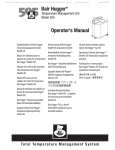
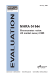
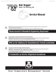
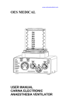
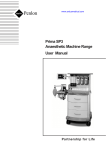
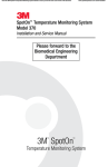
www.ardusmedical.com
Bair Hugger* Model 505 and Model 500/OR
Temperature Management Units
Operator’sManual
Betriebshandbuch für Bair Hugger
Temperaturmanagement-Geräte Modell 505
und 500 OR
Manuel de l’utilisateur pour les appareils
de gestion de la température Bair Hugger
modèle 505 et modèle 500/OR
Manuale d’uso delle unità di gestione della
temperatura Bair Hugger modello 505 e
modelli della serie 500
Manual del usuario para las unidades
de control de temperatura Bair Hugger,
modelos 505 y 500/OR
Manual do utilizador das unidades de gestão
de temperatura Bair Hugger Modelo 505 e
Modelo 500/OR
Bair Hugger Temperatuurregelunits model
505 en model 500/OR Gebruikshandleiding
Brugsanvisning til Bair Hugger temperaturreguleringsenheder, Model 505 og Model
500/OR
Bruksanvisning till Bair Hugger modell 505
och 500/OR temperaturstyrenhet
Brukerhåndbok for Bair Hugger-temperaturbehandlingsenhet, modell 505 og 500/OR
Bair Hugger -lämpötilansäätölaitteen mallit
505 ja 500/OR käyttäjän opas
Bair Hugger Model 505 and Model 500/OR Temperature Management Units
Operator’sManual
1
English
19
Deutsch
37
Français
55
Italiano
73
Español
91
Português
109
Nederlands
127
Dansk
145
Svenska
163
Norsk
181
Suomi
2
English
Bair Hugger Model 505 and Model 500/OR Temperature Management Units Operator’s Manual
Table of Contents
3
Introduction
3
Description of the Total Temperature Management* System
3
Indications for Use
3
Contraindications
3
Warnings
3
Precautions
3
Important Information
4
Read Before Servicing Equipment
4
Setup and Operation
5
Temperature Management Units
6
Control Panel Features of the Model 500/OR Temperature Management Unit
7
Control Panel Features of the Model 505 Temperature Management Unit
8
Mounting the Model 505 Temperature Management Unit
9
Attaching and Storing the Model 505 Hose
9
Isolation Switch
10
Optional Features
11
General Maintenance
11
Cabinet Cleaning
11
Technical Service and Order Placement
12
Specifications
14
Definition of Symbols
Bair Hugger Model 505 and Model 500/OR Temperature Management Units Operator’s Manual
Introduction
Description of the Total Temperature Management System
The Bair Hugger brand Total Temperature Management System consists of a Bair Hugger forced-air
temperature management unit (with available rolling stand and sheet clip) and Bair Hugger disposable components, including forced-air blankets and the 241* blood/fluid warming set. The system is
intended for use in all clinical settings including the operating room.
This manual includes operating instructions and unit specifications for the Model 505 and Model
500/OR forced-air temperature management units. For information about using Bair Hugger blankets or the 241 blood/fluid warming set with Bair Hugger units, refer to the “Instructions for Use”
included with each of these disposable components.
Indications for Use
The Bair Hugger brand Total Temperature Management System is intended to prevent and treat
hypothermia and to provide warmth to cold or shivering patients. In addition, the system should be
used whenever conditions exist that could cause patients to become cold.
Contraindications
Do not apply heat to lower extremities during aortic cross-clamping. Thermal injury may occur if
heat is applied to ischemic limbs.
Warnings
• Do not use Bair Hugger units with any forced-air blanket or cover other than Bair Hugger
blankets. Thermal injury may result.
• Do not warm patients with the Bair Hugger unit hose alone. Thermal injury may result. Always
attach the hose to a Bair Hugger blanket before providing skin surface warming therapy.
• Do not continue therapy if the Over Heat warning light illuminates and the audible alarm sounds.
Thermal injury may result. Turn the temperature management OFF and contact qualified technical
personnel. If using 241 fluid warming, immediately stop fluid flow and discard the fluid warming set.
• Do not initiate therapy unless the Model 505 temperature management unit is securely mounted or
injury may result.
Precautions
• Monitor the patient’s temperature at least every 10 to 20 minutes, and monitor the patient’s vital
signs regularly. Reduce air temperature or discontinue therapy when the therapeutic goal is reached
or if vital sign instability occurs. Notify physician immediately of vital sign instability.
• To prevent suffocation from misuse, do not leave children or infants unattended when administering
Bair Hugger therapy.
• See CONTRAINDICATIONS and WARNINGS before administering therapy. Read this
Operation Manual, blanket instructions and 241 fluid warming set package instructions before use.
Important Information
EXPLOSION HAZARD
Do not use in the presence of flammable anesthetics.
English 3
4
English
Bair Hugger Model 505 and Model 500/OR Temperature Management Units Operator’s Manual
ELECTRICAL SHOCK HAZARD
Do not disassemble the temperature management unit; refer to authorized technical personnel. There
are electrically live parts within the unit when it is connected to the power source, even when the
switches are in the OFF position.
ELECTRICAL INTERFERENCE
If radio frequency interference with monitoring equipment should occur, connect the temperature
management unit to a different power source.
Read Before Servicing Equipment
The repair, calibration, and servicing of the temperature management unit requires the skill of qualified technical personnel who are familiar with good practice for medical device repair. If service is
designated as not requiring the manufacturer’s attention, the technical information is provided in the
Service Manual or will be provided, upon request, by Arizant Healthcare Inc.
REFER TO SERVICE MANUAL
Perform all repairs and maintenance in accordance with the instructions in the Service Manual.
SAFETY INSPECTION
Perform a safety inspection after making repairs to the temperature management unit and before
returning the unit to service. A safety inspection must include a test of the operating temperatures
(described in the Service Manual), the Over Heat Alarm system, as well as a leakage current test.
PROPER USE AND MAINTENANCE
Arizant Healthcare Inc. assumes no responsibility for the reliability, performance, or safety of the
equipment if:
• Modifications or repairs are performed by unauthorized personnel.
• The equipment is used in a manner other than that described in the Operation or Service Manuals.
• The equipment is installed in an environment that does not meet the relevant grounding requirements.
Setup and Operation
The Bair Hugger Total Temperature Management System is easy to set up and to use. Follow the
instructions provided with each blanket for specific information.
1) Place the Bair Hugger blanket on the patient with the perforated side (the side with small holes)
against the patient’s skin.
Figure C.
2) Insert the hose of the temperature management unit in the hose port on the blanket. Use a
twisting motion to ensure a snug fit (see Figure C).
Bair Hugger Model 505 and Model 500/OR Temperature Management Units Operator’s Manual
English 5
3) Connect the unit to a properly grounded power source.
4) If so equipped, turn the Isolation Switch to the ON position (see the section titled Isolation Switch).
5) Press the System ON/OFF button to turn the unit ON and select the appropriate
temperature setting.
6) Place a cotton blanket over the Bair Hugger blanket for maximum effectiveness.
7) Monitor the patient’s temperature at least every 10 to 20 minutes and adjust the temperature
setting of the unit as required.
Folding handle
Figure D. Model 505 temperature
management unit
Figure E. Model 505 unit
attached to an IV pole
Figure F. Model 500/OR temperature
management unit
Temperature Management Units
The temperature management unit uses a high-efficiency motor, a heating element, and a solid-state
temperature control to create a continuous flow of warm air to the blanket. Models 500/OR and 505
are designed for safe use in all areas, including the operating room.
The folding handle on the Model 500/OR unit can be placed in two positions. The handle is moved
forward and down for the folded position; it is pushed up and back for the upright position. In the
folded position the unit can be rolled out of the way (for example, under the operating table) during
warming therapy, and it can be stored more conveniently when warming therapy is completed. The
upright position allows the unit to be easily transported between clinical areas.
The Model 505 temperature management unit can be attached to an IV pole or to the railing on a bed.
6
English
Bair Hugger Model 505 and Model 500/OR Temperature Management Units Operator’s Manual
®
Figure G. Control panel of
the Model 500/OR
temperature management
unit
Control Panel Features of the Model 500/OR Temperature Management Unit
OVER HEAT INDICATOR
The Over Heat Indicator illuminates and an audible alarm sounds when an over-temperature
condition is detected. To reset, turn the unit OFF and then ON, either by the System ON/OFF button (see Figure G), or by the Isolation Switch (see the section titled Isolation Switch. Also refer to the
Warnings section of this manual.)
TEMPERATURE INDICATORS
The indicator bar illuminates up to the selected temperature level. When the unit is initially turned
on, the AMBIENT temperature level is automatically selected.
TEMPERATURE SELECT
Push this button to increase the temperature setting level by level to the desired setting. When the
temperature setting is at HIGH, push the button again to return the setting to AMBIENT.
ON/OFF
Push this button to turn the unit either ON or OFF. The indicator directly above the switch
illuminates when the unit is ON.
SYSTEM
MAIN POWER INDICATOR
The main power indicator illuminates when main power is applied to the unit and the Isolation
Switch is in the ON position (see the section titled Isolation Switch). This indicator must be
illuminated for any functions to operate.
Bair Hugger Model 505 and Model 500/OR Temperature Management Units Operator’s Manual
Figure H. Control panel of the Model 505 unit
Control Panel Features of the Model 505 Temperature Management Unit
TEMPERATURE IN RANGE INDICATOR
The temperature in range indicator illuminates when the output air temperature is within the range
of the selected level.
MAIN POWER INDICATOR
The main power indicator illuminates when the unit is connected to a power source. This indicator
must be illuminated for any functions to operate.
SYSTEM ON/STANDBY
Push this button to turn the unit either ON or OFF. The indicator directly above the switch
illuminates when the unit is ON.
OVER HEAT INDICATOR
The Over Heat Indicator illuminates and an audible alarm sounds when an over-temperature condition
is detected. To reset, turn the unit OFF and then ON, using the System ON/STANDBY button.
(Also refer to the Warnings section of this manual.)
TEMPERATURE INDICATORS
The temperature indicators illuminate up to the selected temperature level. When the unit is initially
turned on, none of these indicators are illuminated and ambient air will be delivered.
TEMPERATURE SELECT
Push this button to increase the temperature setting level by level to the desired setting. When the
English 7
8
English
Bair Hugger Model 505 and Model 500/OR Temperature Management Units Operator’s Manual
temperature setting is at HIGH, push the button again to return to delivery of ambient air.
≤44 inches
Safety strap
>_14 inches
Figure I. Model 505 unit attached to
an IV pole
Figure J. Model 505 unit attached to
a bedrail
Mounting the Model 505 Temperature Management Unit
USING AN IV POLE
The Model 505 unit clamps easily to an IV pole (see Figure I). Simply turn the handle clockwise to
tighten the clamp onto an IV pole, counterclockwise to release.
WARNING: To prevent tipping, clamp the Model 505 unit to an IV pole at a height that
provides stability. We recommend clamping the unit no higher than 44" (112 cm) on an IV pole with a
minimum 14" (35.6 cm) radius wheelbase. Failure to do so may result in IV pole tipping, catheter site
trauma, and patient injury.
USING A BEDRAIL
The Model 505 unit can also hang on the edge of a bed. The safety strap is designed to loop around
the bedrail, keeping the Model 505 unit safely suspended even if the unit is
inadvertently dislodged from the bedrail (see Figure J).
Bair Hugger Model 505 and Model 500/OR Temperature Management Units Operator’s Manual
Insert flange in
groove and snap
into place
English 9
Press this tab
to release hose
Hang hose clip tab
in this slot for storage
Figure K. Attaching the Model 505
unit hose
Figure L. Storing the Model 505 unit hose
Attaching and Storing the Model 505 Unit Hose
The Model 505 unit has a unique “snap-fit” hose. This extended length, swivel hose, adapted for 241
fluid warming, attaches by inserting the flange end at a 45° angle in the grooved blower outlet and
“snapping” the hose into place.
Press the white tab on the blower outlet to release the hose.
When storing the Model 505 unit, insert the hose clip tab in the hanger slot near the blower outlet.
Isolation switch
Figure M. Isolation Switch on the
Model 500/OR unit
Isolation Switch
The isolation switch allows you to disconnect the temperature management unit from the power
source without removing the power cord from the wall receptacle. The isolation switch is located on
the back of the Model 500/OR unit. The isolation switch must be in the ON position before the
unit will operate. The Model 505 unit does not have an isolation switch.
CAUTION: To disconnect the Model 505 unit from the power source, remove the power cord from the
10 English
Bair Hugger Model 505 and Model 500/OR Temperature Management Units Operator’s Manual
wall receptacle. Keep the area around the receptacle clear of obstructions.
Optional Features
This section discusses optional features for Bair Hugger temperature management units. For more
details about these features, please call Arizant Healthcare Inc. or your local distributor.
IV pole
Blanket Dispenser
Figure N. Temperature management
unit with IV pole option
Figure O. Temperature management
unit with blanket dispenser
IV POLE
Model 500/OR unit has a port that accommodates an Arizant Healthcare IV pole.
BLANKET DISPENSER
The blanket dispenser is available for use on the Series 500 units. This dispenser attaches to the unit
and can store several Bair Hugger blankets. See the package instructions for details.
Standard length without swivel option
(replacement only)
Standard length with swivel option
(replacement only)
Extended length with swivel option
(note keyway)
Standard length 241 fluid warming hose
(replacement for 500 series only)
Extended length 241 fluid warming hose
(note keyway) (standard for 500 series only)
Figure P. Hose assemblies
HOSE ASSEMBLIES
Temperature management hose assemblies are available in five options. The keyway on the extended
length hose matches a keyway on units specifically calibrated for the extended length hose option, to
ensure the delivery of proper temperature to the patient.
Model 505 units are only available with a snap-fit extended length 241 fluid warming hose assembly,
Bair Hugger Model 505 and Model 500/OR Temperature Management Units Operator’s Manual
described in Attaching and Storing the Model 505 Warming Unit Hose.
General Maintenance
Cabinet Cleaning
1) Disconnect the temperature management unit from the power source before cleaning.
2) Use a damp soft cloth and a mild detergent to clean the unit cabinet. Dry with a separate soft
cloth.
CAUTION
• Do not use a dripping wet cloth to clean the cabinet. Moisture may seep into the electrical
contacts, damaging the components.
• Do not use alcohol or other solvents to clean the cabinet. Solvents may damage the labels and
other plastic parts.
Technical Service and Order Placement
USA, WORLDWIDE
TEL: 1-952-947-1200
1-800-733-7775
FAX: 1-952-947-1400
WITHIN EUROPE
TEL: +49-4154-9934-0
0800-100-1236 (Toll-free in Germany)
FAX: +49-4154-9934-20
0800-100-1324 (Toll-free in Germany)
In-Warranty Repair and Exchange
Replacement parts to correct a problem are delivered at no charge. To return a device to Arizant
Healthcare Inc. for service, first obtain a Return Authorization (RA) number from a technical service
representative. Please use this number on all correspondence when returning a device for service. A
shipping carton will be delivered to you at no charge, if needed. Call your local supplier or sales representative to inquire about loaner devices while your device is being serviced.
When You Call for Technical Support
Remember, we will need to know the serial number of your unit when you call us. On Model 505
units, the serial number label is affixed to the rear panel. On the Model 500/OR unit the serial number
label is affixed to the galvanized pan on the underside of the unit.
English 11
12 English
Bair Hugger Model 505 and Model 500/OR Temperature Management Units Operator’s Manual
Serial number label
Figure A. Serial number label on
Model 505
Serial number label
Figure B. Serial number label on
Model 500/OR
Specifications
500/OR
505
Physical Characteristics
Physical Characteristics
DIMENSIONS
DIMENSIONS
24 in. high x 16 in. deep x 14 in. wide
61 cm high x 41 cm deep x 36 cm wide
13 in. high x 10 in. deep x 11 in. wide
33 cm high x 25 cm deep x 28 cm wide
WEIGHT
WEIGHT
43 lb; 19.5 kg
13.6 lb; 6.2 kg
MOUNTING
MOUNTING
Supplied with swivel casters; floor use only
IV pole clamp, bedrail hook with safety strap;
can be placed on hard surface
RELATIVE NOISE LEVEL
RELATIVE NOISE LEVEL
52 decibels
53 decibels
HOSE
HOSE
Detachable, flexible, washable; compatible with
Bair Hugger 241 fluid warming system
Detachable, flexible, washable; compatible with
Bair Hugger 241 fluid warming system
FILTRATION SYSTEM
FILTRATION SYSTEM
0.2µM level
0.2µM level
RECOMMENDED FILTER CHANGE
RECOMMENDED FILTER CHANGE
Every 6 months or 500 hours of use
Every 6 months or 500 hours of use
Temperature Characteristics
Temperature Characteristics
TEMPERATURE CONTROL
TEMPERATURE CONTROL
Electronically controlled using a thermocouple sensor
Electronically controlled using a thermocouple sensor
HEAT GENERATED
HEAT GENERATED
1800 BTUs (average)
1800 BTUs (average)
SYSTEM TIME TO
~35 secs
100°F (37.7°C)
SYSTEM TIME TO
~17 secs
100°F (37.7°C)
Bair Hugger Model 505 and Model 500/OR Temperature Management Units Operator’s Manual
English 13
OPERATING TEMPERATURES
OPERATING TEMPERATURES
Air temperatures reaching the patient are approximately 2°C lower than the listed temperatures.
Air temperatures reaching the patient are approximately 2°C lower than the listed temperatures.
Average temperatures at the end of the hose,
assuming the back pressure of a Bair Hugger
warming blanket, or an Arizant Healthcare temperature test unit:
Average temperatures at the end of the hose,
assuming the back pressure of a Bair Hugger
warming blanket, or an Arizant Healthcare temperature test unit:
HIGH: 43° ± 3°C
MED: 38° ± 3°C
LOW: 32° ± 3°C
HIGH: 43° ± 3°C
MED: 38° ± 3°C
LOW: 32° ± 3°C
109.4° ± 5.4°F
100.4° ± 5.4°F
89.6° ± 5.4°F
109.4° ± 5.4°F
100.4° ± 5.4°F
89.6° ± 5.4°F
Safety System
Safety System
THERMOSTAT
THERMOSTAT
Independent bulb and capillary
Independent bulb and capillary
OVERCURRENT PROTECTION
OVERCURRENT PROTECTION
Dual fused input lines
Dual fused input lines
ALARM SYSTEM
ALARM SYSTEM
Over-heat: flashing red light with audible alarm;
heater shuts down
Over-heat: flashing red light with audible alarm;
heater shuts down
CERTIFICATIONS
CERTIFICATIONS
UL 544, CSA C22.2 No. 125, IEC 601-1, IEC
601-1-2, EN55014, AS 3200.1990
UL 544, CSA C22.2 No. 125, IEC 601-1, IEC
601-1-2, EN55014, AS 3200.1990
CLASSIFICATION
CLASSIFICATION
Classified under IEC 601-1 Guidelines as Class I,
Type BF, Ordinary equipment, Continuous operation
Classified under IEC 601-1 Guidelines as Class I,
Type BF, Ordinary equipment, Continuous operation
Electrical Characteristics
Electrical Characteristics
BLOWER MOTOR
BLOWER MOTOR
Operating speed: 2650 rpm
Airflow: 28-30 cfm
Operating speed: 3150 rpm
Airflow: 28-30 cfm
POWER CONSUMPTION
POWER CONSUMPTION
Peak: 1000W
Average: 500W
Peak: 1000W
Average: 450W
LEAKAGE CURRENT
LEAKAGE CURRENT
<100µA
<100µA
HEATING ELEMENT
HEATING ELEMENT
850W Resistive
850W Resistive
POWER CORD
POWER CORD
15-foot, SJT, 3 cond., 10A
4.6 meter, HAR, 3 cond., 10A
15-foot, SJT, 3 cond., 10A
4.6 meter, HAR, 3 cond., 10A
DEVICE RATINGS
DEVICE RATINGS
110-120 VAC, 60 Hz, 9.5 Amperes, or
220-240 VAC, 50 Hz, 4.5 Amperes, or
100 VAC, 50/60 Hz, 10 Amperes
110-120 VAC, 60 Hz, 9.5 Amperes, or
220-240 VAC, 50 Hz, 4.5 Amperes, or
100 VAC, 50/60 Hz, 10 Amperes
FUSES
FUSES
10A, 200mA and 500mA (110 - 120 VAC Units)
6.3A, 100mA and 500mA (220 - 240 VAC Units)
10A, 160mA and 400mA (100 VAC Units)
10A, 200mA and 500mA (110 - 120 VAC Units)
6.3A, 100mA and 500mA (220 - 240 VAC Units)
10A, 160mA and 400mA (100 VAC Units)
DIAGNOSTICS
DIAGNOSTICS
Over-heat test can be performed by the biomedical group.
Over-heat test can be performed by the biomedical group.
14 English
Bair Hugger Model 505 and Model 500/OR Temperature Management Units Operator’s Manual
Definition of Symbols
ON/STANDBY
ON (used on isolation switch)
OFF (used on isolation switch)
ON/OFF push button switch
Temperature Control
Equipotentiality plug (Ground)
Fuse
!
Attention (see appropriate documents)
Non Explosion-Proof
Dangerous Voltage
Type BF Equipment (patient applied)
VAC
V
Voltage, Alternating Current (AC)
0470
Authorized Representative in the European Community
(as defined in Article 14 of the Medical Device Directive: 93/42/EEC):
Actamed Limited, Calder Island Way, Wakefield, WF2 7AW,
United Kingdom • TEL + 44 1924 200550 • FAX + 44 1924 200518
©2003-2004 Arizant Healthcare Inc. All rights reserved.
10393 West 70th Street, Eden Prairie, MN 55344 USA
TEL 800-733-7775 • 952-947-1200 • FAX 800-775-0002 • 952-947-1400
www.arizanthealthcare.com
*Bair Hugger, 241, Total Temperature Management and the Bair Hugger and
Arizant logos are trademarks of Arizant Healthcare Inc., registered or pending
in the U.S. Patent & Trademark Office and in other countries.
Bair Hugger temperature management products may be covered by one or
more of the following patents: US 6,355,915; 6,309,409; 6,309,408;
6,290,716; 6,287,327; 6,254,337; 6,241,755; 6,228,107; 6,210,428;
6,203,567; 6,176,870; 6,168,612; 6,146,412; 6,129,936; 6,126,681;
6,126,393; 6,036,722; 5,997,572; 5,968;084; 5,964,792; 5,928,274;
5,824,025; 5,800,489; 5,773,275; 5,733,318; 5,697,963; 5,674,269;
5,658,325; 5,620,482; 5,545,194; 5,405,371; 5,350,417; 5,336,250;
5,324,320; 5,300,102; 5,300,101; 5,184,612; 5,044,364; 4,572,188. Japan
2,561,326. Canada 1,325,484. EPO 0,311,336. Australia 756,900.
Other patents pending.
200977A
01/04