1
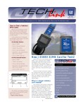
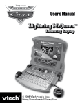
8/23/07
537835 rev.B
©2007, SPX Corporation • Printed in U.S.A • All Rights Reserve
1
SPX KENT-MOORE
Model: J-46079
FCC ID: RP3-J46079
IC: 4811A-J46079
This device complies with part 15 of the FCC Rules and with
RSS-210 of Industry Canada. Operation is subject to the
following two conditions: (1) this device may not cause harmful
interference, and (2) this device must accept any interference
received, including interference that may cause undesired
operation.
The term “IC” before the radio certification number only
signifies that Industry Canada specifications were met.
2
3
General Motors is adding radio frequency (RF) TPM systems on many of their
vehicles. The TPM system consists of a RF transmitting pressure sensor inside
each wheel/tire assembly and a receiver in the vehicle. The receiver receives and
translates the data contained in each sensors transmission into sensor presence,
sensor mode, and tire pressure. The receiver then sends the tire pressure and tire
location data to the instrument panel cluster via the serial data circuit, where the
individual tire pressures and their locations are displayed (on some vehicles) or,
the system will notify the driver if a significant loss of tire pressure has occurred.
The J-46079 TPM diagnostic tool will test the TPM system and can also be used to
activate the sensors (on some vehicles) after a tire rotation, so the receiver can
learn the new sensor locations.
The rechargeable battery pack included in the J-46079-30 kit is recommended for
the J-46079 tool. Three standard rechargeable or alkaline C cell batteries may also
be used. The tool displays its battery level in the upper left hand corner of the main
display.
When using rechargeable batteries J-46079 will ask the question whether alkaline
or rechargeable batteries are installed in the tool. This question has to be answered correctly to display the proper battery level.
Sensor transmission signal strength is displayed in the upper left corner of the
main display next to the tool's battery level display. When the tool is used in both
activate, or scan mode, it will receive the sensor's transmission and indicate its
signal strength. It is important to note the sensor's transmission signal strength after
a sensor is activated by using the TPM diagnostic tool in activate mode, or activated by using the J-41760 sensor activating magnet.
Tire Rotation
It is important that the receiver has learned the correct locations of each tire
pressure sensor so the system indicates the correct location of the tire pressure
condition, as well as sensor location for diagnostic procedures. The sensor learn
procedure must be performed after every tire rotation, sensor replacement, or
receiver replacement.
NOTE: SOME VEHICLE MODEL YEARS REQUIRE THE J-41760 MAGNET TO
ACTIVATE THE SENSORS. THE J-46079 CANNOT ACTIVATE THE SENSORS ON
SOME VEHICLES (CORVETTE, SEVILLE, DEVILLE). REFER TO VEHICLE
SERVICE MANUAL FOR MORE INFORMATION.
1. Enable the tire pressure sensor learn mode in the receiver. Refer to vehicle
service manual for more information.
2. Starting with the left front tire, hold the antenna of the J-46079 TPM tool against
the tire sidewall close to the wheel rim at the valve stem location.
3. Press and release the Activate button. The main display will show moving waves
during activation and then the sensor will transmit. The tool will display the
sensors transmission data and signal strength, a horn chirp will sound within 35 seconds.
4
4. After a horn chirp has sounded, proceed as in step 3 for the remaining 3
sensor in the following order:
o Right front
o Right rear
o Left rear
After all 4 sensors have been learned, exit the learn mode. Refer to vehicle
service manual.
Testing Tire Sensors
The sensor test procedure is used to verify the sensors can transmit valid data
after they have been activated with a Low Frequency (LF) transmission from the
J-46079 TPM tool, or activated with the J-41760 magnet. This test cannot verify if
the sensors internal roll switch is functioning properly, for that, a test drive is
necessary. Refer to vehicle service manual for further diagnostic information.
During this procedure the J-46079 TPM tool will receive sensor transmissions
and display the transmission data on the screen.
NOTE: DEPENDING ON THE VEHICLE MODEL YEAR, THERE ARE TWO WAYS
TO ACTIVATE THE SENSOR.
Model year 2003 and some 2004 (Corvette, Seville, Deville) use magnetic
activation:
1. Press and release the Scan button on the tool. The circling symbol indicates
the tool is scanning for the sensor's transmission.
2. Hold the J-41760 magnet over a valve stem to activate the sensor.
\3. With the J-46079 TPM tool, observe the screen and wait 3-5 seconds for the
sensor's transmission to be received. The screen should display an 8-digit ID
number, tire pressure within 2 psi of actual tire pressure, learn
mode and good signal strength.
4. Proceed as in step 3 for the remaining sensors to verify all sensors are
operating properly.
Model year 2004 or greater (Low Frequency (LF) activation):
1. Hold the antenna of the J-46079 TPM tool against the tire sidewall close to the
wheel rim at the valve stem location.
2. Press and release the Activate button on the tool. The circling symbol
indicates the tool is scanning for the sensor's transmission.
\3. With the J-46079, observe the screen and wait 3-5 seconds for the sensor's
transmission to be received. The screen should display an 8-digit ID number,
tire pressure within 2 psi of actual tire pressure, learn mode and good signal
strength.
4. Proceed as in step 3 for the remaining sensors to verify all sensors are
operating properly.
NOTE: SENSOR TRANSMISSION DATA DISPLAYED ON THE TOOL SCREEN
IS ERASED EACH TIME THE ACTIVATE, OR SCAN BUTTONS ARE PRESSED.
5
Testing Receivers
The receiver test procedure is used to verify the receiver can receive and
translate the data from simulated sensor transmissions.
1. Enable the learn mode in the receiver. Refer to vehicle service manual
for more information.
2. Locate the J-46079 in a central location in the passenger compartment
of the vehicle.
3. Press and release the Simulate button.
4. Press and release the Start button.
5. Press and hold the Simulate button and the J-46079 will begin to
transmit a simulated sensor transmission. When the receiver receives
the simulated sensor transmission a horn chirp will sound, or the DIC
will display the next sensor to be learned.
6. Release the Simulate button. Press and release Yes button after a
horn chirp has sounded, or DIC message is displayed.
7. Proceed as in step 5 for the remaining 3 sensor locations until all 4
simulated sensor transmissions have been learned into the receiver’s
memory. The J-46079 will display the preset Id numbers and tire
pressures for each location.
8. With the scan tool, observe the TPM data list and verify the sensor
Ids and tire pressures match what is displayed on the J-46079 screen
and all 4 sensor modes are “Learn”.
NOTE: ON MODEL YEAR 2001-2004 SEVILLE AND CORVETTE, AND 20012005 DEVILLE, THE SCAN TOOL DOES NOT DISPLAY THE SENSOR ID'S, OR
MODE AND CAN ONLY BE USED TO VERIFY TIRE PRESSURE/LOCATION
DATA.
6
TPM System Diagnostic Aids
The J-46079 does not receive a
sensor transmission after a
sensor has been activated.
After activating a sensor with
either the J-46079, or J-41760,
the sensor mode in the transmission received was not "Learn".
Hold the tool's antenna within 6 inches of
the sensor when activating a sensor. This
process may need to be repeated up to 3
times. If a sensor continues to not respond,
refer to the vehicle service manual for
further diagnostic, or repair information.
The tool has received a random transmission from another sensor on the vehicle, or
from a sensor on another vehicle. The mode
displayed should always be "learn" when
the sensor is activated with the either J46079, or J-41760.
A sensor DTC is set and current
in the vehicle's receiver but after
performing the tire pressure
sensor test the J-46079 is
indicating a malfunctioning
sensor in a different physical
location than the DTC's descriptor.
The sensor Ids and their last learned
locations noted in the scan tool's TPM data
list (on some vehicles) can be compared to
the Ids and physical locations noted with
the J-46079 display to determine if the
sensors have become mis-located due to a
previous tire rotation where the sensor
learn procedure was not performed.
When performing the receiver
test, the vehicle's receiver does
not learn the simulated sensor
transmissions from the J-46079.
Locate the tool closer to the receiver and
repeat the simulation test, also verify the
vehicle's horn is functioning.
After the receiver test, the preset
tire pressures displayed on the J46079 screen do not exactly
match the tire pressures displayed on either the vehicle's
DIC, or the scan tool's TPM data
list.
Since some vehicle receivers compensate
for barometric pressure, the tire pressures
displayed on the scan tool and the DIC can
differ as much as 4 psi from the preset tire
pressures displayed on the J-46079 screen.
The receiver test is intended to verify the
receiver's ability to receive a simulated
sensor transmission and not necessarily its
ability to accurately translate pressure data.
7
Battery Charger
This guide presents the setup, use, maintenance and troubleshooting of the
charger along with a method to optimize your batteries.
Desktop
Place the charger on a solid, level surface that is free of debris (for additional
information on Safety Guidelines see page 6). Ensure the power cord is
unobstructed to prevent damage, stress or injury.
Parts of the Tire Pressure Monitor Charger
Legend
1. Battery Charger
2. Battery Status Display
3. Contacts
4. Power Supply
5. Power Cord
Safety Guidelines
Before using the battery charger, read all instructions and cautionary markings
on the battery charger, battery, and on any product that uses the battery.
WARNING
To reduce risk of injury, use this charger only with authorized products. Other
batteries or adapters may cause personal injury and/or damage.
• When securing the power cord, do not pierce rubber insulation. This may
cause damage or personal injury.
• Do not expose the charger to rain, snow or direct sunlight.
• Use the charger at room temperature 20°C (68°F) to 25°C (77°F).
• Place the charger in a well-ventilated area free of foreign objects/matter.
• To reduce risk of electric shock, unplug the charger from the outlet before
cleaning or changing adapters.
• Dispose of used batteries in accordance with local hazardous material
laws.
• Do not disassemble, incinerate, modify or short circuit batteries, charger or
related components.
Only UL listed power supply marked Class 2 or listed to UL 1950 with SELV
outputs should be used with this product. Refer to voltage rating on the product
label for correct selection.
New Batteries
When charging battery packs that are new or have been on a shelf for an
extended period of time, the charger may prematurely switch to ready. Perform
a battery conditioning cycle on all new NiCd/NiMH batteries before use to
ensure the battery is completely and properly charged.
8
Power Supply Connection
WARNING
• Never alter an AC cord or its plug. If it does not fit into your outlet, have a
proper outlet installed by a qualified electrician. An improper connection can
cause an electric shock.
• To reduce the risk of electric shock, the charger must be grounded.
The power supply uses a nominal 115 or 230 volt circuit with a grounding plug
that fits one of the outlets shown below. Insert the grounding plug into an outlet
that is properly installed and grounded, in compliance with all local codes and
ordinances.
A temporary adapter can be used to connect the grounding plug to a properly
grounded two-prong outlet. A 115-volt adapter is shown in Figure 3. Connect
the grounding plug on the adapter to the outlet box using the cover plate screw.
Use the temporary adapter only until a properly grounded, three-prong outlet
can be installed by a qualified electrician.
WARNING
• Before using an adapter, ensure that the outlet box is grounded. If you are
not sure the box is grounded, have it checked and repaired, if necessary, by
a qualified electrician.
The power supply manages and conditions the power input to the charger. This
device negates the need for a resettable or replaceable fuse. If a power surge
occurs the power supply temporarily interrupts the current supply until the
condition is corrected. If the power light on the power supply fails to light an
extreme surge may have occurred, and the power supply may trigger an
internal fuse that must be serviced by the manufacturer. Return the power
supply for repair or replacement immediately.
9
NiCD/NiMH*
Power:
Solid green when
power is available.
Ready, Standby or
Fault:
Solid green when
battery is ready.
Flashing yellow if
battery is on standby.
Solid yellow if a
battery is rejected.
Charging:
Solid yellow when
battery is charging.
Charging the Battery
Insert the battery into the charger. When the battery is inserted, the charging
system begins the rapid charge cycle. When this cycle is completed, the
"READY" indicator on the Battery Status Display turns solid green, and the
battery is charged to approximately 95% of its rated capacity. To attain 100% of
its capacity the battery should remain in the charger for 3 hours. A charged
battery may be stored in the charger indefinitely.
Upon completion of the charging cycle, the charger switches to "Maintenance
Mode" where it maintains the battery at 100% of its rated capacity.
CAUTION: Do not charge a battery that is below 0°C (32°F). Allow the battery to
warm up to room temperature before charging.
Note: The operating temperature of the device is 0°C (32°F) - 50°C (131°F).
Charge batteries at room temperature 20°C - 25°C (68°F - 77°F). Batteries that
are charged in conditions that are above or below room temperature will exhibit
battery cycle life and capacity below their rated values. This also applies to the
temperature of the battery itself. Allow batteries that are below 20°C (68°F) or
above 25°C (77°F) to adjust to room temperature before charging.
10
Battery Rejection
If the Fault indicator on the Battery Status Display flashes (see Figure 4) and is
not in condition, the battery is faulty or damaged. If the battery is still within its
warranty period, contact the original manufacturer of the battery pack.
See Troubleshooting table for actions to be taken. If the rejected indicator
continues to flash the battery should be removed and disposed of properly.
Conditioning the Battery
To condition a battery exhibiting a decrease in capacity, insert the battery into
the charger and hold down the "CONDITION" cycle button for two seconds (see
Figure 4). The charger performs a complete (100%) discharge of the battery and
recharges it to full available capacity, eliminating conditions that may cause it to
perform below its rated capacity. This deep discharge cycle may take up to 20
hours to complete.
Note: This cycle should only be used on NiCD/NiMH batteries and only once
every several weeks. Performing the conditioning cycle on a daily or weekly
basis shortens the usable life of the battery.
If conditioning the battery fails to eliminate the problem, your battery may have
exceeded its usable life and may need replacement. Most batteries have a
usable life of approximately 500 charge/discharge cycles. This number varies
depending on use and battery cell manufacturer.
Troubleshooting
Symptom/Situation
Probable Cause
Corrective Action/Solution
Power indicator is not lit/
displayed.
Bad charger.
Faulty LED.
Do not use charger.
Return for repair.
Try another charger.
Battery Rejected indicator is
displayed. (Yellow flashing)
Faulty condition identified.
Remove battery from
charger and reinsert.
Allow to sit in charger for
15 minutes, then reinsert.
Replace battery.
Over discharge of battery.
Defective Battery.
Charger goes to ready in a
short period of time.
(10-15 minutes)
Battery is fully charged.
Faulty battery.
New Battery.
Charger will not go into
Charge mode. (Yellow solid
indicator)
Bad charger.
Defective battery.
Battery too cold or hot.
Faulty LED.
Charger will not go into
Condition mode.
(Yellow solid indicator)
Battery too hot.
Battery already discharged.
Faulty LED.
Try conditioning battery.
Replace battery.
Remove battery from charger
and reinsert.
This may take 3-4 cycles to
adequately form new battery
packs.
Replace charger.
Replace battery.
Allow to adjust to ambient
room temperature.
Send in for repair.
Remove battery.
Allow battery to charge
and try condition again.
Send in for repair.
Battery becomes hot
Defective battery.
Immediately remove battery
from charger and replace.
Power supply shuts
down temporarily
Power line surge.
Power will automatically
reset.
11
Battery Charger
This Appliance is a Class 1 LED Device
Radio Frequency Interference Requirements - United States
This device has been tested and found to comply with the limits for a Class A device
pursuant to Part 15 of the Federal Communications Commissions Rules and Regulations.
These limits are designed to provide reasonable protection against harmful interference
when the equipment is operated in a commercial environment. This equipment generates,
uses, and can radiate radio frequency energy and, if not installed and used in accordance with the instruction manual, may cause harmful interference to radio communications. Operation of this equipment in a residential area is likely to cause harmful interference in which case the user will be required to correct the interference at his own
expense.
However, there is no guarantee that interference will not occur in a particular installation.
If the equipment does cause harmful interference to radio or television reception, which
can be determined by turning the equipment off and on, the user is encouraged to try to
correct the interference by one or more of the following measures:
•
•
•
•
Reorient or relocate the receiving antenna.
Increase the separation between the equipment and receiver.
Connect the equipment into an outlet on a circuit different from that which the receiver
is connected.
Consult the dealer or an experienced radio/TV technician for help.
Radio Frequency Interference Requirements - Canada
This Class A digital apparatus meets the requirements of the Canadian InterferenceCausing Equipment Regulations.
CE Marking and European Union Compliance
Products intended for sale within the European Union are marked with the CE Mark which
indicates compliance to applicable Directives and European Normes (EN), as follows.
Any amendments to these Directives of ENs are included:
Applicable Directives:
•
•
Electromagnetic Compatibility Directive 89/336/EEC
Low Voltage Directive 73/23/EEC
Applicable Standards:
•
•
•
•
•
•
12
EN 55 022 - Limits and Methods of Measurement of Radio Interference Characteristics of Information Technology Equipment
EN 50 082-1 - Electromagnetic Compatibility - Generic Immunity Standard, Part 1:
Residential, Commercial, Light Industry
IEC 1000-4-2 - Electromagnetic Compatibility for Industrial Process Measurement and
Control Equipment Part 2: Electrostatic Discharge Requirements
IEC 1000-4-3 - Electromagnetic Compatibility for Industrial Process Measurement and
Control Equipment Part 3: Radiated Electromagnetic Field Requirements
IEC 1000-4-4 - Electromagnetic Compatibility for Industrial Process Measurement and
Control Equipment Part 4:Electrical Fast Transients Requirements
EN 60 950 -1:2001 - Safety of Information Technology Equipment Including Electrical
Business Equipment.
Technical Service
Telephone: 1-800-GMTOOLS
13
14