1
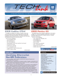
July 2009
Volume 11, No.7
A Monthly Publication for GM Dealership Service Professionals
All-New
2010
Cadillac SRX
The all-new 2010 Cadillac SRX midsize
crossover represents a significant departure from
its rear-drive predecessor as a more integrated
and highly styled entry. It’s based on General
Motors’ all-new global midsize front-drive
crossover architecture (also called Theta-Epsilon).
The new SRX has a dramatic presence — from
its prominent shield grille and large, center-positioned wreath and crest to the vertically oriented,
contemporary “tailfin” taillamps that incorporate
more than 40 LEDs per lamp.
Global-A Serial Data Electrical
The SRX uses the GM Global-A Serial Data
Electrical Architecture – a high-and low-speed data
network that connects system modules.
The Body Control Module (BCM) is the heart
of the electrical system, acting as a gateway
between the high-speed and low-speed data
buses.
TIP: You will use the MDI with GDS software and a laptop PC in place of the
Tech 2 for diagnosis.
Passive Entry and Passive Start Systems
The optional Passive Entry System enables operation of the doors, ignition
and liftgate without removing the transmitter from a pocket
continued on page 2
Techline News
VIN Structure Change for 2010
Several changes are being made to the numbering structure for VINs (Vehicle
Identification Numbers) for both trucks and cars, beginning with the 2010 model
year. See the accompanying illustrations.
The VIN structure was instituted by all vehicle makers in 1981 in compliance
with government regulatory requirements. The VIN contains standardized data
required by government and insurance agencies.
TRUCKS and MPVs
For LD trucks and multi-purpose vehicles (MPVs), beginning with 2010,
there is a new requirement for the VIN to identify the restraint system devices
and locations. Position 7 will be used for this purpose (it formerly indicated
Body Type).
TIP: Previously, position 7 Restraint System was not common between trucks
and cars. Now, it is.
Position 4 previously indicated GVWR/Brake Systems and now indicates
GVWR/Brake Systems and Body Style.
Positions 4, 5 and 6 are now alpha-numeric and position 7 is alpha only. This
increases the number of systems that can be described with a single character.
See the accompanying illustrations on page 4.
continued on page 4
July 2009
1
Contents
All-New 2010 Cadillac SRX . . . . . . . . . . .1
VIN Structure Change for 2010 . . . . . . . .1
USB Control of Multimedia Systems . . . . .4
Navigation Display Squeaks . . . . . . . . . . .5
Key Sticks in Ignition . . . . . . . . . . . . . . . .5
Body Side Moldings . . . . . . . . . . . . . . . .5
Locking Lug Nut Kit . . . . . . . . . . . . . . . .5
Transmission Cooler Line Leak . . . . . . . . .5
Tire Pressure Monitor Tips . . . . . . . . . . .6
Tire Pressure Monitor Tester
Update Kit . . . . . . . . . . . . . . . . . . . . . . .6
Convertible Top Window Operation . . . . . .6
Service Trailer Brake Message . . . . . . . . .6
Out of Fuel – 1/4 Tank . . . . . . . . . . . . . .7
Inoperative Camera . . . . . . . . . . . . . . . .7
BCM Programming Tips . . . . . . . . . . . . .7
Fix It Right the First Time . . . . . . . . . . . .8
Know How Broadcasts for August . . . . . .8
Service and Parts Operations
All New 2010 Cadillac SRX
Passive Entry System lock sensor
or purse. With the transmitter within 3
feet (1m) of the doors, the driver’s door
or all doors will unlock automatically
when any door handle is pulled.
All doors will lock automatically when
the ignition is off, the transmitter is
removed from the vehicle, all doors are
closed, and the lock sensor on a front
door handle is pressed.
TIP: From inside the vehicle, when the
door is locked, it is necessary to pull the
inside handle TWICE – first to unlock,
second to release the door latch.
The standard Passive Start System
features a START/STOP button on the
instrument panel to start the engine. The
vehicle must be in Park or Neutral with
the brake pedal depressed. When the
engine starts, the indicator on the button
will illuminate green.
The Passive Start System is standard
equipment on the 2010 SRX.
TIP: If the transmitter battery is weak,
insert the transmitter into the slot above
the Accessory Power Outlet in the center
console lower storage area to enable the
engine to start.
To turn off the engine, shift to Park and
press the START/STOP button. Power to
the audio system, windows and sunroof
will be active for 10 minutes or until a
front door is opened.
With the engine off and the brake
pedal NOT depressed:
– Press the START/STOP button to
place the ignition system in the
Accessory position. The yellow
indicator will illuminate.
– Press the button again to place the
ignition in the On position. The
instrument cluster and the green
indicator will illuminate.
– Press the button once more to
return to the Off position.
– continued from page 1
The systems work via six ferrite stick
antennas located in each of the front
door handles; the center console rear of
the shifter; underneath the instrument
panel; in the cargo area; and within the
rear bumper of the vehicles. The antennas determine whether the transmitter
is in or out of the vehicle. Upon pulling
any exterior door handle, or pressing the
liftgate access button, the closest antenna within the vehicle wirelessly interacts
with the transmitter, and within 260
milliseconds, authorizes the identity of
the driver and allows vehicle entry.
Powertrains
There are two powertrain combinations
available on the SRX.
3.0L DOHC DI VVT
V6 engine
The base 3.0L DOHC DI VVT V6 engine
(RPO LF1) produces 265 horsepower
(198 kW) and 223 lb.-ft. (302 Nm) of
torque and is mated to the 6T70 HydraMatic six-speed automatic transmission.
The 3.0L direct injection V-6 is a smallerdisplacement version of the 3.6L, direct
injection engine featured in the CTS
sedan. The DI VVT V6 engine employs
four-cam phasing to change the timing of
valve operation as RPM and engine load
vary for a linear delivery of torque, with
near-peak levels over a broad RPM range
while reducing emissions.
Driver’s also can use the Fuel Economy
(Eco) mode on turbocharged V6 models,
activated by pressing the ECO button
next to the shift lever, to help improve
the vehicle’s fuel economy. When active,
the Eco mode changes the transmission
shift points and makes several other fuelsaving adjustments. This changes the
vehicle’s performance and results in a
more conservative driving characteristic.
Towing Capacities
RPO V92 includes the following towing
provisions on the SRX:
– Hitch
– Harness
– Rear fascia closeout
– Auxiliary transmission oil cooler
An SPO accessory trailer hitch package
also is available that includes the same
components as RPO V92.
The SRX’s trailer towing maximums
when properly equipped:
– 3.0L V6 – 2500 lbs./1136 kg (without
auxiliary transmission oil cooler)
– 3.0L V6 – 3500 lbs./1590 kg (with
towing package)
– 2.8L V6 – 3500 lbs./1590 kg
All-Wheel-Drive System
The electronically controlled, ondemand all-wheel-drive system provides
power to the front wheels during normal
driving on dry road surfaces. If the front
wheels slip, power is automatically
delivered to the rear wheels as well.
The system includes a power takeoff
unit attached to the transaxle, a threepiece propeller shaft, a compact Rear
Drive Control Module (RDCM), and an
Electronic Limited Slip Differential
(ELSD) system.
The limited slip differential clutch is a
disc type that is electro-hydraulically
controlled by the rear drive control module (RDCM) via a pressure control valve
fitted on the differential clutch housing.
The disc pack separately distributes the
torque between the rear wheels. The
disc pack is compressed by an operating
piston that is controlled by the RDCM.
Tire Sealant and
Compressor Kit
2.8L DOHC VVT
turbo V6 engine
The 2.8L DOHC VVT turbo V6 engine
(RPO LAU) with the AF40 Aisin-Warner
six-speed automatic transmission is
optional and will be available in late 2009.
The turbo V6 engine generates 300
horsepower (224 kW) and 295 lb.-ft. (400
Nm) of torque.
2
The SRX does not have a spare tire
as standard equipment. The tire sealant
and compressor kit can be used to
temporarily seal small punctures in the
tread area of a flat tire. The kit is located
in the rear storage compartment of the
cargo management system. Refer to the
kit instructions for complete operating
information.
Electronic Suspension Control
The ZF Sachs electronic suspension
control system (RPO F45), individually
July 2009
changes the damping force of each of
the shock absorbers within milliseconds.
Suspension characteristics can be
changed at any time by activating the
Sport mode or Tour mode through the
gear shifter’s position. The suspension
control module evaluates various sensor
inputs in order to separately control the
damping forces of the shock absorbers.
Infotainment and Navigation
Thanks to the
separation of
“silver box”
control modules
from relating
instrument panelmounted control
interfaces, the
new SRX has a
contemporary
Integrated Center
Stack (ICS)
SRX Integrated
design, free of
Center Stack
the stacking of
radio/HVAC/display component boxes.
The Navigation System incorporates a
satellite-based enhanced HDD-based
Navigation. A DVD is not required for the
navigation database due to the 40 GB
hard drive storage.
Through a USB jack located in the
vehicle’s center console, digital audio
music files – such as MP3, WMA, M4A,
and ACC files – can be downloaded to
the hard drive for storage and playback.
TIP: The USB jack provides true iPod®
capability, enabling recharging and control
of the iPod. However, not all iPod devices
are compatible, in which case it’s necessary to use the AUX jack.
Front/Rear Park Assist
The system uses four bezel-less
integrated sensors on the front and rear
fascias to help avoid colliding with
objects when parking the vehicle at
speeds less than 5 mph (8 km/h).
Detected objects are indicated by
audible beeps. The interval between the
beeps becomes shorter as the vehicle
gets closer to an object. A distance
display in the instrument cluster also indicates when objects up to 4 feet (1.2m) in
front of the vehicle are detected. There is
no rear distance display on the headliner.
The system can be turned on/off by
pressing the Parking Assist button next
to the shift lever.
Off Mode (Disable) – Power is
disabled. The liftgate will operate as a
manual liftgate.
TIP: Manual effort is higher than with a
standard non-power liftgate.
3/4 Mode (Programmable) – The
liftgate powers open to a height programmed by the owner (to prevent the
liftgate from hitting overhead obstructions or to make it easier to reach the
liftgate when open).
Max Mode (Full Open) – The liftgate
will power open to the full open height.
To program the memory height,
manually open the liftgate to the desired
height, and then press and hold the
button on the liftgate adjacent to the
latch until the
taillamps flash
and a beep
sounds, which
indicates that
the setting is
stored. Be sure
to turn the
power liftgate
switch to the
3/4 Mode position to have the
The power liftgate can
liftgate open to
be programmed to open
to a specific height.
the programmed
height.
Power Folding Mirrors
To fold or unfold the power mirrors,
place the power mirrors selector switch
in the middle position and then press the
down arrow on the control switch.
TIP: The power mirrors should be
folded before entering an automatic
car wash. If the power mirrors are folded/unfolded manually, they will have to
be reset. Otherwise, they may not function properly or may vibrate while driving.
Follow the Owner Manual procedure for
resetting the power mirrors.
Memory Seats
The memory seats function allows
the driver to set the seat, power outside
mirrors and adjustable pedals to a set
position. The recall of these positions
has changed from previous memory
systems.
To recall the memory positions, the
driver must press and hold button 1 or 2
until the memory position is reached.
Releasing the button before the memory position is reached cancels the recall.
Power Liftgate
Sunroof
The power liftgate has a memory
height feature. Its operation is similar to
the power liftgate in the new 2010
Equinox (See June 2009 TechLink) and
2010 CTS sport wagon.
The power liftgate has three modes of
operation. Mode selection is controlled
by the interior mode switch on the driver’s door.
The optional sunroof adjusts automatically to different positions based on
vehicle speed in order to reduce wind
noise. At lower speeds, it opens or
closes to the comfort (3/4 open) position.
When the vehicle is travelling at higher
speeds, it opens fully.
The sunroof switch has two detents.
Pressing lightly to the first detent will
vent the sunroof and depressing the
switch fully will open the sunroof.
Cooled Glove Box
The SRX features an air conditioned
glove box that can be used to store
items at a cooler temperature. The air
conditioning must be turned on for
maximum cooling.
Cool air can be directed to the glove box.
To turn the cool air flow on or off,
move the slide control on the left-front
side of the glove box across the small
opening.
Close the opening during cooler
weather to keep cold air from entering
the vehicle.
Adaptive Forward Lighting
The Adaptive Forward Lighting (AFL)
system adjusts the headlamps in various
driving situations. The headlamps pivot
left or right in the direction of travel.
While continuously traveling straight,
headlamp range increases or decreases
based on vehicle speed.
The AFL system will not operate at
speeds less than 2 mph (3 km/h) or until
after driving a short distance to calibrate
the system. The exterior lamps control
knob must be in the AUTO position.
– Thanks to Jeff Strausser
SRX TRAINING
Interactive Distance Learning
16044.20D
Spark Ignited Direct
Injection (SIDI) Fuel System
17440.13D
Transmissions New & Updates
6T70/6T75
18044.20D1/D2 Global Electrical Systems
Hands-On Training
12040.30H
GM Moveable Roof Systems
18044.20H
Global Electrical Systems
Web-Based Training
12040.30W-R2
GM Moveable Roof Systems
17041.50W*
AF33-5, VT25, 5AT & D4AT
Overview
14041.15W*
Axles and Propshafts
15045.11W2*
ABS
11044.12W
HVAC System Updates
18044.20W
Global Electrical Systems
19047.13W2
Entertainment Systems 2
TBD*
2010 SRX New Model
Features (Canada)
TechAssist
15045.14T1*
18044.24T1*
18466.10T1*
*available in Canada
July 2009
3
GM Electric Parking Brakes
Rear Vision Camera
Adaptive Forward Lighting
Systems
USB Control of Multimedia Systems
– If a Device Not Supported message is displayed,
and the device is supported, it may be necessary
to reset the iPod or download the latest firmware
from the Apple website.
– Check the USB cable for wear.
– Do not use a cable extension. The extra capacitance may cause too large a signal drop for the
device to communicate with the audio system.
For more information about devices that are supported or not supported by USB interface, refer to
Bulletin #09-08-44-013.
A 3.5 mm auxiliary input jack as well as a USB 2.0 port, located in the
center console or on the audio system faceplate, are available on 2010
full-size trucks (pickups and utilities), LaCrosse, Allure (Canada), Enclave,
Camaro, Equinox, Traverse, Acadia, OUTLOOK, SRX; 2009-10 AURA, G5,
G6, Cobalt, HHR, Malibu; 2008-10 CTS; 2009 SKY and Solstice
(Convertible and Coupe).
Auxiliary Input Jack
A portable audio device connected to the auxiliary input jack can be
controlled only by using the portable device controls. To optimize speaker
volume, fully increase the volume level of the portable device.
USB Port
– Thanks to Marty Case
Compatible devices connected by cable to the USB port can be
controlled by the audio system. This interface provides the added functionality of iPod®/MP3 command and control, and playback capability with
a USB memory stick (MP3 and WMA files). However, not all devices are
supported. If the infotainment system does not operate properly when
using a device connected through the USB port, it may be due to an
incompatible media device. Confirm the iPod/MP3 is supported.
TIP: Video from an iPod cannot be transferred to a navigation radio
display.
TIP: For the CTS only, a special iPod (USB and AUX) cable is needed.
This special cable is delivered with the vehicle.
USB Devices
Apple Devices Supported
iPod Shuffle Gen 1
iPod Classic Gen 5 & 5.5
iPod Shuffle Gen 2
Supported Devices
The table on the right lists
Apple devices that have been
validated to work with the
USB Multimedia System
(Devices Supported) and
those that do not work
(Devices Not Supported)
along with other validated
and supported devices.
iPod Nano Gen 1
iPod Shuffle Gen 3
iPod Nano Gen 2
iPod mini Gen 1 & 2
iPod Nano Gen 3
iPod Photo
iPod Nano Gen 4
iPod Gen 1
iPod Touch Gen 1 & 2
iPod Gen 2
iPhone*
iPod Gen 3
iPod Gen 4
* When updated to firmware 1.1 or later, the iPhone will work with
USB "command and control," but the user must switch the iPhone to
airplane mode and thus turn off the phone features.
Other Supported Devices
SanDisk Sansa e280
Iriver Clix
Toshiba Gigabeat
Iriver H10
Philips GoGear
Samsung S5J AB/XAA(4GB)
Supported devices:
A. iPod Classic Gen 5, B. iPod Nano Gen 1,
C. iPod Nano Gen 2, D. iPod Nano Gen 3,
E. iPod Classic, F. iPod Touch, G. iPhone,
H. iPod Nano Gen 4
Troubleshooting Tips
– Unplug and re-insert the
USB cable to verify the
customer’s concern.
– Verify the battery charge of the iPod/MP3 device.
Techline News –
Apple Devices Not Supported
iPod Classic
Sony NWZ-A828
Samsung T10
Sony NWZ-S616F
Samsung Yepp S5
Insignia
Microsoft Zune Gen 1 & 2
continued from page 1
TRUCKS, BEGINNING 2010
TRUCKS, THROUGH 2009
GVWR/BRAKE
SYSTEM
GVWR/BRAKE SYSTEM
AND BODY STYLE
BODY
TYPE
RESTRAINT
SYSTEM
Typical
VIN
5
G
A
E
R
2
3
7
6
8
J
1
2
8
8
0
2
Typical
VIN
5
G
A
E
R
2
D
7
6
8
J
1
2
8
8
0
2
Position
1
2
3
4
5
6
7
8
9
10
11
12
13
14
15
16
17
Position
1
2
3
4
5
6
7
8
9
10
11
12
13
14
15
16
17
Alpha Numeric
Numeric
Only
Alpha
Only
Alpha
Only
CARS
For cars, the meanings of all of the positions remain unchanged.
Positions 4, 5 and 6 are now alpha-numeric and position 7 is alpha only. This increases the number of systems that can be
described with a single character. See the illustrations below.
– Thanks to Kristen Wicklund
CARS, BEGINNING 2010
CARS, THROUGH 2009
Typical
VIN
5
G
A
E
R
2
3
7
6
8
J
1
2
8
8
0
2
Typical
VIN
5
G
A
E
R
2
D
7
6
8
J
1
2
8
8
0
2
Position
1
2
3
4
5
6
7
8
9
10
11
12
13
14
15
16
17
Position
1
2
3
4
5
6
7
8
9
10
11
12
13
14
15
16
17
Alpha
Only
Numeric
Only
Alpha Numeric
4
Alpha
Only
July 2009
Navigation Display Squeaks
Key Sticks in Ignition
On a 2008-09 CTS or CTS-V equipped with Navigation Radio
(RPOs UAV, U2Y, U2X), some customers may comment that the
navigation information display squeaks or makes noise when it is
raised or lowered.
This condition may be caused by the gears and guides on the
navigation display mechanism.
IMPORTANT: DO NOT replace the navigation information display
for this concern. Refer to bulletin 09-08-44-006 to perform repair
using the approved GM Synthetic Lubricant.
GM Synthetic Lubricant
12371287 (U.S.)
10953437 (Canada)
The 2009-10 Vibe utilizes a steering wheel lock mechanism that may put pressure on the ignition lock cylinder
if the vehicle is parked on an uneven surface, or with one
or both of the front wheels against an object such as a
curb. When parked in this manner, the ignition key may be
difficult to turn in the ignition or difficult to remove.
To relieve the pressure on the key and allow it to move
freely, jiggle the steering wheel side to side while turning
the key.
Rather than attempting a repair for this concern, explain
to the driver what is causing the key to stick and how to
free it up by moving the steering wheel.
– Thanks to Katul Patel
– Thanks to Al Ferry
Body Side Moldings
Starting March 30, 2009, the body side moldings for the Full Size Sport Utility (Chevrolet Avalanche, Tahoe and Suburban and the
GMC Yukon, and Yukon XL) will be changing. The GMC Crew Cab molding will be used for these trucks.
Front Door
(Long Wheelbase and
Short Wheelbase)
20816961 – Left Front Door
20816962 – Right Front Door
Rear Door
(Long Wheelbase)
Tahoe – old molding
Tahoe – new molding
Yukon – old molding
Yukon – new molding
20816995 – Left Rear Door
20816996 – Right Rear Door
Rear Door
(Short Wheelbase)
20874349 – Left Rear Door
20874350 – Right Rear Door
For service, be sure to apply the correct molding on the vehicle – the moldings look different from the earlier built vehicles' molding. Moldings for vehicles built before March 30, 2009 and after March 30, 2009 are available through SPO. The service procedure for
installing the moldings is the same.
– Thanks to Saundra Massingille
Locking Lug
Nut Kit Pontiac G8
Transmission Cooler Line Leak
TIP: The cap used in this kit measures
overall length 0.890-in. plus cap height.
This is shorter than the p/n 9221880 kit
used for Camaro (overall length 1.639-in.)
This information applies to 2006-07 Silverado and Sierra Classic 2500/3500
Series and 2007-09 Silverado and Sierra 2500/3500 Series equipped with 6.6L
Diesel Engine (VINs D, 2, 6 – RPOs LBZ, LLY, LMM).
According to bulletin 08-07-30-049A, some customers may comment on a
transmission fluid leak. This concern is more prevalent in extreme cold climates.
Further inspection may show that the leak is coming from one of the transmission cooler lines at the hose to steel line crimp.
If the under-vehicle inspection reveals transmission fluid leaking from one of
the cooler lines, replace the affected cooler line. New transmission cooler lines
have been released to address this concern. These new lines have been manufactured with an updated crimp process to better withstand the cold temperatures. Refer to SI for the replacement procedures.
TIP: New transmission cooler lines were implemented in production
September 16, 2008 on 2009 model year vehicles.
– Thanks to Darryl Butler
– Thanks to Henry Steaban
The wheel lock for the G8 is p/n
92190654, with the choice of 3 decorative caps.
p/n 92233376
Silver
4 caps
p/n 92233378
Black
4 caps
p/n 92233380
Chrome
4 caps
July 2009
5
Tire Pressure Monitor Tips
Bulletin 09-03-16-002 is being released
to provide guidance for service consultants when a customer comes in with
one of these TPM conditions:
– Low Tire Pressure warning light on
– A Check Tire Pressure, Low Tire
Pressure, Add Air to Tire, or Service
Tire Monitor System message
The proper strategy is to determine the
nature of the Low Tire Pressure light,
whether it is related to low air pressure
or a system fault.
Solid Light – If the Low Tire Pressure
light is on constantly, with one of the
listed messages, the system is working
properly. It is the owner's responsibility
to adjust tire pressures properly and drive
the vehicle to turn the light off.
Flashing Light – If the Low Tire
Pressure light flashes for a minute, then
stays on with a Service Tire Pressure
Monitor System message, a TPM system
problem exists. The vehicle should be
written up and sent to service for
diagnosis and repair.
Solid Light On, Then Off – If the
customer says the Low Tire Pressure
light comes on, but goes off after driving
awhile, the system is working properly.
Pressure in one or more tires is low
enough to turn the light on when cold but
increases when the tire warms up,
causing the light to turn off. The system
is working properly. It is the owner's
responsibility to adjust tire pressures
properly to turn the light off.
TIP: Do not relearn the TPM system at
PDI or customer delivery after verifying
proper tire pressure. The system has
been set at the assembly plant. Do not
relearn the system to turn the light off
after adding air. On 2009 and later vehicles, the light will go off after inflating the
tires to the proper pressure.
When performing a TPM relearn (only
after a tire rotation or replacement of a
TPM sensor or module), always use the
Tech 2 to initiate the J-46079 relearn
process. Tech 2-initiated relearns lock out
other vehicle TPM signals that may be
broadcasting in the area. This method
avoids storing false TPM IDs and will
prevent customers from returning with
dashes (---) displayed in tire pressure
readouts and/or a flashing tire pressure
monitor (TPM) light. Checking the four
TPM IDs with the Tech 2 before and
following relearn to verify they are the
same can prevent invalid ID learns.
IMPORTANT: The ONLY time labor
operation E0716 or E0722 should be
used is to diagnose for a system issue.
That should occur ONLY if, at key ON,
without starting the engine, the Low Tire
Pressure light blinks for one minute and
then stays on solid with a Service Tire
Pressure Monitor System message (on
vehicles equipped with a DIC). If that
occurs, a TPM system problem exists
and the system will have set a DTC. If
one of these labor operations is used, the
following Repair Order and Warranty
System documentation are required:
– Document the customer complaint
on the Repair Order.
– Document the TPMS DTC that has
set on the Repair Order.
– Enter the TPMS DTC in the
Warranty System (WINS) in the
Failure Code/DTC field on the
claim submission (refer to the
Claims Processing Manual,
Section IV, Warranty Claim Data,
Page 6, Item G).
If the above information is not
documented on the Repair Order and
Warranty System, the claim may be
rejected. If the Warranty Parts Center
(WPC) generates a request, this repair
order documentation must be sent back.
For more detailed information, refer to
Bulletins 09-03-16-002 and 07-03-16-004
and TPMS Training Course 13044.12T2.
– Thanks to Ray Romeo
Tire Pressure Monitor
Tester Update Kit
Service Trailer
Brake Message
The J-46079-30 TPM Tester Update Kit was recently shipped to your dealership. It includes a new rechargeable battery, charging cradle and instruction sheet. This kit is a warranty replacement upgrade provided at NO COST,
and is being sent to ensure continued peak performance of the TPM tool.
IMPORTANT: Install this upgrade immediately, regardless of your current
tool performance.
Technical questions or additional battery inquiries can be directed to SPX
Kent-Moore at 1.800.GMTOOLS, prompt 3.
Some owners of a 2007-08 Silverado or
Sierra with RPO JL1 may comment of a
Service Trailer Brake System message displayed on the DIC. DTCs C1112 and/or C1114
will be set in the Trailer Brake Control Module
(TBCM).
TIP: This concern may occur with or without
a trailer connected to the vehicle.
Updated TBCM calibrations have been
released in TIS2Web to improve TBCM diagnostics for a high resistance short to voltage
concern. The Tech 2 can be used to monitor the
TBCM Relay Feedback Signal parameter
located under Chassis/Trailer Brake Control
Module/Data Display to help determine if there
is a short to voltage.
The normal voltage reading is between
3.2– 4.1 volts. If the voltage is higher, the
updated calibration will help. If the voltage is
lower, the updated calibration should still be
installed. However, additional diagnostics may
be needed to correct the concern.
TIP: Refer to the latest version of
PIT4595D and appropriate SI diagnostics for
additional help.
– Thanks to Mike Mueller
Convertible Top Window
Operation
The owner of a 2009 Saab 9-3 Convertible may comment that the windows
do not open when using the convertible top switch on the IP or from the
remote control.
For 2009, Saab implemented changes in the window and convertible
top switches.
For US, Canada and Mexico only, the convertible top switch operating
logic has also changed. There will be NO window opening or closing when
operating the convertible top. Beginning with 2009 model year, the windows
have to be manually opened and closed with the window switches. Refer to
the owner's manual if needed for customer concerns. The 2009 owner's
manual does not list this as an available feature.
– Thanks to Jim Will
– Thanks to Jeff Gorenflo
6
July 2009
Out of Fuel – 1/4 Tank
GM TechLink is a monthly magazine
for all GM retail technicians and
service consultants providing timely
information to help increase knowledge about GM products and
improve the performance of the
service department.
Publisher:
R. M. (Bob) Savo
GM Service and Parts Operations
/ [email protected]
Editor:
Lisa G. Scott
GM Service and Parts Operations
/ [email protected]
Technical Editor:
Mark Spencer
/ [email protected]
Some owners of a 2009 Chevrolet Corvette ZR1 may comment that the vehicle
runs out of fuel at approximately 1/4 tank. This may be due to the right hand fuel tank
internal supply and return line connections which may be loose. This condition allows
fuel to be transferred to the right hand fuel tank but not fed back to the left hand fuel
tank. DTCs P2066 and/or P2636 may set.
TIP: Before performing the test suggestions below, the vehicle's fuel level MUST
read below 1/2 tank of fuel remaining.
1. Scroll through the following functions using the Tech 2:
> Diagnostics > Model Year > Passenger Car >
Chevrolet > Y > Power Train > Transmission
(Auto/Manual) > Engine Type (LS3/LS7/LS9) > Engine
Control Module > Data Display > EVAP Data > Read
voltage for 'FUEL LEVEL SENSOR RIGHT'
2. If the voltage for the right sensor reads 2.47 volts or
higher, the fuel line connections are secure. Follow
published SI diagnostics for the customer's concern.
3. If the voltage for the right fuel sensor reads 2.46 volts
or less, there is reason to believe one of the fuel line
connections is loose. Remove the right fuel tank
sending unit and inspect the supply and return line
connections.
A Supply line
4. Secure the supply and/or return line(s) at the bottom
B Return line
of the fuel sender.
– Thanks to Dino Poulos
Desktop Publishing:
5by5 Design LLC
/ [email protected]
FAX number:
3
1-248-729-4704
Write to:
*
TechLink
PO Box 500
Troy, MI 48007-0500
GM TechLink on the Web:
GM GlobalConnect
:
General Motors service tips are
intended for use by professional
technicians, not a “do-it-yourselfer.”
They are written to inform those
technicians of conditions that may
occur on some vehicles, or to provide
information that could assist in the
proper service of a vehicle. Properly
trained technicians have the
equipment, tools, safety instructions
and know-how to do a job properly and
safely. If a condition is described, do
not assume that the bulletin applies to
your vehicle or that your vehicle
will have that condition. See a General
Motors dealer servicing your brand of
General Motors vehicle for information
on whether your vehicle may benefit
from the information.
Inclusion in this publication is not
necessarily an endorsement of the
individual or the company.
Copyright© 2009 General Motors Corporation
All rights reserved.
Inoperative Camera
Some owners of a 2009 Silverado or Sierra with RPO
UVC may comment that the rearview camera is inoperative. This could be caused by the wiring to the camera
shorting at the rear bumper behind the license plate.
Repair cut wiring and protect the harness with foam
tape. Reattach the connector back to the bumper in the
center of the opening.
– Thanks to Jim Will
BCM Programming Tips
On a 2007-09 Escalade, Avalanche, Silverado, Suburban, Tahoe, Sierra, Yukon, and
2008-09 H2, you may be unable to program the BCM using the Reprogram ECU
option on the Service Programming System (SPS). This typically happens after a
programming event was interrupted due to a lack of communication between the
vehicle and the TIS terminal or low vehicle voltage during programming. When
attempting to program the BCM after this incident, the BCM may not complete the
programming event.
If programming fails during the initial programming event, back out of the SPS
application and re-select SPS from the TIS terminal application. When selecting the
programming process, choose Replace and Program ECU, even though a new BCM
may NOT be installed.
If the BCM still fails to reprogram, try the following steps:
1. Turn the ignition key off and remove it from the ignition.
2. Open and close the driver door (turning retained accessory power off) and wait
30 seconds.
3. Perform SPS programming again using Replace and Program ECU as the
programming process choice.
TIP: If the BCM still fails to reprogram after following the above procedure, turn
the ignition key off and remove the BCM fuse and IS LPS fuse (located in the left
IP fusebox) for two minutes. Reinstall the fuses and use Replace and Program ECU
as the programming process choice.
– Thanks to Jim Will
July 2009
A Area the wiring is shorted
B Spare tire
7
Car Issues – Fix It Right the First Time
Model Year(s)
Vehicle Line(s) / Condition
Do This
Don’t Do This
Reference
Information / Bulletin
2009
DTS – Indicator illuminates, chime
sounds when entering intersection
Reprogram the front and
rear abject alarm module
Don’t replace the front and rear object
alarm module
09-08-49-009
2006-10
All Vehicles – Procedure for TPM
message, light
Explain the difference
between a low tire pressure
warning and a fault light
Don’t replace TPM system components
09-03-16-002
2010
Camaro – Side window glass indexing
Explain window indexing
feature
Don’t replace door or window
components
09-08-64-014
2008-09
CTS; CTS-V – Door lock lever bezel loose
or detached
Replace bezel
Don’t replace door trim panel
09-08-110-011
2009
SRX – Power liftgate false reversal
Reprogram liftgate module
Don’t replace liftgate strut
09-08-66-006
2008-09
SRX; STS – Exhaust rattle
Repair exhaust heat shield
Don’t replace exhaust
09-06-05-003
2003-08
Vibe – Application for reprogramming
PCM
Utilize new Vibe
programming software to
calibrate PCM
Don’t replace Vibe PCM for calibration
issues
09-06-04-006
2008-09
G8 – Exhaust rattle on cold start up
Re-torque bolts in indicated
sequence
Don’t replace catalytic convertor
09-06-05-002
2009
G8 – XM module mounting bracket loose
Increase bracket tension
Don’t replace bracket
09-08-44-011
2006-07
Solstice – Convertible top weatherstrip
conversion
Order seal kit
Don’t mix old and new design seals
09-08-67-007A
2008-09
CTS; CTS-V – Navigation display squeaks
Lubricate display
mechanism
Don’t replace display
09-08-44-006A
Truck Issues – Fix It Right the First Time
Model Year(s)
Vehicle Line(s) / Condition
Do This
Don’t Do This
Reference
Information / Bulletin
2008-09
Canyon; Colorado; Envoy; H3; 9-7x;
TrailBlazer – DTCs P0300-P0306, engine
runs rough
Inspect for water intrusion
in spark plug recess area,
replace spark plug and
ignition coil, seal ignition
coil bolt hole
Don’t fail to check for water intrusion
09-06-04-025
2000-09
Avalanche; Sierra; Silverado; Suburban;
Tahoe; Yukon; Yukon Denali; Yukon XL;
Yukon XL Denali
Whine or click from front axle side
bearing adjusters
Inspect/replace with new
lock rings
Don’t replace axle assembly
09-04-19-001
2007-10
Avalanche; Sierra; Silverado – Clunking
noise from rear of vehicle
Re-torque rear leaf springs
Don’t replace rear leaf springs
09-03-09-001
2008-09
Silverado – Loose front fog lamp
Install revised fog lamp
retainers
Don’t replace the fog lamp assembly
09-08-42-003
2007-09
Escalade; Escalade ESV; Escalade EXT –
Wheel center cap loose
Inspect for retaining
wire/ring
Don’t replace wheel center cap
09-03-10-007
2009
Escalade; Escalade ESV; Escalade EXT;
Sierra; Silverado; Tahoe; Yukon; Yukon
Denali; Yukon XL; Yukon XL Denali –
Brakes grabby, DTC P012E
Reprogram EBCM
Don’t replace EBCM
09-05-22-003
2007-10
Acadia; Enclave; Outlook; Traverse –
Sunroof rear sunshade binds
Replace module end caps
Don’t replace sunroof module
09-08-67-009
2007-09
Canyon; Colorado – Front door glass
inoperative
Install threadlocker on
window regulator
mounting bolts and studs
Don’t replace the door window regulator
09-08-64-013A
2007-08
Acadia; Outlook – General water leak
diagnostic guide
Perform repairs per the
bulletin
Don’t replace sunroof module or
moveable glass
07-08-57-002F
Know-How
Broadcasts
for
August
10209.08D Emerging Issues
New Model Features
August 13, 2009
9:30 AM and 12:30 PM Eastern Time
For Web NMF courses, log on to the GM Training Website
(www.gmtraining.com). Select Service Know-How/TechAssists from
the menu, then choose New Model Features for a selection of courses.
– Thanks to John Miller
8
July 2009