1
Service Manual
Ultra-Low Temperature Freezer
MDF-U76VA
Panasonic Healthcare Co., Ltd
Biomedical Business Unit
SM9910280
Effective models
This service manual is effective for following models.
Model name
MDF-U76VA-PA
Product code
90302651
Voltage and Frequency
115V
I
60Hz
11111111111111
Specifications
111111111111111
.Structural specifications
Item
MOF-U76VA
Name
Ultra-low Temperature Freezer
External dimensions
W1010 x 0870 x H1990 (mm)
Internal dimensions
W870 x 0600 x H1400 (mm)
Effective capacity
728 L
Outer door
Painted steel
Inner door
2doors, ABS resin panel with stainless frame
Insulation
Vacuum insulation panel + rigid polyurethane foamed-in place
Exterior
Painted steel
Interior
Painted steel
Shelf
3shelves(adjustable), stainless steel
Inner dimensions; W848 x 0533 (mm)
Outer door latch
1pc
Outer door lock
1pc
Caster
Access port
Load; 50kg/shelf
4pcs (2pcs as leveling fooO
2 locations, Inner diameter; q>17mm
Back upper side: for back up nozzle
Bottom left back: for recorder sensor
Refrigeration circuit
Compressor
Cascade refrigerating system
High stage side: Hermetic type, Output: 750W
Low stage side: Hermetic type, Output: 11 DOW
Evaporator
High stage side: Cascade condenser
Low stage side: Tube on sheet type
Condenser
High stage side: Fin and tube type
Low stage side: Shell and tube type
Refrigerant
High stage side: R-404A1n-pentane
Low stage side: R-508B/n-pentane
Refrigerant oil
Ze-NIUSL22SA
Power supply
115V 60Hz
Transformer
3kVA booster
Battery
Nickel-metal-hydride battery, DC 6 V, 1100 mAh, Auto-recharge (5HR-AAC)
Weight
370 Kg
Optional component
Temperature recorder(MTR-G85)
Back-up kit: CVK-UB2/UB2(1)/UBN2
Communication kit: MTR-480, MTR-L03, MTR-5000
Storage lack: IR-224U, IR-220U
Inner door (small) : MOF-7101
• Air intake port is at left side of unit (for release inside pressure and validation).
.Control specifications
Item
MDF-U76VA
Temp. controller
Thermal sensor
Temperature display
High temperature alarm
Low temperature alarm
Door alarm
Filter alarm
Micro-processor control system
Temperature setting range: -50°C--90°C (Unit :1°C)
Non-volatile memory
pt.1000n
Blue LED digital display (Unit :1°C)
When a chamber temperature becomes set temperature +5°C-+40°C (Factory
default: +1Q°C), ALARM lamp blinks, audible alarm sounds intermittently after
15minutes past.
Remote alarm contact: Normal Open, Normal Close
Contact turns over after 15minutes past.
Allowable contact capacity: Max. 30VDC, 2A
When a chamber temperature becomes set temperature -5°C--40°C (Factory
default: -1Q°C), ALARM lamp blinks, audible alarm sounds intermittently after
15minutes past.
Remote alarm contact; Normal Open, Normal Close
Contact turns over after 15minutes past
Allowable contact capacity: Max. 30VDC, 2A
DOOR lamp illuminates when a door is kept opening for 2minutes.
FILTER lamp illuminates and audible alarm sounds intermittently.
ALARM lamp blinks, audible alarm sounds intermittently and remote alarm
contact outputs.
Remote alarm terminal 3P : Max. DC30V, 2A N.C.-COM, N.O.-COM
When a temperature alarm or power failure alarm occurs, or when a sensor is
failed, remote alarm contact turns over.
When battery life expires (approx. 3years), BATTERY lamp illuminates.
When fan motor life expires (approx. 6years), BATTERY lamp blinks.
Power failure alarm
Remote alarm
Notice of battery life
Notice of fan motor life
Status-1: If an AT sensor temperature is lower than O°C or higher than +35°C, a
unit diagnoses that the ambient temperature should be abnormal.
Status-2: If a power supply voltage is poor (15% lower than rated voltage), a unit
diagnoses that the power supply voltage should be abnormal.
Status-3: If a running rate in low stage side compressor is more than 95%, a unit
diagnoses that the unit is operating overloaded.
STATUS function
Lamps and
Control panel
keys
Key Lock
Compressor protection
Start delay time
on
Lamps: ALARM, BATTERY, STATUS, DOOR, FILTER
Buzzer stop key: BUZZER
Alarm test key: ALARM TEST
Status key: STATUS
Set key: SET
Digit shift key: ~
Numerical value shift key::it:
Press digit shift key for 5 seconds to display Key Lock mode.
LO: Key Lock is OFF L1: Key Lock is ON
When a cascade sensor temperature is lower than -34°C, low stage side
compressor turns on. When a cascade sensor temperature is higher than -12°C,
low stage side compressor turns off. When a filter sensor temperature is higher
than +56°C, high stage side compressor turns off.
Overload relay
If there are several units in a same site and a power failure is occurred, their start
can be controlled by "Start delay time" to prevent them being active
simultaneously.
Setting range: 3-15 minutes (Unit: 1 minute)
.Performance specifications
MDF-U76VA
Model
Maximum cooling performance
-86'C at the center of the chamber (AT30'C, no load)
-50'C~-86'C
Temperature control range
Power source
115V, 60Hz
1020W
Rated power consumption
49 dB [A] (background noise; 20dB)
Noise level
Maximum pressure
Usable conditions
(AT30'C, no load)
2600 kPa
AT; +5'C-+30'C
Humidity: Less than 80%RH
• Design or specifications will be subject to change without notice.
The recommended wire gage to the outlet from distribution box (breaker box from electrical
supply to receptacle unit is plugged into) is dependent on 'length of wire', the following
information is a good rule of thumb to follow:
•
60ft or less 12ga
•
60ft - 100ft 10ga
•
100ft -150 ft 8ga
•
150ft - 250ft 6ga
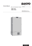
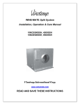
Dimensions
(6480m)
33,4' (TraY)
-
'E:::r
-
e
-0
I
I'
II
II
,I
II
II
J
~===t====
,
~~~~~~
-----
.,
';:
'I
II
II
II
II
m
~
t:
EO
:~
------:-3"
'"InOJ
"'-
Top
(33m.)
(1076mm)
A2,4"
(4Smo)
1,8' _
1 3'_
(21 mm)
(101000)
3S,8'
(670 •• )
O. S'
(810mm)
34 3'
(795m m)
31 .3"
(sao •• )
34.3'
23. S'
(Smm
5mtn}
o. '
0,2'
1\
+
~
t
f
1
J
i _________ ~
f-----------~
t
E,
E,
"'-
:
="Ii
I
I
1
o
.
0",
In"'~
:
1!11
e-
E'".
o
e,
e'"
o·
"'In
"""
"'.-
.~" __________
•
JI
~lL
E,
eO)
o
.
"''''
3L
Front
Po ..... er
{Main
supply
body
Side
cord
back}
exit
posl1lor.
(I05mm)
4
I'
Cooling unit parts
MDF-U76VA
Item
Specifications
H side
L side
KS240J1NS-7A
7FB-0-M101-011-06
KS370J1 NS-7A
7FB-0-M101-001-06
Compressor
Type
Code
Rating
Refrigerant oil
Cooling system
Starting relay
Overload relay
Starting capacitor
Running capacitor
Condenser
Type
Condenser
Pre-condenser
Frame pipe
Evaporator
Type
Accumulator
Capillary
Resistance
PSI· kg/cm 2
Length
Outer diameter
Inner diameter
Refrigerant
Dryer
Condensing fan
Condensing fan
motor
Thermostat, etc
Heater
Oil separator
220V, 60Hz
Ze-NIUS L22SA, Charged q'ty 850cc
Forced air cooling (partially) and oil cooler
AMVL-300TA
AMVL-300A
MRA999549201
1601JF/250VAC x 2
1601JF/250VAC x 2
151JF/400VAC
251JF/400VAC
Cascade condenser
Fin and tube
Coil pipe </l6.35
12 columns x 4 lines, P6.35mm
----Fin 88pcs
----W350mm
----</l6.35
Cascade condenser
Tube on sheet </l9.52
----Shell and tube </l80
----</l38
Ex. capillary
78PSI
0.37Mpa
34PSI
3000mm
</l2.4mm
</l1.2mm
3000mm
<!l2.0mm
</l0.9mm
500mm
<!l2.4mm
<!l1.2mm
R-404A, Charged q'ty 540g
n-Pentane (4wt%) 22.5g (36cc)
R-508S, Charged q'ty 370g
n-Pentane (12.4%wt) 52.4g (83cc)
3AXH-9, Char!]ed q'ty 18!]
Material: ASS, 4 blades, </l230mm
SV4-11AS5P
runnin!] capacitor: 1.01JF
Thermistor, 502AT
4AXH-6, Char!]ed q'ty 58!]
-----
-----
---------
PT1000n
Capillary heater, 12W x 2P
Ze-NiUS L22A: 445cc (384.8g)
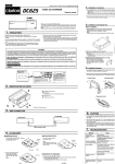
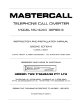
Refrigeration circuit
1111111111111
111111111111
H Ish temp, -;pLow temp,
-»
HIGH STAGE.
SIDE COMPRESSOR
-;p-
-;p-
PRE-CONDENSER
<E-
Ii.I
FRAME PIPE
I
Ii.I
'"w
~
~
d
ffi
W
t
"''"
f
CASCADE
CONDENSER
w
>:
=>
"*""
t
<E-
I
YJ
--7>
'-'
~
~
CONDENSER
"*""
:i
"'
(D
C>
'"
PRE-CONDENSER
~/\/\/\.r-----'
I
SUCTION
HEAT
EXCHANGER
«0-
Ii.
YJ
OIL
SEPARATOR
~ ~15~Wc~~2~sSOR
--7>
CAPILLARY
TUBE (L EX)
~
--7>
CAPILLARY TUBEIL)
HEAT EXCHANGER
EXPANS ION TANK
nnnPlntc:::
on PCB
CN8
CNll
#1-#2: Battery
#1-#3: Temp. sensor
CNl
CN7
#1-#2: Door switch
#5-#6: AT sensor
#7-#8: Filter sensor
#9-#10: Cascade sensor
#1-#3:Switching
power supply
o
CN2
MTR-480C(option)
CN9
#1-#2: H. Camp relay
CN6
Display PCB
CN4
#1-#2:Temp. control
relay
#3-#4: Heater relay
CN5
#1-#5: Switch PCB
~~~::2=rJ~~!::~::~o1~
1F
0
o
CN3
Remote alarm terminal
#l:COM.
#2: N.D.
#3:N.C.
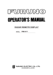
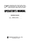
Connections on PCB
Connections on Temp controller PCB
Connector
Connects to
Usage
CN1
#1, #3: Switching power supply
To supply the power to PCB.
CN2
Network interface
To connect to MTR-4S0/L03 (option)
Remote alarm terminal
Remote alarm contact outputs.
#1: COM.
CN3
In normal condition, open for #1-#2 and closed
#2: N.O.
for #1-#3.
#3: N.C.
#1-#2: Temp. control relay
To control internal temperature (12VDC)
#3-#4: Heater relay
To supply the power to capitube heater (12VDC)
#1-#5: Switch PCB
To connect to each switch
#6-#7: Buzzer PCB
To connect to buzzer PCB
Display PCB
To connect to each LED
CN4
CN5
CN6
To detect door ajar
#1-#2: Door switch
To detect the ambient temperature
#5-#6: AT sensor
CN7
To detect the temperature in condenser outlet
#7-#S: Filter sensor
pipe.
#9-#10: Cascade sensor
To detect the temperature in cascade.
#1-#2: Battery(#1 :6V #2:Battery switch)
To supply the power during power failure
CNS
#3-#4:Transformer
CN9
#1-#2: H. Compo relay
CN10
Unused
CN11
#1-#3: Temp. sensor
To control compressor H ON/OFF (12VDC)
To detect the internal temperature.
III
Electrical Parts
MDF-U76VA
Compressor (H)
Compressor (L)
Starting relay (H)
Starting relay (L)
Overload relay (H), (L)
Electrolytic capacitor (H)
Electrolytic capacitor (L)
Running capacitor (H)
Running capacitor (L)
Condensing fan motor
Capitube heater
H Compo relay
Heater relay
Switching power supply
Power supply switch
Temp. sensor
AT sensor
Filter sensor
Cascade sensor
Battery switch
Battery
Step-up transformer
AC115V,60Hz
KS240J1NS-7A
Type
Code
7FB-0-M101-011-06
Rated voltage (50/60Hz)
220V, 60Hz
Winding resistance C-S(Aux)
1.7811
C-R(Main)
4.3411
KS370J1NS-7A
Type
7FB-0-M101-001-06
Code
Rated voltage (50/60Hz)
220V,60Hz
Winding resistance C-S(Aux)
1.6411
C-R(Main)
3.3511
AMVL-300TA
Type
Rating
AC300V
AMVL-300A
Type
Rating
AC300V
Type
MRA999549201
Rating
29.5A
250VAC, 160.u F
Rating
250VAC, 160.u F
Rating
Rating
400VAC, 15.u F
Rating
400VAC, 25.u F
SV4-11AA5P
Type
220-240V
Rating
Rating
230V, 11.2W
Type
AJM5211F
Contact capacity
20A
Type
G2R-1A-T
10A,250VAC
Contact capacity
Type
ZWS10-12/J
DC12V, 0.9A (TDK)
Rated output
1R11AZE201 R
Type
Rating 20A, 250VAC. Breaker SW
Type
THC-663
Rating
100011
Type
502AT
Rating
5KI1,25"C
502AT
Type
Rating
5KI1,25"C
502AT
Type
Rating
5KI1,25"C
SLE6A2-5
Type
Rating
250VAC,4A
Type
5HR-AAC
Rating
6V,1100mAH
Type
E168-3000
Rating S115V, P225V, 13.3A, 3000VA
20A
Fuse
cations of sensor
The following shows the temperature in thermal sensor (502AT-1) and its resistance value.
Temperature Resistance Temperature Resistance Temperature Resistance Temperature
ee)
(kQ)
ee)
(kQ)
ee)
(kQ)
ee)
Resistance
(kQ)
-50
154.5
-36
71.80
-22
35.65
0
13.29
-49
145.9
-35
68.15
-21
33.99
5
10.80
-48
137.8
-34
64.71
-20
32.43
10
8.84
-47
130.2
-33
61.48
-19
30.92
15
7.20
-46
123.1
-32
58.43
-18
29.50
20
6.01
-45
116.5
-31
55.55
-17
28.14
25
5.00
-44
110.2
-30
52.84
-16
26.87
30
4.17
-43
104.4
-29
50.23
-15
25.65
35
3.50
-42
98.87
-28
47.77
-14
24.51
40
2.96
-41
93.70
-27
45.45
-13
23.42
45
2.51
-40
88.85
-26
43.26
-12
22.39
50
2.13
-39
84.18
-25
41.19
-11
21.41
55
1.82
-38
79.80
-24
39.24
-10
20.48
60
1.56
-37
75.67
-23
37.39
-5
16.43
65
1.35
The following shows the temperature in thermal sensor (PT1 0000) and its resistance value.
Temperature Resistance Temperature Resistance Temperature Resistance
(Oe)
(kQ)
ee)
(kQ)
ee)
(kQ)
-140
450.83
-70
729.99
0
1000.0
-130
491.47
-60
769.02
10
1038.0
-120
531.83
-50
807.87
20
1076.0
-110
571.92
-40
846.58
30
1113.8
-100
611.76
-30
885.13
40
1151.4
-90
651.38
-20
923.55
50
1189.0
-80
690.78
-10
961.84
60
1226.4
'-J
..,.,
(J\
IT
c:::J~
eNG
eN2
I
-I>-
<
J>
rltl
BK
rtl.
l4J
MTR-L03
'"0
-I>-I>>-'
C
--,J
BATTERY
MTR-480
3:(J\
t:J I
..,.,
[
---
[OPTION
ttl
I
TERMINAL
~
::::l.
::J
L.
~
jfi'!J
IN.
(0
BK
BL
R
~
3P
BATTERY
SWITCH
Cal
eNs
(0
"'I
>-'
I
al
\Jl
-0
I
0
0
J>
:1 l.b.!!L. 1 13
[
0
~
I---l
10
I---l
Z
Q
BL
o
BL
-;:Jj
I -..:;: I
DOOR SWITCH
I---l
L.BL
J>
Q
L.BL
CAPITUBE HEATER
10
L,BL
J>
STARTING, CAP.L'
STARTING CAP.L
:s:
il:'
/
CONDENSING
R
F'ANMOTOR
CAPITUBE
FM
HEATER
S
~
,
Cl
V
"oioiH-,,""I'L--
'~;:g
PK CAPITUBE ~
''if
BR
r
tD
r
SENSOR
VI
:t:!;l
bf=~
~
x~
00
r
,..,
~
5k;
5t
GNIY
1"1~
~
~
-
!il"
Pl
~
~
@ ©-=-1"'1
r C'l '::t'l
~~ ~ <:::
("1
~Cl
:r"
Pl
:to
"
:t:
"
"
HOLDER
V
~;:gr-
IlK
'"
c~
~
~~
r
PO'w'ER
TRANS
..... f1,;I
it v
HARNESS H
HA
H
~
L
:~ ~ ~S'HITCH I~~
r=J91 ttf, . _.=_..
IlK ....
"'tI
HARNESS P
g
...........
BK
REMOTE
YL3
ALARM,
('yI
TERMINAL BATTERY ~
OPTION
MTR-480
~
@~
FUSE
(VI)
~
'"
~~RNESS
R
YL4P
-<
" "
~E
-<
Z
(t)
~ ~
BL
.,r
~
BK
(11""1
~3:
>n
~
'" <
L,"O
EARTH
S
~r;!
(,1:;::
:J
@
","0
DTDR
COMPRESSOR H
GN/Y
I~
BK
n'"
BK
S
y
'II
TERMINAL
~~
HEATER
READ WIRE ASSY rAN
FILTER
, ~lJ ~
HARNESS PN
BK
Gl
AT
(';;"
SENSOR
r
;,
r
Y BLR
.1ll:..
~8
... D
~;o
sM4P(W')
~
BL
HARNESS DPHD
I
~
: EC
(- HARNESS EC
rJI
HARNESS CH
HARNESS P
I
I
PK
PK
~
GNlYi
I~TH
1
III
'PK
I
EARTH
1III I
I
I
BK BK BK
2
3
5
-4
6
T]VVV[Vl
PK BR BK BK BR BK
III •
FR'tNE
TT
LBL
7
8
10
11 ,12
:0
IVVVVI
I
CN12
~
....
,!8 .........
~-~
'-
Cltdb:lt:d
:;u;:orr
~~fl~
,,"""
10,,0...(
"0
'"
~
~
~
I.
~
1L
vi BK
L.BLI
eN·
L-
1:1
STARTING'
BK
RELAY L
o
BK
STARTING
RELAY H
ili.cb.
...
2D-
<;;
<
~
::O;:o
7\~-<
r
;,
r«-<
.................
r<:(..-(
......... :::J:,..,
G'lo ... '
:cr-lr"
-If'TI"lC
",'"
~
<:
1
Y~
"...
"'"
"'"
"O~
r~
"
n"
~~
f-*
"
rz
nc
".z
"OZ
'"
eN'
o
CN13
0
t::Jz·;r:. ;r,.
'"
I:[~
:0
;Ilj-
1
01
::O"l]CC'I
fTl ....
[
~
2
3
FANMOTrlR
CAP,
III
I
m
BK
:t:
r-1.r.1
I~I~I~~
I~
W LBL LBL L.BL LBL
NESS H
I
eN
L.BL LBL L,BL
9
,.
LBL
Y R BL
eN
Iv
~
1:C~
N
IY
k
~Ni
Ii"
I....BL
e1
S:W'ITCHING EARTH
3[[: I:NI
lii=l'
CNS
POWER
SUPPLY
20
'"
n"
"
~:;!
"
.,," ""z
:-o-a:
!J:~ :t::z
'"
'"
""~
:0"
:t:
z
nC
1t
1
..J:I>
IBK IR
BATTERY
: HS
.
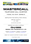
111111111111111
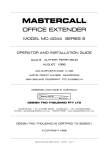
Circuit diagram
111111111111111
;~
ui
~
i
",'-'1.-.1
...
-
~
~
~
l 0~
~
..::.:, ~,
,:::::~,ya
~
t:~.
~
~
<
.
~
...
0...
I'JU
:
h
i~~ '~
;
:l'ff'1 DC +12V
.Rl.4
"
*E *0: 0:~
t;:
~
..'-'"
~
!~
!~~~
0g
O.Ol"~ L_1'I1.;-z--]
0,01.1"
,
. ~.
Ir
,---
."'~
.m.,.L
~~
~
~
'"'~
CONOI TlON
.~. ,-1.0-
BUZZER
""~
I~
,--1
I
[)(>
""...Lo--
~-u
SET
0-
ALAR\,{ TEST
:
,I
:
:,
1'3.8
,
P3.5
1'3 ••
"
"""'"
•• m••
~.
I:::
.
I
,,}-
,. .. -- -- -- - --- _______ ,
!S28£~~~~-s
: .
~i
1m
,
:
f\
i
0
£8Z0!!UC-,V:
o
0
L---SOZZe-fn·wif----J
.?
~ tl'IO~2UHl
•.. ~11
"o,-.!.+.r--h-1r-rrH-+1'-H:'i ,
'" '"''
"'"
~ ~;¥~;~;;~;t
1
~wP1
1'2.0
If: ~
1'2.1
'"''
P2.2
"';;::'
Pl!.7
,
,
1
JJIJ
•
to
It lli'-~ lli~ I- I" Ii0
2
~
u
0
J
2
0
<
J
<
c;
oc
~.
z
0
~
~
~
W
~
~
~
~
0
0
0
W
..,
~
~
~
0
u
DISPLA.Y PWB
I
I
'"
,I
!ila~5
"'0-"'0-
~
0
0
0
~
e
~
0
g
~
H
""
1
1111111
IIIIIII
1.
Control specifications
Key and Switch
BUZZER
In alarm condition, audible alarm will silence when this key is pressed, but
remote alarm will be still active and message will not be eliminated.
When a power failure is occurred (during battery back-up), press this key to call
a chamber temperature display for 5 seconds.
ALARM TEST
When this key is pressed, unit will step to Alarm Test mode and ALARM lamp
will blink, audible alarm will sound intermittently, digital LED display will go off
and remote alarm will be activate.
A chamber temperature display will appear after approx. 90seconds elapse.
(Auto return)
If Alarm Test is performed when a battery switch is in off position, "E09" will
flash.
SET
Press this key to step to setting mode and the 2"' digit in LED display will blink.
Press this key again to memorize a value. Also used to decide and memorize
value in each function and setting mode.
STATUS
Press this key during STATUS lamp is on to display occurring status code
("--1", "--2", "--3"). Unused when STATUS lamp is off.
In setting mode, press this key to move curser among 1" digit - 3'" digit.
If this key is pressed for 5 seconds when a chamber temperature is displayed,
"L_O" will be displayed and go into key lock setting mode.
~
(Digit shift key)
It]
(Numerical value
shift key)
2.
In setting mode, press this key to add numerical value in a displayed digit.
If this key is pressed for 5 seconds when a chamber temperature is displayed,
"FOO" will be displayed and go into function mode. (use this key and digit shift
key to input function code and press SET key to go into each function mode)
Temperature control
Setting range
Display range
How to set
temperature
Unacceptable setting
value
3.
4.
IIIIIII
Key Lock mode
Setting range
How to set Key lock:
Function mode
Setting range
Display range
-50°C--90°C
-180-50
Press SET key to step to setting mode and change a value by using It] key
and ~key.
Press SET key to store the value in non-volatile memory.
If a value which deviates from setting range is input and SET key is pressed,
error sound come out and keep setting mode.
°
(Release), 1 (Lock)
In a chamber temperature display, press ~ key for 5 seconds to step to
Key Lock mode. ("L_O" or "L_1" is displayed. Factory default display: L_O)
Change a blinking digit to "0" or "1" by using It] key.
How to set Function
mode:
00-50
00-59
00, 16 and 33-43, 44-49, 51-59 are unused.
In chamber temperature display, press It] key for 5 seconds to step to
function mode and "FOO" is displayed.
Change a value by using It] key and ~ key.
Press SET key to go into each function mode. If "00" or "16" is input and
press SET key, return to chamber temperature display.
Unacceptable setting
value:
f a value which deviates from setting range is input and SET key is pressed,
error sound come out and keep setting mode.
5.
Error codes
E01:
E02:
E03:
E04:
E05:
E06:
EO?:
E08:
E09:
E10:
Temp. sensor is open circuited
Temp. sensor is short circuited
Cascade sensor is open circuited
Cascade sensor is short circuited
Filter sensor is open circuited
Filter sensor is short circuited
AT sensor is open circuited
AT sensor is short circuited
Battery switch is in off position or battery is unconnected
Compressor temperature is abnormal
(1) Temp. sensor
Open circuit (E01):
Short circuit (E02):
(2) Cascade sensor
Open circuit (E03):
Short circuit (E04):
(3) Filter sensor
Open circuit (E05):
Short circuit (E06):
(4) AT sensor
Open circuit (EO?):
Short circuit(E08):
If a temp. sensor temperature is higher than 50°C, E01 and "50" will be
displayed alternately, audible alarm will sound intermittently and remote
alarm contact will be active.
Compressor will be kept running.
Press BUZZER key to silence audible alarm.
If a temp. sensor temperature is lower than -1?0°C, E02 and "-1?0"- "-180"
will be displayed alternately, audible alarm will sound intermittently and
remote alarm contact will be active.
Compressor will be kept running.
Press BUZZER key to silence audible alarm.
If a cascade sensor temperature is lower than -65°C, E03 and chamber
temperature will be displayed alternately, audible alarm will sound
intermittently and remote alarm contact will be active.
Both High and Low side compressors will be forced to turn off.
Press BUZZER key to silence audible alarm.
If a cascade sensor temperature is higher than 60°C, E04 and chamber
temperature will be displayed alternately, audible alarm will sound
intermittently and remote alarm contact will be active.
Both High and Low stage side compressors will be forced to turn off.
Press BUZZER key to silence audible alarm.
If a filter sensor temperature is lower than -60°C, E05 and chamber
temperature will be displayed alternately, audible alarm will sound
intermittently and remote alarm contact will be active.
High stage side compressor will be forced to turn off.
Press BUZZER key to silence audible alarm.
If a filter sensor temperature is higher than 130°C, E06 and chamber
temperature will be displayed alternately, audible alarm will sound
intermittently and remote alarm contact will be active.
Press BUZZER key to silence audible alarm.
If an AT sensor temperature is lower than -60°C, EO? and chamber
temperature will be displayed alternately, audible alarm will sound
intermittently and remote alarm contact will be active.
Regardless of ambient temperature, operate warm up starting of L side
compressor when AT sensor error is happened.
Press BUZZER key to silence audible alarm.
If an AT sensor temperature is higher than 60°C, E08 and chamber
temperature will be displayed alternately, audible alarm will sound
intermittently and remote alarm contact will be active.
Regardless of ambient temperature, operate warm up starting of L side
compressor when AT sensor error is happened.
Press BUZZER key to silence audible alarm.
(5) Battery SW is off
position or battery
is unconnected(E09):
If ALARM TEST key is pressed when battery switch is off position or battery
is unconnected, E09 will be displayed.
(6) Compressor
abnormal
temperature (E1 0):
If a filter sensor temperature is higher than 54°C, it regards as fan motor
failure or abnormal compressor temperature.
E10 and chamber temperature will be displayed alternately and high stage
side compressor will be forced to turn off.
Press BUZZER key to silence audible alarm.
If a value which is obtained from filter sensor temperature subtracts an
ambient temperature is equal or lower than 10°C, compressor will turn on.
(7) Error code priority
No.1:
No.2:
No.3:
No.4:
No.5:
6.
Warning function
High temperature
alarm:
Cascade sensor error (E03, E04) ... Compressor is forced to turn off
Filter sensor error (E05, E06) ... Compressor protection is uncontrollable
Abnormal compressor temp.(E10) ... Compressor temporary turns off
Temp. sensor error (E01, E02) ... Compressor is forced to turn on
AT sensor error (E07, E08) ... Warming-up is forced to be performed in any
ambient temperature.
If a chamber temperature is equal or higher than set temperature + high
temp. alarm set temperature +1°C, ALARM lamp and LED display will blink,
audible alarm will sound intermittently after 10 minutes of delay, and remote
alarm will be active.
If a chamber temperature is equal or lower than set temperature, ALARM
lamp will be off, LED display will blink, audible alarm will silence and remote
alarm will turn off.
Press BUZZER key is to silence audible alarm, but remote alarm will not be
inactive.
Low temp. alarm
If a chamber temperature is equal or lower than set temperature - low temp.
alarm set temperature _1°C, ALARM lamp and LED display will blink, audible
alarm will sound intermittently after 10 minutes delay, and remote alarm will
be active.
If a chamber temperature is equal or higher than set temperature, ALARM
lamp will be off, LED display will blink, audible alarm will silence and remote
alarm will turn off.
Press BUZZER key to silence audible alarm, but remote alarm will not be
inactive.
Door alarm
If an outer door is left open, DOOR lamp (DP54: red) will turn on. Audible
alarm will sound after 1-15 minutes (default: 2 minutes) of delay. Audible
alarm and remote alarm are not synchronized. Audible alarm will keep
silence by pressing BUZZER key (no ring back function).
Power failure alarm
If power supply switch is off or power interrupt during battery switch is in ON
position, it regards as power failure condition.
If a power failure condition keeps for 3 seconds, ALARM lamp will blink,
audible alarm will sound intermittently and remote alarm will be active.
If a power returns within 3 seconds, a unit will start operation at default
settings and remote alarm will be off.
Press BUZZER key to silence audible alarm, but remote alarm will not be
inactive. Remote alarm will keep active until chamber temperature is
stabilized after the power interruption.
Press BUZZER key during power failure condition to display chamber
temperature for about 5 seconds.
7.
Status function
When the unit become following 3 conditions, STATUS lamp (DP52: orange) turns on. Press STATUS
key during this condition to display each status code.
Status 1: When AT sensor temperature is lower than O'C or higher than 35'C, display "--1 ".
Status 2: Decrease power supply voltage (between TP7 and TP3: lower than CD2.01V), display
"__2",
Status 3: Running rate is over 95%, display "--3".
Display method
When more than one status is occurred at same time, press STATUS key to display status code in
following order.
" ___ " ---+ "--1" ~ "--2" ---+ "--3" -+ back to "--1"
If there is no status notice, previous status code is displayed (interval is about 3 seconds)
" ___ " ---+ "--1" --+ "--2" --+ "--2" --+ back to "--1"
(when status 1 and 2 are occurred, status 2 is displaying for about 6 seconds)
Return to chamber temperature display after about 90 seconds or all status is disappear.
8.
Running rate
Running rate = (ON time I (ON time + OFF time)) x 100%
Measurement of running rate:
It regards as 'cycle start' when a compressor turns on after it turned off once
chamber temperature was lower than set temperature.
Running rate should be measured on and after 2 hours then.
ON time (Min.) = Time until P3.1 in IC5 first reaches from LOW to HIGH
OFF time (Min.) = Time until P3.1 in IC5 reaches from HIGH to LOW
Condition to calculate running rate: 2 hours after cycle start
ON time(Min.)
OFF time(Min.)
Running rate
-0
-0
Impossible to. obtain
>0
-0
running rate by
calculation (=0%)
-0
>0
>0
>0
0-100%
Note) Running rate cannot be measured when a chamber temperature becomes higher than set
temperature + 4.0'C.
Please wait until a chamber temperature is stabilized.
Obtain for diagnosed value of overload running rate:
Step to F20 and input '000'.
Start to calculate
running rate
Start to diagnose running rate
Settemp.
Compressor OFF (1st)
Reach to set temp.
2 hours
8 hours stabilized
(Cycle run)
Diagnosis is done with every 8 hours
until chamber temp is higher than
Set temp + 4.0
Calculation for diagnosed running rate
=(-(Set temp.)XO.9)+((ATXO.9-4.5°C))-((Set temp.+85°C) 110))
Diagnosis of running status
If diagnosed value running rate is more than actual running rate, it diagnosed as 'Normal'
operation (DP52: off).
If diagnosed value running rate is equal or lower than actual running rate, it diagnosed as
'Overloaded' operation (DP52: on).
If it is impossible to obtain actual running rate (=222), it is impossible to diagnose status (DP52:
off).
Diagnosis will be done in every 8 hours.
9.
Other functions
Auto Return:
If there is no key operations for 90 seconds in setting mode, Key lock mode
and Function mode, return to chamber temperature display.
Note) Auto return does not work in FOg and F10.
Ring Back:
In alarming condition, audible alarm will sound again if someone presses
BUZZER key to silence audible alarm. This is to prevent that buzzer sound is
stopped by third person and the operator cannot notice buzzer.
Ring Back time can be set in F25.
Display of sensor
temperature:
F12: Display of temp. sensor temperature
(Ex. -80.2°C --> Displayed as '80.2')
F13: Display of cascade sensor temperature
(Ex. +6rC --> Displayed as '067')
F14: Display of filter sensor temperature
(Ex. +6rC --> Displayed as '067')
F15: Display of AT sensor temperature
(Ex. +6rC --> Displayed as '067')
Display of battery
accumulation time:
F03: Display of battery accumulation time
(Ex. 2years and 6months --> Displayed as '02.5')
BATTERY lamp (DP55: orange) will turn on when a display becomes
'02.8'.
<Reset of battery accumulation time>
Step to F06 and input '409'. Press SET key to reset accumulation time.
After reset, BATTERY lamp (DP55: orange) turn off.
Display of condensing
fan motor
accumulation time:
F32: Display of condensing fan motor accumulation time
(Ex. 5years and 8months --> Displayed as '05.8')
BATTERY lamp (DP55: orange) will blink when a display becomes
'05.6'.
<Reset of condensing fan motor accumulation time>
Step to F06 and input '410'. Press SET key to reset accumulation time.
After reset, BATTERY lamp (DP55: orange) stop blinking.
Forcible ON/OFF
operation in capillary
heater:
F18: If you input 'ODD', compressor will turn off and capillary heater will be
forcibly turned on.
If you input 'O~~' during capillary heater turns on, capillary heater will be
forcibly turned off.
If you input '001', capillary heater will be forcibly turned off.
Compressor will be turned off every 18hours, but capillary heater will
be kept turned off.
10,
Function mode
FOO
Unused: return to chamber temperature display
F01
Setting of high temperature alarm set temperature
F02
Setting of low temperature alarm set temperature
Display of battery accumulation time
F03
Setting of door alarm delay time
F04
F05
Setting of compressor delay time
F06
Setting of service code (Code: 384), Reset of accumulation time
F07 •
Temperature sensor zero calibration
F08 •
Cascade sensor zero calibration
F09 •
Compressor continuous running mode ... Factory use
F10 •
Program running mode ... Factory use
F11 •
PCB test mode ... Factory use
F12 •
Display of temp. sensor temperature
F13 •
Display of cascade sensor temperature
F14 •
Display of filter sensor temperature
F15 •
Display of AT sensor temperature
F16
Unused: return to chamber temperature display
F17 •
Setting/Display of model code (Initialization of non-volatile ROM and memory)
F18 •
ON/OFF control of capillary heater
F19 •
Setting of capillary heater ON time
F20 •
Setting of diagnosed value of overload running rate
Setting of communication 10
F21
F22
Setting of communication mode
F23 •
Display of power supply voltage
F24
Linkage between remote alarm and buzzer
F25
Setting of Ring Back time
F26 •
Display of actual operation rate
F27 •
Display of diagnosed value for overload running rate
F28 •
Display of delay time for measuring running rate (2 hrs timer)
F29 •
Display of delay time for measuring running rate (8 hrs timer)
F30 •
Display of ROM version
F31 •
Setting of filter alarm operation ON/OFF
F32
Display of condensing fan motor accumUlation time
F33-F43
Unused
F44 •
Adjustment of display of power supply voltage
F45-F49
Unused
F50
Setting of alarm delay time
F51-F59
Unused
•
Setting
procedure:
Input service code '384' in F06 prior to use function codes which are marked with "
To cancel service code, input "000" in F06 or turn the power off.
In chamber temperature display, press III key for 5 seconds to display "FOO".
Input Function code by pressing III key and ~ key.
Press SET key to go into each function mode.
FOO:
<Purpose>
<Operation>
No function to be set in order for user who enter by mistake to return.
Press SET key in "FOO" display to return to chamber temperature
display.
F01:
<Purpose> Setting of high temperature alarm set temperature
<Operation> Input F01 and press SET key to display "010" (Factory default).
Setting range is '005-040'.
Change a value by pressing III key and ~key.
Press SET key to store the value and to return to chamber temperature
display.
F02:
<Purpose>
<Operation>
Setting of low temperature alarm set temperature
Input F02 and press SET key to display "-10" (Factory default).
Setting range is "-05"-"-40".
Change a value by pressing III key and ~ key.
Press SET key to store the value and to return to chamber temperature
display.
F03:
<Purpose>
<Operation>
Display of battery accumulation time
Input F03 and press SET key to display F03 and accumulation time
("00.0" if battery used for 36days or less) alternately.
Press SET key to return to chamber temperature display.
F04:
<Purpose>
<Operation>
Setting of door alarm delay time
Input F04 and press SET key to display '002' (Factory default).
Setting range is '001 '-'015'. (Unit: Minute)
Change a value by pressing ~ key and ~ key.
Press SET key to store the vaJue and to return to chamber temperature
display.
F05:
<Purpose>
Setting of compressor delay time when a power is supplied (a power
returns from power failure).
<Operation> Input F05 and press SET key to display '003' (Factory default).
Setting range is '003'-'015'. (Unit: Minute)
Change a value by pressing ~ key and ~ key.
Press SET key to store the vaJue and to return to chamber temperature
display.
F06:
<Purpose> Setting of service code and reset of accumulation time
<Setting of service code>
Input F06 and press SET key to display '000' (Factory default).
Set service code to "384" by pressing III key and ~ key.
Press SET key to store the value and to return to chamber temperature
display.
<Reset of battery accumulation time>
Input service code '384' in F06.
Input '409' to reset battery accmulation time and to return to chamber
temperature display.
<Reset of condensing fan motor accumulation time>
Input service code '384' in F06.
Input '410' to reset fan motor accumulation time and to return to
chamber temperature display.
<Cancellation>
Input F06 again and press SET key to display '384'.
Change a value to '000' by pressing III key and ~ key.
Press SET key to store the value and to return to chamber temperature
display.
A display will be also changed to '000' if you turn a power off and on,
but it will not be stored in non-volatile memory.
Note) Service code '384' is stored in non-volatile memory during battery
back-up.
F07:
<Purpose> To match a temperature in temp. sensor with 1/2H air temperature
<Operation> Input service code in F06 prior to use this mode,
Input F07 and press SET key to display '00.0' (Factory default).
Setting range is '-4.9'-'04.9'.
Change a value by pressing III key and ~ key.
Press SET key to store the value and to return to chamber temperature
display.
F08:
<Purpose> To calibrate a temperature in cascade sensor
<Operation> Input service code in F06 prior to use this mode,
Input F08 and press SET key to display '00,0' (Factory default),
Setting range is '-9,9'-'09,9',
Change a value by pressing III key and ~ key,
Press SET key to store the value and to return to chamber temperature
display,
F12:
<Purpose> To display a temp, sensor temperature
<Operation> Input service code in F06 prior to use this mode
Input F12 and press SET key to display alternately F12 and "XXX'
(current chamber temperature), Press SET key to return to chamber
temperature display, 3 digits indication, Minus "-" is not indicated,
Ex) "-79,5°C" ---> Indicated as "79,5"
F13:
<Purpose> To display a cascade sensor temperature
<Operation> Input service code in F06 prior to use this mode
Input F13 and press SET key to display alternately F13 and "XXX'
(current temperature in cascade sensor), Press SET key to return to
chamber temperature display,
F14:
<Purpose> To display a filter sensor temperature
<Operation> Input service code in F06 prior to use this mode,
Input F14 and press SET key to display alternately F14 and "XX.X"
(current temperature in filter sensor), Press SET key to return to
chamber temperature display,
F15:
<Purpose> To display an AT sensor temperature
<Operation> Input service code in F06 prior to use this mode
Input F15 and press SET key to display alternately F15 and "XXX'
(current temperature in AT sensor), Press SET key to return to chamber
temperature display,
F17:
<Purpose> Change of model code and initialization of non-volatile memory
<Change of model code>
Service code should be input in F06 prior to use this mode,
Input F17 and press SET key to display 'OOX',
Change a value (001-009) by pressing III key and ~ key,
Press SET key to store and return to chamber temperature display,
F18:
<Purpose>
<Operation>
On/off control for capillary heater
Service code should be input in F06 prior to use this mode
Input F18 and Press SET key to display '000' (Factory default),
Change to alternative value '000' or '001' by press III key and ~ key,
Press SET key to store the value and return to chamber temperature
display,
000: Capillary heater will be forcibly turned on when it is turned off,
or Capillary heater will be forcibly turned off when it is turned on
001: Capillary heater will be inactive
F21:
<Purpose>
<Operation>
Setting of serial communication ID
Input F21 and press SET key to display '000' (Factory default),
Setting range is '001' - '255" by pressing III key and ~ key,
Press SET key to return to chamber temperature display,
F22:
<Purpose>
<Operation>
Setting of serial communication mode
Input F22 and press SET key to display '000' (Factory default)
Change a value by pressing ~ key and ~ key.
Press SET key to store the value and return to chamber temperature
display.
Control mode (the 3'd digit)
0: Local (initial)
1: Remote
Baud rate (the 2,d digit)
0: 2400bps (initial)
1: 4800bps
2: 9600bps
Note) Setting value will not be changed by operating control panel when
control mode is set in 'Remote'.
F23:
<Purpose> Display of power supply voltage (Unit: %)
<Operation> Service code should be input in F06 prior to use this mode.
Input F23 and press SET key to display alternately F23 with 'xxx'
(current power supply voltage).
Press SET key to return to chamber temperature display.
F24:
<Purpose>
<Operation>
Linkage between remote alarm and buzzer
Input F24 and Press SET key to display '000' (Factory default).
Change a value by pressing ~ key and ~ key.
Press SET key to store the value and return to chamber temperature
display.
000: Remote alarm does not link with buzzer
001: Remote alarm links with buzzer
F25:
<Purpose>
<Operation>
Setting of Ring Back time
Input F25 and press SET key to display "030" (Factory default).
Setting range is '000'-'060'.
Change a value by pressing III key and ~key.
Press SET key to store the value and to return to chamber temperature
display.
000: Not Ring Back
010: 10 minutes
020: 20 minutes
030: 30 minutes
040: 40 minutes
050: 50 minutes
060: 60 minutes
F26:
<Purpose>
<Operation>
Display of running rate (Unit: %)
Service code should be input in F06 prior to use this mode.
Input F26 and press SET key to display alternately F26 with "XXX"
(Current running rate).
Press SET key to return to chamber temperature display.
F27:
<Purpose>
<Operation>
Display of diagnosed value for overload running rate
Service code should be input in F06 prior to use this mode
Input F27 and press SET key to display alternately F27 with "XXX"
(current diagnosed value for overload running rate).
'000' will be displayed until accumulation time for 8H timer becomes 480
minutes.
Factory default is '095' (fixed value), excepting diagnosed value which
is obtained from calculation in F20.
Press SET key to return to chamber temperature display.
F28:
F29:
<Purpose>
Display of delay time to start measuring running rate
(2hrs timer; 000-120 min)
<Operation> Service code should be input in F06 prior to use this mode
Input F28 and press SET key to display alternately F28 with 'xxx'
(current count value for delay time to start measuring running rate).
Press SET key to return to chamber temperature display.
When a displayed value becomes '120', unit will start measuring
running rate.
<Purpose>
<Operation>
Display of delay time to start diagnosing running rate
(8hrs timer; 000-480 min)
Service code should be input in F06 prior to use this mode.
Input F29 and press SET key to display alternately F29 with 'xxx'
(present count value for delay time to start diagnosing running rate).
Press SET key to return to chamber temperature display.
8hours timer start counting after 2hours timer expires.
When a delay time becomes '480', unit will start diagnosing running
rate.
F30:
<Purpose>
<Operation>
ROM version is displayed
Service code should be input in F06 prior to yse this mode.
Input F30 and press SET key to display alternately F30 with "XJ<X"
(Ver.1.00 -> "1.00").
Press SET key to return to chamber temperature display.
F31:
<Purpose>
<Operation>
Setting of audible alarm when filter alarm is occurred
Input F31 and press SET key to display "001" (Factory default).
Change to alternative value '000' or '001' by pressing III key and~key.
Press SET key to revert to chamber temperature display.
000: Audible alarm is turned off
001: Audible alarm is turned on
F32:
<Purpose> Display of accumulation time of condensing fan motor
<Operation> Input F32 and press SET key to display F32 and accumUlation time
("00.0" if battery used for 36days or less) alternately.
Press SET key to return to chamber temperature display.
F44:
<Purpose> Adjustment for difference between display and actual power source
<Operation> Input F44 and press SET key to display '000' (Factory default).
Setting range is '000'-'003'.
Press SET key to return to chamber temperature display.
Setting value
000
001
002
003
F50:
<Purpose>
<Operation>
Unit status
0% (Not changed)
3% added to displayed value
5% added to displayed value
7% added to displayed value
Setting of alarm delay time
Input F50 and press SET key to display '015' (Factory default).
Setting range is '000'-'015'.
Change a value by pressing III key and ~ key.
Press SET key to store the value and to return to chamber temperature
display.
11.
L side compressor operating condition
Condition of warm up starting operation
When L side compressor starts in low ambient temperature, unit gives short time voltage
application repeatedly to warm up L side compressor. This is for ensuring startability and operates
required number of times based on ambient temperature condition.
To ensure startability, required number of times is different based on ambient temperature
condition (refer to following list). However, this operation is for areas (used voltage: 100V/115V).
So, this operation is not done for areas (used voltage: 220-240V) and L side compressor start
normally.
Model code
001/002/004
/OOS
010
003/006/007
/008/009
Ambient temperature
('C)(F1S)
Less than S'C
S'C-1S'C
1S'C-2S'C
More than 2S'C
Sensor open/short circuit
Number of short time
voltage application
14
9
Less than S'C
14
9
S'C-10'C
More than 10'C
Sensor open/short circuit
6
No warm up
9
No warm up
Starting
Operation
21 sec ON
3 min OFF
9 sec ON
3 min OFF
9
No ;yarm up operation
Count of L side compressor off period
If L side compressor is stopped for a long time in low ambient temperature condition (by changing
set value, power failure, etc), it incurs low startability. Therefore, it counts its off period and if it
stops more than 120 minutes, operates warm up for L side compressor re-start. Off period counting
starts from L side compressor stop or power failure alarm occurs.
Note) Off period counting operates when the unit power supply is ON or battery switch is ON and
micro computer is operating during power failure. Therefore, counting does not work when the unit
power supply is OFF or power supply returns before power failure alarm is on after micro computer
reset by power failure.
Warm up operation after reset
When chamber temperature is equal or less than set temperature + 10'C, unit regards as instant or
short time power failure and does not operates warm up (regard L side compressor as warm
enough).
However, chamber temperature here is not filtered data for display (TEMPO.PV), use raw data of
PT sensor resistance (TEMPO.PVFIL).
In this case, move to cycle condition immediately and L side compressor start running when it
fulfills one of following conditions after one minute from H side compressor running after delayed
time.
1. Cascade temperature is less thim -34'C
2. Pass 3 minutes (cycle running) or 15 minutes (initial start) after H side compressor running.
12.
Timing chart of L side compressor starting operation
Operate L side compressor starting based on following timing.
1. Apply power supply
2. H compo is on after finishing compo delay time.
3. If H side compressor is running more than 3 minutes and cascade sensor temperature become
equal or less than -34°C, H side compressor is OFF. (If H side compressor is running more than
15 minutes, H side compressor is also OFF)
4. L side compressor starts 10 seconds after H side compressor is OFF.
5. L side compressor is OFF after 20 seconds of L side compressor running. After passing 3
minutes, start again.
6. After repeating No.5 operation required times based on ambient temperature, turn H side
compressor ON again, then move to normal operation of L side compressor.
10sec
=;tIC=>
II
more than
1min
II 9sec
:H
~
morethan
3min
II
:
I
I
:<===0>;1 :
:
ON
Power supply
OFF
H compo operation
ON
OP6: turn on
OFF
L compo operation
ON
DP2
OFF
I I
1. Apply power supply 2. H compo ON
3. H compo OFF
4. LCOJ.t
I
5. L compo OFF
or
Passed 15 min after
H compo is ON.
6. H
compo
ON
ON
4. L compo ON
1 min after H compo
is ON and cascade
sensor temp. is less
than _34 DC.
6. L compo
normal operation
4. Lcomp. ON
5. L compo OFF
5. L compo OFF
1 min after H compo
is ON and cascade
sensor temp. is
less than _34 DC.
or
Passed 3 min after
H compo is ON.
13.
Compressor control (differential) value
Compressor H:
Turns on when a chamber temperature is set temperature -O.4'C.
Compressor H. L:
Turns off when a chamber temperature is set temperature -1.3'C
Compressor L:
1) Turns on when compressor H turns on and a temperature in cascade sensor is -34'C.
2) Turns on after 3 minutes (15 minutes in initial response) since compressor H was turned on
Interval:
It takes 1 minute until one compressor turns on after another one was turned off.
Note) Compressor L does not turn on until 1 minute after compressor H turned on, if a temperature
in cascade sensor is lower than -34'C. Compressor L does not also turn on for 1 minute after
compressor H turn on even if temperature in cascade sensor is lower than -34'C.
Chamber temp.
Set temp. -O.4<>C
Chamber temp.
Over I min
=
Chamber temp.
Set temp. -OAoe
=
Over Imin
Comp.delaytime
= Set temp. -I.
Set temp.
Set temp. -OAoC
. . . . .:'f-r_
Settemp. _1.4°C
------------1'~
Cascade Temp.
=-34°C
ON
OFF
ON
OFF
Compressor H protection:
Compressor H turns off to prevent it from being warmed up that is caused by fan motor locked.
Filter sensor tem perature:
Compressor H turns off when a temperature in filter sensor is higher than 56'C. It will turn on again
when the filter sensor temperature is lower than ambient temperature +10'C.
14.
Delay time
Compressor delay time (Factory default: 3 minutes)
When a compressor H/L is turned off after applying power or during cycle operation, it has a delay
time to start the compressor again. Delay time can be set in F05.
Temperature alarm delay time (Factory default: 10 minutes)
When high or low temperature alarm is triggered, audible alarm and remote alarm are active after
delay time. (alarm lamp and display are immediately blink) Delay time can be set in F01/F02.
Door alarm delay time (Factory default: 2 minutes)
When outer door is kept opened, audible alarm will be active after delay time. Delay time can be set
in F04.
Power failure alarm delay time (about 3 seconds fixed)
When a power is interrupted, power failure alarm will be occurred after about 3 seconds of delay
time. Delay time cannot be changed.
15.
Preventive action for oil logging in capillary
Purpose:
To prevent oil logging in capillary, capillary heater will be active by turning both compressor Hand
L off by regularly period.
Operation:
Both High and Low side compressor will be forcibly turned off and a capillary heater relay (CN4:
3-4) will be active. DP3 (red lamp) will turn on.
Frequency:
8 minutes in every 18 hours (Setting time can be set in F19)
Timing to start operation:
Operation is ordered after 18 hours of unit running (every 18 hours afterwards).
1. 9 seconds after both compressor Hand L are turned off during cycle operation.
2. If the compressor is kept running for more than 60 minutes after operation is ordered,
compressor is forcibly turned off and start operation.
Control of capillarv heater:
Capillary heater will be forcibly turned on or off in F18.
16.
Sensor offset
Offset value:
(1) Temperature sensor: +1.3°C (Changeable in FO?)
(2) Cascade sensor: +/-O.O°C (Changeable in F08)
(3) Filter sensor: +/-O.O°C
(4) AT sensor: +/-O.O°C
17.
Remote alarm terminal
Operation:
When an alarm is occurred, remote alarm contact (RLY2) switches the position.
Normal
In alarm
18.
CN3
1 - 2 (N.O.) 1 - 3 (N.C.)
Open
Close
Close
Open
Operation and setting after a power is reset
Settinqs when a power is supplied (Power on resell
Alarms: OFF
Compressors: OFF
Remote alarm: OFF
Ring Back: 30 minutes
Door alarm delay time: 2 minutes
Timers: Reset
2H timer, 8H timer: 0 (Reset)
Warm up starting: ON
Counting of compressor L OFF period: Reset
Setting data: Read by non-volatile memory
Momentarv power failure:
When a chamber temperature is lower than set temperature+1 DoC, unit will determine as
'Momentary power failure' is occurred.
Settings after unit returns from power failure:
Alarms: OFF
Compressors: OFF
Remote alarm: ON
Door alarm delay time: 2 minutes
Timers: Reset
2H timer, 8H timer: 0 (Reset)
Warm up starting: OFF
Counting of compressor L OFF period: Reset
Setting data: Read by non-volatile memory
19.
Lamp and display
Lamp operation:
<Display PCB>
DP51:
DP52:
DP53:
DP54:
DP55:
DP56:
Red lamp: ALARM
In alarm conditions: blink
Green lamp: STATUS
In STATUS mode: turn on
Orange lamp: FILTER
In filter alarm: turn on
Red lamp: DOOR
When door is opening: turn on
Orange lamp: BATTERY
When battery accumulation time becomes 2.8 years: turn on
When fan motor accumulation time becomes 5.6 years: blink
Lock (Unused)
<Control PCB>
DP1:
DP2:
DP3:
DP4:
DP6:
Orange lamp
Turn on: no alarm
Turn off: High/low temp. alarm (15min. delay), sensor error,
power failure
Green lamp
Turn on: L side compressor is ON
Turn off: L side compressor is OFF
Red lamp
Turn on: Capillary heater is ON
Turn off: Capillary heater is OFF
Yellow lamp (Unused)
Green lamp
Turn on: H side compressor is ON
Turn off: H side compressor is OFF
Examples of display:
Chamber temp.
-79.5°C
Decimal point of chamber temp. -80.0
CJLJI
Set tem p.
-80. DoC
Function
F03
:- U ::JI
Operation monitoring
LCP
Service code
384
-.J I I I_II
-.J CJ
I.
Error
E01
Set value
004
Key Lock
Buzzer tone:
1. Alarms
2. Key operation
3. Set value memory
4. Out of settable range
5. Door alarm
Sensor offset
Accumulation time
-5.0
8H timer 135
ILl 101
Intermittent tone
Click tone
Click tone
Continuous tone (1 second)
Intermittent tone (interval is shorter than No.1)
I: Ipl
el::I:1
:Hhl
111111111
Parts layout
111111111
<Lower left side>
r.n,ntrnl panel
Step-up transformer
<Lower back side>
..J~
/
Door latch
Handle
H/L side compressor
<Lower front side>
Expansion
AT sensor
Filter
Battery switch
Power s,,"tCrL_ _
Temp. control PCB
12P terrnim3l---
W-- - - Power transformer
Starting
Switching power supply
ca~lacitor1 U2:!!I""_ _-=::=r-~!!!
Running capatiror H
Starting capaCitor H
'Following data are the reference only, so they do not assure product's performance.
MDF-U76VA Pull-down Temperature AT30°C, 115V60Hz
40
~
20
\
~
P
...
...'"
Co
...."::l
"E
f"
1\
0
~
\
-20
-40
1\
~
-60
-80
~ I'--.
-100
o
2
3! 4
5
6
7
8
9
10
11
12
13
14
15
Time [h]
MDF-U76VA Pull-up Temperature AT30°C
o
-10
~-20
~
/"'
..." -30
.a
~ -40
"Co
./
f-
-60
/
-70
-90
V
/
~ -50
-80
----
V
--L.---
/
V
/
/
V
/
/
o
1
2
3
4
5
6
Time [h]
7
8
9
10
11
12
MDF-U76VA H/L EVA Temperature AT30°C, 115V60Hz
40
20
f\\
;'
'---\
0
~
~
Q)
'-
"til'- -40
Q)
f-
'"
\ \.
I~ \
:
-60
:
-80
r-
\
It
c.
E
Q)
\:'\
\
f? -20 I
::l
-1/2H Centre
- H EVA OUT
L EVA IN
- L EVA OUT
-- --_.
'"-
. . ",
--- -.
~
~
--- . -' ..
-~"-
i~ ---x
---"-'-' ..
-'",~'-
.,.,..
-'--'.,
--
-
---.-.-
-100
o
2
3
4
5
6
7
8
Time [h]
9
10
11
12
13
14
15
MDF-U76VA Pressure AT35°C, 115V60Hz
2.8
-HPd
+-____r-~-HPs
r---~----~--__-+____~____~____
2.4
······LPd
-LPs
2.0
~
II)
-g 1.6
~
a.'"
61.2
I---+--+---I---+--===i=-- .... _.... ..... ...-
.----1
e
'~" 0.8
II)
a.'0.4
0.0
o
2
4
8
6
10
12
14
16
18
Time [h]
MDF-U76VA Current-input
AT35°C, 115V60Hz
20
2.0
18
1.8
16
1.6
14
~
12
~
1.4
-......
1.2
'-....-...
1.0
~
...,
'c."
0.8 ..5
-A
6
0.6
W
4
0.4
2
0.2
o
0.0
o
2
4
6
8
10
Time [h]
12
14
16
18
111111111
Temperature uniformity . 17points measuring
1111111111
Back
/'
/~~op ofi~~.=~i~~..
./
~
./ i
Front
.. ", @
... (
f--.-c:7..."-....-....-...+i..-.. - - - - -...-....-...-....-..,.-.:1"<: .
..1
I
70mmH
®
(j)
@
1
ru"-p-p-e-r-a-re-a-m-ea-s-u-r:-in-g-p-o.,-in-ts------,
(j)-@: 70mm(H) from the top of interior
I
27mm(O) and 42.6mm(W) from
each
-.:::::: 10mmH
corners on Middle shelf.
1
Upper shelf
@: 65mm(H) from the top of interior
42.6mmW
@: 1Omm(H) from the upper shelf
A-------++--®-9--±-,.i7.:: :::·27mmO
~ CD
@
I
•
fi&?l.~'~®~!$iM~id?ld~le?ls?iih~e~l1iilf~®!fi!.r4'..::::::.\ Om
[BJ Middle area measuring points
H
®--®: 10mm(H), 27mm(O), 42.6mm(W)
from each corner on the middle shelf
Mullion
@: 10mm(H) from the middle shelf
® ..::::::: 1o~mH
Lower shelf
Bottom area measuring points
..•......•..•.................... ..!,.......•••••....:". @
."."=-----------+-+--,7. "--=--.;----'- ®-@:70mm(H)fromthebottomofinterior
/// ®
• @
/
27mm(O) and 42.6mm(W) from
./
....................•...••.••......................................•:
@ Bottom of interior
- -
Left
Right
®
each
..... .
corner on the middle shelf
70mmH
@ 65mm(H) from the bottom of interior
@: 1Omm(H) from the lower shelf
MDF-U76VA Internal Temperature Uniformity (Reference Data)
<
Conditions>
Ambient temperature: 23/30°C
Source: 115V 60Hz
Load: Unloaded
<Distribution data>
Temperat ure 0 fth e eye I
e 'In e ach area (SV--80°C • al'r t emperat ure
AT 23 C
I~
.I!!
.
IT
""-"-
®
I@
~;g)
~-\}2~
~
.I!!
.
::J
~
"
'5
":!!
JJL
.I!!
-i-
~ E
~ 0
® ==0
III
--w
=I
Left front
Left back
Right front
Right back
Center
Left front
Left back
Rightfront
Right back
Center
Left front
Left back
Right front
Right back
Center
Center of Upper shelf
Center of Lower shelf
Averaae
Maximum
Minimum
77.0
-77.8
-77.2
-77.7
77.5
-78.4
-80.0
-78.8
-80.0
-80.2
-79.1
-79.6
-78.9
-79.1
-79.5
-80.4
79.5
80.3
-81.5
-80.6
-81.1
-81.0
-80.0
-82.5
-80.5
-82.5
-81.1
-82.0
-82.9
82.4
-82.9
-82.5
-83.0
80.5
-
I
I
M~~([~
of
c ce
AT 30 C
Differential Maximum
-78.7
-79.7
-78.9
-79.4
-79.3
-79.2
-81.3
-79.7
-81.3
80.7·
-80.6
-81.3
-80.7
-81.0
-81.0
-81.7
80.0
80.2
+1.7
+1.9
+1.7
+1.7
+1.8
+0.8
+1.3
+0.9
+1.3
+0.4
+1.5
+1.7
+1.8
+1.9
+1.5
+1.3
+0.5
Minimum
-76.8
-77.6
-77.0
-77.5
-77.4
-78.6
-80.2
-79.0
-80.0
-80.3
-79.9
-80.3
-79.7
-80.0
-80.3
-80.7
-79.3
80.3
-81.4
-80.5
-81.2
80.9
-80.2
-82.6
-80.7
82.7
-81.4
-83.8
-84.3
-83.3
-84.0
-84.3
-83.4
-80.3
-
-
<Distribution data>
Temperature of the cycle in each area (SV--70°C
air temperature)
AT 23 C
Middle of
Maximum
~(j)-
®
~
..
Q)
~
~
"@- ::J""@
JID: I!!
I~ ..
~~ '5"
I®
":!!
@)
.
CJ@- ..
I!!
E
(It
-~~
@
=I
0
==0
III
Minimum
Left front
Left back
Right front
Right back
Center
Left front
Left back
Right front
Right back
Center
Left front
Left back
Right front
Right back
Center
Center of Upper shelf
Center of Lower shelf
Averaae
-68.2
-69.0
-68.2
-68.5
-68.5
-67.5
-70.1
-67.7
-70.0
-69.0
-64.4
-65.7
-64.2
-64.3
-64.9
-69.8
-70.6
-72.6
-74.4
-72.8
-74.1
-73.5
-70.0
-73.8
-70.1
-73.9
-71.4
-66.5
-68.2
-66.2
-67.7
-67.1
-73.7
-72.5
-
-
-70.4
-71.7
-70.5
-71.3
-71.0
-68.8
-72.0
-68.9
-72.0
-70.2
65.5
-67.0
-65.2
-66.0
-66.0
71.8
-71.6
-69.1
I
+2.2
+2.7
+2.3
+2.8
+2.5
+1.3
+1.9
+1.2
+2.0
+1.2
+1.1
+1.3
+1.0
+1.7
+1.1
+2.0
+1.0
-67.7
-68.6
-67.9
-68.2
-68.2
-67.4
-70.0
-67.7
-70.0 .
-69.1
64.3
-65.7
-64.2
-64.2
-65.0
-69.7
-70.3
-
-
Note:This data does not represent a guarantee of product performance.
<Amount of power consumption>
Amount of power consumpt'Ion when d"
nVlng at eye e
AT 23 C
AT 30 C
SV 80 C
16.34
18.07
SV -70 C
13.12
14.07
Unlt:kWh/day
Note:This data does not represent a guarantee of product performance.
Differential
cvcle
+1.8
+1.9
+1.8
+1.9
+1.8
+0.8
+1.2
+0.9
+1.4
+0.6
+2.0
+2.0
+1.8
+2.0
+2.0
+1.4
+0.5
78.6
-79.5
-78.8
-79.4
-79.2
-79.4
-81.4
-79.9
81.4
-80.9
-81.9
-82.3
81.5
-82.0
-82.3
-82.1
79.8
-80.6
. °
UnitC
AT 30 C
Differential Maximum
cvcle
Middle of
Minimum
-72.3
-74.4
-72.2
73.2
-73.2
-70.0
-73.8
70.2
-73.9
-71.4
66.5
68.2
-66.3
-67.7
-67.2
73.9
72.1
I
-
Middle of
Differential
c cle
-70.0
-71.5
-70.1
70.7
-70.7
-68.7
-71.9
69.0
-72.0
-70.3
-65.4
-67.0
-65.3
-66.0
-66.1
71.8
71.2
-69.0
+2.3
+2.9
+2.2
+2.5
+2.5
+1.3
+1.9
+1.3
+2.0
+1.2
+1.1
+1.3
+1.1
+1.8
+1.1
+2.1
+0.9
I
-
. °C
Unit:
AT30°C, SV=-80°C, 115V60Hz
-74
(3-76
L
ru
5-78
~
l'~-80
E
~-82
-;;;
E-84
ru
~
c
---86
0
10
20
30
40
50
60
70
80
90
100
110
120
Time scale[min]
AT23°C, SV=-80°C, 115V60Hz
-74
0-76
L
ru
5-78
§
~
ru
~-80
"E
~-82
-;;;
E-84
ru
~
c
-- -86
0
10
20
30
40
50
60
70
Time scale[min]
80
90
100
110
120
AT30°C, SV=-70°C, 115V60Hz
-62
(3-64
L
~
-66
~
~-68
~
~-70
ru
?
~-72
"'(//
~
c
§
a;-74
~
c
---76
0
10
20
30
40
50
60
70
80
90
100
110
120
Time scale[min]
AT23°C, SV=-70°C, 115V60Hz
-62
0- 64
L
e-66
§
~
"E-68
~
~-70
ru
~-72
~
~
c
10-74
~
c
---76
0
10
20
30
40
70
50
60
Time scale[min]
80
90
100
110
120
Sample load test
<Condition>
500ml water x 240bottles (Total:120L)
Measuring points:a, b, C, d, H EVA OUT, L EVA OUT
Ambient temperature: 30°C
1st shelf: 500ml x 60bottles
2nd shelf: 500ml x 60bottles
3rd shelf: 500ml x 60bottles
4th shelf: 500ml x 60bottles
Pull-down data(SV -80°C)
40
20
o
~ ::-....
~ ,,~
~
l'-......
ILEVA OUTI
J3'
I'---
~-20
e
~ -40
Q)
0.
IILoad bl
\
-"'\
\
HH EVAOU1,
~oad~1
.'!\
\
"-
i~,·
"-
-~-
E
Q)
I-
~ ILoad1'dl
ILoad al
"'-...,
-60
-
,,'"
~~
.~
-80
-100
o
6
12
18
24
30
36
42 48
Time [h]
54
60
Note:This data does not represent a guarantee of product performance.
66
72
78
84
Temperatures after unit reaches to -80°C
- H Eva OUT
- L Eva OUT
------a
--b
--d
-c
10
o
V"---"1
-10
-20
E-30
/
V
~
.i3 -40
/
/
\
'v
/
Ir--
/
/
V
~
~
~-50
E
.-
"
f-- -60
/
-70
'.
-80
j
,----
'-
/
/
. . l . --
---- --. _. ,-"-,
•
.-"~-
V
_•• -"#
•
-
V
-90
o
10
20
30
50
40
60
70
-c
-d
80
Time [min]
Temperatures after unit reaches to -70°C
--H Eva OUT
- L Eva OUT
----a
-b
10
o
-10
I
/
II
-20
E-30
\
V
~
.i3 -40
~
~-50
E
"
f-- -60
/
/
----
----
If
/
j
V
/'
/
---
J
r
V
./
-- J
f-1
1/
-70
-80
-90
o
10
20
30
50
Time [h]
40
60
70
80
90
SV -80°C
Pull-up data
40
20
rH EVAOUTI
o
v
E_20
l..-- ~
j....--e
I.---~ -40 :/'
Q)
c.
IrLoad ,;j /
... / /
E
~
-60
-80
--- bl
ILEVA OUT
-.~
~
t:/'
rLoad
.' -' ..,..~
/
~~
---I--Load cl
---
k k~ ~
,...--~.-.
-_.--'-'
!.---- !.--
~
..
,"
~
ILoad dl
'iP
V
-100
o
6
12
18
24
30
36
42
48
54
60
Time [h]
Note:This data does not represent a guarantee of product performance.
66
72
78
84