1
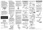
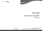
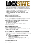
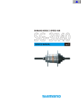
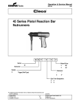
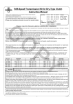
t
SHIMANO NEXUS 7-SPEED HUB
SG-7R46
SERVICE MANUAL
vol.1
Disassembly of the Inter-7 hub
SG-7R46
Tools
TL-HS10
Plier
Screwdriver
Hub spanners
Part no. Y-230 90010
13 mm x 14 mm(2 pcs.)
1.
Hold the two bevelled surfaces
of the hub axle on the sprocket
side in a vice.
Vice
2.
Note:
Do not damage the threads of
the hub axle.
Remove the lock nut for left
hand cone and the left hand
cone with dust cap from
the hub axle.
Sections A
Note:
Be careful not to
damage the sections
A of the lock nut for
left hand cone when
using the spanner.
Left hand cone
with dust cap
2
3.
Remove the ball retainer I from
the hub shell.
Ball retainer I
Hub shell
4.
Remove the right hand dust cap
with a screwdriver.
Screwdriver
Right hand dust cap
5.
Remove the hub shell.
Hub shell
Internal assembly
Internal assembly
For 182 mm axle length : Part no. Y-35D 9801
For 201 mm axle length : Part no. Y-35D 9802
3
6.
Use pliers or similar to remove
the stop spring for carrier
guide 2.
Stop spring for
carrier guide 2
Plier
Stop spring
Note:
Cover the internal assembly
with a cloth to prevent the
stop spring for carrier guide 2
from flying off during removal.
7.
Remove ring gear unit 2, carrier
unit 2 and carrier guide 2 at the
same time while turning ring
gear unit 2 slightly to the left
and right.
Carrier guide 2
Plier
Carrier guide 2
Carrier unit 2
After removing
them at the same
time, remove carrier
unit 2 and carrier
guide 2 from ring
gear unit 2.
Carrier unit 2
Ring gear unit 2
Ring gear unit 2
8.
Remove sun gear unit 2 & 3
while turning them slightly to
the left and right.
Note:
If undue force is applied during
removal, the pawls inside will
become damaged, which will
cause operation problems.
Sun gear unit 2 & 3
9.
Remove carrier unit 1.
Carrier unit 1
4
10.
Remove ball retainer M from
the driver unit.
Be careful not to bend ball
retainer M.
Ball retainer M
Driver unit
This completes the disassembly of the Inter-7 hub.
5
Assembly of the Inter-7 hub
1.
Hold the two bevelled surfaces
of the hub axle on the sprocket
side in a vice.
Vice
2.
Place ball retainer M onto the
driver unit.
Note:
Do not damage the threads of
the hub axle.
Note:
Be careful of the setting
direction.
Apply a liberal coating of internal
hub grease.
GREASE (Y-041 20800)
Ball retainer M
Be careful not to bend ball
retainer M.
Driver unit
3.
Engage the teeth of the planet
pinion in carrier unit 1 with the
teeth of the driver unit, and
then press in the driver unit
while turning it slightly to the
left and right.
Teeth of planet pinion in carrier unit 1
6
Note:
Apply a liberal coating of internal
hub grease to the planet pinions
(3 places) in carrier unit 1.
Teeth of driver unit
4.
Engage the teeth of sun gear
unit 2 & 3 with the teeth of the
planet pinion in carrier unit 1
while turning sun gear unit 2 &
3 slightly to the left and right,
and then press in carrier unit 1.
Teeth of sun gear unit 2 & 3
Teeth of planet pinion in carrier unit 1
Note:
Apply a liberal coating of internal
hub grease to the teeth of sun
gear unit 2 & 3.
GREASE (Y-041 20800)
Be careful of the setting
direction. If the setting is
reversed, installation will not be
possible.
If undue force is applied, the
pawls inside will become
damaged, which will cause
operation problems.
The gear with the smooth ring
section is at the top
5.
Place ring gear unit 2 onto
carrier unit 1.
Ring gear unit 2
Note:
Apply a liberal coating of internal
hub grease to the teeth of ring
gear unit 2.
Carrier unit 1
GREASE (Y-041 20800)
Set so that the part with the
teeth is at the top.
6.
Groove in stop ring for carrier
guide 2 should be visible
Engage the teeth of the planet
pinion in carrier unit 2,carrier
guides 2 and the teeth of ring
gear unit 2 while turning carrier
unit 2 slightly to the left and
right, and then press in ring
gear unit 2.
Note:
Apply a liberal coating of
internal hub grease to the teeth
of the planet pinion (3 places) in
carrier unit 2.
If undue force is applied, the
pawls inside will become
damaged, which will cause
operation problems.
Check:
Check that the groove in the stop
spring for carrier guide 2 is visible
from the edge of carrier unit 2
while carrier unit 2 is pushed
down.
Teeth of planet pinion
in carrier unit 2
Teeth of ring gear
unit 2
7
7.
While pushing down carrier
guide 2, insert the stop spring
into the hub axle groove at the
surface of carrier guide 2.
Note:
Be careful of the setting
direction.
2 Insert
Stop spring
Hub axle groove
Carrier guide 2
Insert securely as far as
1
it will go.
While
pushing
down
OK
8.
Install the internal assembly
while turning the hub shell
slightly to the right and left so
that seal spring R of the hub
shell is sitting in the right hand
dust cap of the internal
assembly.
Hub shell
Internal assembly
9.
Place ball retainer I onto the hub
shell.
Not OK
Note:
Apply a liberal coating of internal
hub grease to the grease groove
of the hub shell.
GREASE (Y-041 20800)
If seal spring R hooks into the
wrong part of the right hand dust
cap, push seal spring R with a
screwdriver.
Check:
After installing the hub shell, turn
the hub shell counterclockwise
and check that it turns smoothly.
Note:
Be careful of the setting direction.
Apply a liberal coating of internal
hub grease.
GREASE (Y-041 20800)
Ball retainer I
Hub shell
10.
Screw the left hand cone with
dust cap to adjust so that the
hub shell can be turned
smoothly without any play.
After adjusting, secure the left
hand cone with dust cap with
the lock nut for left hand
cone.
Sections A
Note:
Be careful not to
damage the sections
A of the lock nut for
left hand cone when
using the spanner.
Left hand cone
with dust cap
8
11.
Hold the two bevelled surfaces
of the hub axle
in a vice.
Vice
12.
Note:
Do not damage the threads of
the hub axle.
Install the right hand dust cap.
GREASE
(Y-041 20800)
Check:
After installing right hand dust cap to the hub shell, turn the hub shell clockwise and check that it
turns smoothly. If the hub shell does not turn smoothly, re-install right hand dust cap.
This completes the assembly of the Inter-7 hub.
9
Spare parts list
SHIMANO NEXUS 7-SPEED HUB w/Hi-Power Roller Brake
SG-7R46
BR-IM41-R
Inter-7 Hub
Inter-M Brake
32
TL-7S40-B
For Axle Length
201 mm
26
27
29
45
31
33
30
35 36 37
M
JA
PA
N
IN
.2
N
46 Grease
GREASE
m
04
PE-LD
7L
47
34
1
CJ-7S40
Internal Assembly
For Axle Length
201 mm
40
38
11
10
39
41
42 43
28
27
44
1
8
2 3
4
5
6
7
9
10
11
8
16
2 3
10
9
12
13
14 15
17
10
21
19
11 18
20 22
22 23 24 25
26
Q'TY
ITEM
NO.
1
2
3
4
5
6
7
SHIMANO
CODE NO.
Y-35D 98010
Y-35D 98020
Y-308 07000
Y-33E 03000
Y-33E 98070
Y-308 98040
Y-33F 98060
Y-330 98060
Y-35D 98030
8
Y-35D 98040
9
10
11
12
13
14
15
16
17
18
19
20
21
22
23
24
25
26
27
28
29
30
31
32
33
34
35
36
37
38
39
40
41
42
43
44
45
46
47
Y-330 91800
Y-35C 07000
Y-33Z 26000
Y-34L 98050
Y-34L 98060
Y-330 24000
Y-33Z 10000
Y-33Z 11000
Y-35D 98050
Y-35D 98060
Y-330 91600
Y-33Z 98030
Y-33Z 28000
Y-33F 98040
Y-330 12000
Y-33E 98120
Y-33Z 08000
Y-308 03020
Y-314 14010
Y-220 06040
Y-33Z 20500
Y-33M39600
Y-33M39700
Y-33M39510
Y-33M39610
Y-33M39710
Y-75V 13000
Y-75V 16010
Y-33F 98090
Y-33F 98100
Y-75P 98030
Y-75M98070
Y-31Z 06020
Y-308 98070
Y-308 98080
Y-322 03220
Y-322 03420
Y-322 03520
Y-322 03620
Y-330 60000
Y-330 60100
Y-321 20010
Y-74Y 98010
Y-74Y 02000
Y-74Y 98020
Y-33Z 98020
Y-74Y 98030
Y-308 89000
Y-041 20800
Y-041 20400
Y-041 40020
DESCRIPTION
Internal Assembly (Axle Length 182 mm)
Internal Assembly (Axle Length 201 mm)
Stop Ring for Carrier Guide 2
Carrier Guide 2
Carrier Unit 2
Ring Gear Unit 2
Sun Gear Unit 2 & 3
Carrier Unit 1
Carrier guide 2 / Axle & Driver Unit
(Axle Length 182 mm)
Carrier guide 2 / Axle & Driver Unit
(Axle Length 201 mm)
Ball Retainer M (3/16" x 26)
Right Hand Dust Cap B
Right Hand Dust Cap C
Axle Unit (Axle Length 182 mm)
Axle Unit (Axle Length 201 mm)
Return Spring A
Gear Shifting Cam
Feed Cam
Driver Unit w/Right Hand Dust Cap B & C
Driver Unit
Ball Retainer F (3/16" x 12)
Right Hand Cone w/Seal
Right Hand Cone Seal
Driver Plate w/Seal
Driver Plate Seal
Lock Washer
Stop Washer
Right Hand Lock Nut (6 mm)
Cap Nut (3/8")
Washer (3.2 mm) for Axle Length 201 mm
Non-turn Washer 5R (Yellow)
Non-turn Washer 6R (Silver)
Non-turn Washer 7R (Black)
Non-turn Washer 5L (Brown)
Non-turn Washer 6L (White)
Non-turn Washer 7L (Gray)
Brake Unit Fixing Nut (8.2 mm)
Grease Hole Cap
Brake Arm Clip Unit (5/8")
Brake Arm Clip Unit (3/4")
Brake Cable Adjusting Bolt Unit
Inner Cable Fixing Bolt Unit
Lock Nut for Left Hand Cone
Left Hand Cone w/Dust Cap
Ball Retainer I (3/16" x 11)
Sprocket Wheel 16T (Silver)
Sprocket Wheel 18T (Silver)
Sprocket Wheel 19T (Silver)
Sprocket Wheel 20T (Silver)
Sprocket Wheel 21T (Silver)
Sprocket Wheel 22T (Silver)
Snap Ring C
CJ-7S40 Cassette Joint Unit
Cassette Joint Pulley
Cassette Joint Bracket
Cassette Joint Fixing Ring
Inner Cable Fixing Bolt Unit for CJ-7S40
TL-7S40-B Right Hand Cone Tool
Internal Hub Grease (Net. 100g)
Roller Brake Grease (Net. 100g)
Roller Brake Grease (Net. 10g)
IL/SG Printed in Japan 0202-2128
11
SHIMANO AMERICAN CORPORATION
One Holland, Irvine, California 92618, U.S.A. Phone: +1-949-951-5003 Fax: +1-949-768-0920
Specifications are subject to change for improvement without notice.
This publication is printed on recycled paper.
MA35DA © Jan. 2004 Shimano Inc.
UCI official neutral
technical support
t