1
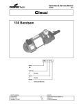
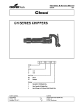
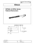
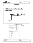
Operation & Service Manual
823154
2/01
45 Series Pistol Reaction Bar
Nutrunners
45 N P
-
X -
Series:
Nutrunner:
X
Output Drive:
3
3/8"
4
1/2"
45
Handle:
P
X -
Extension:
3
3"
Trigger (Stall Type)
Gear Train Designation:
2
4
3
6
For additional product information visit our website at http://www.clecotools.com
NORTH AMERICA
CooperTools
P.O. Box 1410
Lexington, SC 29071
EUROPE
Cooper Power Tools GmbH & Co.
Postfach 30
D-73461 Westhausen
1
Safety Recommendations
For your safety and the safety of others, read and understand the
safety recommendations and operating instructions before operating a nutrunner.
by the tool. Tool balance arms are also available to absorb the
torque reaction of the tool while balancing the weight of the tool for
improved ergonomic applications.
Always wear protective equipment:
!
!
WARNING
Impact resistant eye protection
must be worn while operating
or working near this tool.
For additional information on eye protection and face protection,
refer to Federal OSHA Regulations, 29 Code of Federal Regulations, Section 1910.133., Eye and Face Protection, and American
National Standards Institute, ANSI Z87.1, Occupational and Educational Eye and Face Protection. Z87.1 is available from the American National Standards Institute, Inc., 11 West 42nd Street, New
York, NY 10036.
!
If the tool is to be reversed, locate torque reaction bar in a position
that will resist torque reaction and prevent entrapment. See Directions on next page.
Tools with clutches can stall rather than shut-off if adjusted over
maximum power output of tool, or if there is a drop in air pressure.
Reaction bar must be properly positioned to resist torque. Operator
must release throttle to stop tool if this occurs. Do not use without
properly positioned reaction bar.
Reversible tools can have torque reactions in either direction. The
reaction bar must be properly positioned to resist the torque
reaction.
CAUTION
Personal hearing protection is
recommended when operating
or working near this tool.
Hearing protection is recommended in high noise areas 85 dBA or
greater. The operation of other tools and equipment in the area,
reflective surfaces, process noises and resonant structures can
substantially contribute to, and increase the noise level in the area.
Excessive air pressure 90PSIG or worn motor components can also
increase sound level emitted by tool. For additional information on
hearing protection, refer to Federal Regulations, Section 1910.95,
Occupational Noise Exposure, and American National Standards
Institute, ANSI S12.6, Hearing Protectors.
Cleco nutrunners are designed to operate on 90 psig (6.2 bar)
maximum air pressure. If the tool is properly sized and applied,
higher air pressure is unnecessary. Excessive air pressure increases the loads and stresses on the tool parts, sockets, and
fasteners and may result in breakage. Installation of a filter-regulator-lubricator in the air supply line ahead of the tool is recommended.
Before the tool is connected to the air supply, check the throttle for
proper operation (i.e., throttle moves freely and returns to closed
position). Clear the air hose of accumulated dust and moisture. Be
careful not to endanger adjacent personnel. Before removing a tool
from service or changing sockets, make sure the air line is shut off
and drained of air. This will prevent the tool from operating if the
throttle is accidently engaged.
It is essential for safe operation that any operator of a nutrunner use
good balance, sure footing, and proper posture in anticipation of a
torque reaction. Insure that the operator's hand will not be wedged
or pinched between the work and the tool when operating.
Reaction bar nutrunners are equipped with a torque reaction bar.
These bars can be braced against the work or other suitable points
to absorb and relieve the operator of the torque reaction transmitted
2
CAUTION
!
WARNING
Repetitive work motions and/or vibration
may cause injury to hands and arms.
Use minimum hand grip force consistent
with proper control and safe operation.
Keep body and hands warm and dry.
Avoid anything that inhibits blood circulation.
Avoid continuous vibration exposure.
Keep wrists straight.
Avoid repeated bending of wrists and hands.
Some individuals may be susceptible to disorders of the hands and
arms when performing tasks consisting of highly repetitive motions
and/or exposure to extended vibration. Cumulative trauma disorders such as carpal tunnel syndrome and tendonitis may be caused
or aggravated by repetitious, forceful exertions of the hands and
arms. Vibration may contribute to a condition called Raynaud's
Syndrome. These disorders develop gradually over periods of
weeks, months, and years. It is presently unknown to what extent
exposure to vibrations or repetitive motions may contribute to the
disorders. Hereditary factors, vasculatory or circulatory problems,
exposure to cold and dampness, diet, smoking and work practices
are thought to contribute to the conditions.
Any tool operator should be aware of the following warning signs
and symptoms so that a problem can be addressed before it
becomes a debilitating injury. Any user suffering prolonged symptoms of tingling, numbness, blanching of fingers, clumsiness or
weakened grip, nocturnal pain in the hand, or any other disorder of
the shoulders, arms, wrists, or fingers is advised to consult a
physician. If it is determined that the symptoms are job related or
aggravated by movements and postures dictated by the job design,
it may be necessary for the employer to take steps to prevent further
occurrences. These steps might include, but are not limited to,
repositioning the workpiece or redesigning the workstation, reassigning workers to other jobs, rotating jobs, changing work pace,
and/or changing the type of tool used so as to minimize stress on
the operator. Some tasks may require more than one type of tool to
obtain the optimum operator/tool/task relationship.
Safety Recommendations
The following suggestions will help reduce or moderate the effects
of repetitive work motions and/or extended vibration exposure:
• Use a minimum hand grip force consistent with proper
control and safe operation
• Keep body and hands warm and dry (cold weather is
reported to be a major factor contributing to Raynaud's
Syndrome)
• Avoid anything that inhibits blood circulation
—Smoking Tobacco (another contributing factor)
—Cold Temperatures
—Certain Drugs
Avoid
OK
Extension
Neutral
Avoid
Flexion
Avoid
Neutral
Ulnar Deviation
• Tasks should be performed in such a manner that the
wrists are maintained in a neutral position, which is
not flexed, hyperextended, or turned side to side.
• Stressful postures should be avoided — select a tool
appropriate for the job and work location
• Avoid highly repetitive movements of hands and
wrists, and continuous vibration exposure (after each
period of operation, exercise to increase blood circulation)
• Keep tool well maintained and replace worn parts
For more information on the safe use of portable air tools, see the
latest edition of ANSI B186.1, Safety Code for Portable Air Tools,
available from the American National Standards Institute, Inc. 11
West 42nd Street, New York, NY 10036.
WARNING
OVERLOADED REACTION BARS
MAY BEND OR BREAK! USE THIS
GUIDE FOR PROPER APPLICATION OF THE CLECO REACTION
BAR.
Standard Length Spindle
X = 2 1/2" Minimum
Y = 2 1/2" Maximum
Torque Capacity = 125 Ft. Lbs. Maximum
3" Longer Than
Standard Spindle
X = 4" Minimum
Y = 5 1/2" Maximum
Torque Capacity = 80 Ft. Lbs. Maximum
Avoid
OK
Radial Deviation
!
These capacities apply to Cleco Reaction Bars code
numbers: 869769-0, 869770, 202007, 202008,
202009.
!
WARNING
Substitute bars without proper
metallurgy may not be adequate.
Use Cleco reaction bars.
Due to the multitude and variety of tooling applications
involving reaction bar nutrunners,the "User's" Methods
Engineering, Standard Tooling Engineering, and/or Safety
Engineering Departments , etc. , must consider any
hazards associated with each specific application of this
product and provide adequate operator protection,
reaction points and strengths, and operator training in the
safe use of this product.
This information is a compilation of general safety practices obtained from various sources available at the date of production.
However, our company does not represent that every acceptable
safety practice is offered herein, or that abnormal or unusual
circumstances may not warrant or require additional procedures.
Your work may require additional specific safety procedures. Follow
these procedures as required by your company.
203185
203289
WARNING
!
OVER
Repetitive work motions and/or vibration
can cause injury to hands and arms.
Use minimum hand grip force consistent with
proper control and safe operation.
Keep body and hands warm and dry.
Avoid anything that inhibits blood circulation.
Avoid continuous vibration exposure.
Keep wrists straight.
Avoid repeated bending of wrists and hands.
CAUTION
WARNING
Personal hearing protection is
recommended when operating
or working near this tool.
!
!
Impact resistant eye protection
must be worn while operating
or working near this tool.
Hearing protection is recommended in high noise
areas (above 85 dBA). Close proximity of other
tools, reflective surfaces, process noises, and
resonant structures can substantially contribute
to the sound level experienced by the user.
203185-4
Read Operating Instructions carefully. Follow
the Safety Recommendations for your safety
and the safety of others.
READ
OPERATING
INSTRUCTIONS
Do not remove this tag until
the operator of this tool has
read these safety precautions.
Warning Labels
The warning labels found on these tools are an essential part of this
product. Labels should not be removed. Labels should be checked
periodically for legibility. Replace warning labels when missing or
when the information can no longer be read. Replacement labels
can be ordered as any spare part.
The reaction bar is secured to the tool and braced
against the work in the opposite direction of spindle
rotation. This will transfer the torque reaction from the
tool to the work.
3
OPERATING INSTRUCTIONS
45 STALL-TYPE NUTRUNNERS
The 45 stall-type nutrunner is designed to develop maximum rated
torque at 90 psig. Torque output is controlled by a pressure regulator in
the air supply line. Adjust the regulator until the desired torque is
reached.
REASSEMBLY
The tool is reassembled in the reverse order of disassembly. Clean all
parts thoroughly in solvent and inspect for damage or wear. Check all
bearings for wear which can be detected by excessive end play and/or
roughness which would indicate a brinelled condition. The rotor blades
should be replaced every repair cycle or if they measure less than 7/32"
(5.6mm) at either end.
AIR SUPPLY
For maximum performance, use a 3/8" I.D. air hose no longer than 8' in
length. If additional length is required, a 1/2" or larger hose should be
connected to the 3/8" hose.
The air hose should be cleared of accumulated dirt and moisture, then
a few drops of 10W machine oil should be poured into the tool's air inlet
before connecting the hose to the tool.
LUBRICATION
An automatic in-line filter-lubricator is recommended as it increases tool
life and keeps the tool in sustained operation. The in-line lubricator
should be regularly checked and filled with a good grade of 10W
machine oil. For proper adjustment of the in-line lubricator, place a
sheet of paper next to the exhaust ports and hold the throttle open
approximately 30 seconds to one minute. All the oil needed is enough
to produce a light stain on the paper. If the oil mist is visible to the naked
eye it is generally an excessive amount of oil. Excessive amounts of oil
should be avoided.
Must be replaced if
7/32" (5.6mm) or less
at either end.
All gear teeth, bearings, and pins should receive a close inspection and
be replaced if necessary.
To assemble the motor, install the rear rotor bearing into the rear
bearing plate. Make sure the outer bearing race is firmly seated in the
bearing plate. Clamp the rotor body lightly in the vise with the threaded
end up and slip the rear bearing plate assembly onto the rotor shaft far
enough for the bearing lock nut to start. Tighten the lock nut until there
is approximately .0015" clearance between the rotor and bearing plate.
The outer bearing race should be firmly seated and the rotor bumped
forward when checking this clearance as shown in drawing below.
Application of the tool should govern how frequently it is greased. It is
recommended that the idler gears and right angle gears receive a
generous amount of No. 2 Moly grease through the grease fittings after
40 hours of operation.
STORAGE
In the event that it becomes necessary to store the tool for an extended
period of time (overnight, weekend, etc.), it should receive a generous
amount of lubrication at that time and again when returned to service.
The tool should be stored in a clean and dry environment.
SERVICE INSTRUCTIONS
.0015"
Clearance
SOFT
JAWED
VISE
DISASSEMBLY — GENERAL
Stall Tools
To disassemble the tool, clamp the handle, 869755, in a vise and
unscrew the gear case, 869762. The motor unit may now be removed
from the handle.
The gear train should be removed from the rear of the gear case,
202325. The 2nd reduction idler gears are removed from the spider by
driving the idler gear pins out the rear of the spider.
To disassemble the motor unit, clamp the cylinder, 864236, in the vise
with the gear end of the rotor up. Note: Rotor pinion, 867524, used on
the - 4 and -6 gear trains should be removed from the rotor. Use a softfaced hammer to drive the rotor out of the front rotor bearing, No.
619377. Be careful not to damage the rotor. The front bearing plate,
869054, cylinder, 203169, and rotor blades, may now be removed from
the rotor. Clamp the body of the rotor in the vise and unscrew the rotor
lock nut, 865352, to remove the rear bearing plate, 869055, and rear
rotor bearing, 843444.
Unscrew the inlet bushing, 833471, for inspection and cleaning of the
inlet screen, 869548. Wash the screen in a solvent and blow out in the
reverse of normal air flow. If the screen is damaged or torn it should be
replaced. The muffler, 869764, may be removed for cleaning by
removing the retainer ring, 619016, and exhaust screen, 412775.
4
Pack both rotor bearings with a good grade of No. 2 Moly grease after
assembly of the motor unit.
Note: During reassembly of the complete tool, it is important that the
motor be free. After the tool is completely assembled, the square drive
spindle should turn freely using a small hand wrench. If the spindle does
not turn freely, the motor should be checked for proper spacing. Do not
run the tool until the spindle turns freely. Failure to do this could result
in damage to motor components.
During reassembly of the gear train all of the various gears and bearings
should receive a generous amount of No. 2 Moly grease.
Pour a few drops of 10W machine oil into the air inlet after complete
assembly to insure immediate lubrication of all motor parts when air is
applied.
45 & 55 INLINE REACTION BAR NUTRUNNER GEAR TRAINS
Part No.
844774
844774
844774
844774
Part No.
203106
203107
203106
203107
Part No.
867526
867526
867523
867523
Model
-2
-3
-4
-6
204809
Model
-2
-3
-4
-6
Part No.
NONE
NONE
867524
867524
832125
Model
-2
-3
-4
-6
844774
865576
844778 Part No.
203336
844773
203337
203336
203337
Model
-2
-3
-4
-6
869767
869761
Model
-2
-3
-4
-6
(Incl. in 202502)
Part No.
861525
861485
861484
861486
Model
-2
-3
-4
-6
202324
202502
(Incl. in 202502)
REACTION BAR
Complete
Reaction
Head
Reaction Bar Bar Only
Only
Aluminum 869769
202009
202007
Steel
869770
202008
202007
Material
Pin
884126
884126
869758
869759
869756
869757
844016
844011
844017
844014
844013
844013
3/8" Sq. Dr.
3/8" Sq. Dr. 3" Ext.
1/2" Sq. Dr.
1/2" Sq. Dr. 3" Ext.
3/8"
1/2"
3/8"
1/2"
3/8"
1/2"
PARTS LIST — 45 & 55 GEAR TRAINS
PART NO.
NAME OF PART
202007
202008
202009
202324
202502
203106
203107
204809
832125
844011
844013
844014
844016
844017
844773
844774
844778
861484
861485
Reaction Bar Head
Reaction Bar (Steel)
Reaction Bar (Aluminum)
Spindle Bushing
Gear Case (incl. 869767 & 202324)
- 2 — 2nd Red. Gear- 18T (incl. 844774)
- 3, - 6 — 2nd Red. Gear- 15T (incl. 844774)
2nd Red. Gear
- 2, - 3, - 4, - 6 —1st Red. Gear Pin
Socket Retainer Pin
Retainer Plug
Spring
Socket Retainer Pin
Spring
Ball Bearing
Gear Bearing
Retainer Ring
- 4 —1st Red. Spider - 13T (incl. Pin)
- 3 —1st Red. Spider- 19T (incl. Pin)
QTY. PART NO.
1
1
1
1
1
3
3
3
3
1
1
1
1
1
1
9
1
1
1
861486
861525
867523
867524
867526
869756
869757
869758
869759
869761
869767
869769
869770
NAME OF PART
QTY.
- 6 —1st Red. Spider- 19T (incl. Pin)
- 2 —1st Red. Spider- 13T (incl. Pin)
- 4, - 6 —1st Red. Gear- 17T (incl. 844774)
- 4, - 6 — Rotor Pinion 6T
- 2, - 3 —1st Red. Gear - 21T (incl. 844774)
1/2" Sq. Dr. Spindle (incl. Ret. Pin)
1/2" Sq. Dr. Spindle " Ext. (ind. Ret. Pin)
3/8" Sq. Dr. Spindle (incl. Ret. Pin)
3/8" Sq. Dr. Spindle " Ext. (incl. Ret. Pin)
Lock Nut
Grease Seal
Aluminum Reaction Bar (incl. 202007, 202008,
1
1
3
1
3
1
1
1
1
1
1
884126)
1
1
Steel Reaction Bar
(incl. 202007, 202008,
884126)
884126
Pin
1
5
6
7
CooperTools
670 Industrial Drive
Lexington, SC 29072
Phone: (803) 359-1200
Fax: (803) 359-2013
www.clecotools.com
8