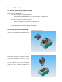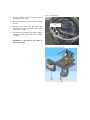
1
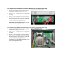
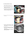
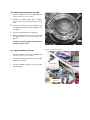
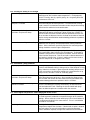
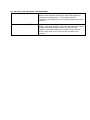
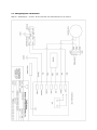
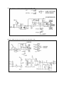
Service Manual
Immersion Circulators
Heat-Only Circulators
Refrigerated/Heated Circulators
With
Standard Controllers
Before performing any service to the unit, reset the controller to its default settings. It is our experience that many
problems can be resolved by doing so. See Sec. 4.1 of this manual for instructions.
Refrigeration service should only be performed by a qualified refrigeration technician.
The refrigeration system contains no user-serviceable parts.
This manual is intended for use by qualified service personnel only. Disconnect power cord before removing cover,
exposed voltage when cover is removed. Hazard from moving parts present when cover is removed.
110-426 08/06
Table of Contents
Section 1 – Identifying your unit
Section 2 – Specifications
2.1 – General Description, Heating and Refrigerated Circulators
2.2 – General Description, Immersion Circulators
2.3 – General Specifications, all units
Section 3 – Maintenance
3.1 – Heater
3.2 – Pump Motor
3.3 – Cleaning
3.4 – Maintaining Clear Bath Water
3.5 – Condenser, Air Vents, and Reusable Filter (Refrigerated Circulators Only)
3.6 -- Calibration
Section 4 – Controller
4.1 – Resetting unit to Factory Defaults (all units)
4.2 – Removing Controller Cover (all units)
4.3 -- Removing Controller from Unit (heating & refrigerated units only)
4.4 – Replacing Front Bezel Assembly/ Main PC Board (all units)
4.5 – Replacing Compressor Control PC Board (all 6 liter refrigerated units only)
4.6 – Replacing PWM Control PC Board (all 13 and 28 liter refrigerated units)
4.7 – Replacing Pump Motor (all units)
4.8 – Replacing Pump Impeller
4.9 – Replacing Heater (all units)
Section 5 – Refrigerant Charge (for refrigerated units only)
Section 6 – Basic Troubleshooting
6.1 – Unit Not Pumping (all units)
6.2 – Unit Not Heating (all units)
6.3 – Unit Heats Constantly (all units)
6.4 – Unit Does Not Cool (all 6 liter refrigerated units)
6.5 – Unit Does Not Cool (all 13 & 28 liter refrigerated units)
6.6 – Compressor Runs Constantly (all refrigerated units)
Section 7 – Technical Drawings
8.1 – Refrigeration Assemblies
8.2 – Wiring Diagrams & Schematics
Section 1 – Identifying Your Unit
Within this manual, units are identified using the following format:
“Immersion circulator” refers to the immersion circulator with standard controller, model 7306
“xx Liter Heating Circulator” (i.e. 13 liter heating circulator) refers to heat only circulators with internal reservoir,
models 8006, 8106, 8206, 8306
“xx Liter Refrigerated Circulator” (i.e. 28 liter refrigerated circulator) refers to heating/refrigerating circulators with
internal reservoir, models 9006, 9106, 9506, 9606, 9706
Model 9706, 13 liter low temperature models will be identified as “13 liter low temp refrigerated circulator”.
“Controller” refers to the upper portion of the unit that includes the PC boards, pump, and heater. In the case of
Immersion Circulators, the entire unit is the controller.
Section 2 – Specifications
2.1 – General Description, Heating and Refrigerated Circulators
Refrigerated and Heat Only Circulating Baths with the Standard controller are designed for use as stand-alone baths
or to provide precise temperature control of fluids for closed loop circulation to external equipment. Refrigeration is
normally required for operation at temperatures below 30°C.
All Circulating Bath models feature a reservoir, which may be used for immersing samples while the unit is connected
to an external device. Circulating Bath models are equipped with a 6, 13, or 28 liter reservoir. All wetted parts are
corrosion-resistant 300 series stainless steel.
2.2 – General Description, Immersion Circulators
Immersion Circulators with Standard Controllers are designed for use in user-supplied reservoirs. These units can be
used with many sizes and shapes of reservoirs, making them extremely versatile and useful for a wide variety of
applications. They may be used for closed loop applications. Operation of the Controller is the same as that for
Circulating Bath models.
2.3 – General Specifications, all units
Model Type
Temperature
Range
Amps @
120v 60Hz
Amps @
240v 50Hz
6L Refrigerated (all)
-20° to 150°C
12
9.9
13L Refrigerated
-30° to 150°C
13
9.8
28L Refrigerated
-25° to 150°C
13
9.8
13L Low Temp Refrigerated
-40° to 150°C
14
9.9
All Heat Only Units
Ambient +5° to 150°C
11
9.8
Immersion Circulators
Ambient +5° to 150°C
11
7.5
The following specifications apply to all units:
Temperature Stability1
Readout Accuracy
Heater
Maximum Pressure Flow Rate
Over-Temperature Protection
Low-Liquid Protection
Pump Speed
Pump Inlet and Outlet
±0.05°C
LED, °C or °F, ±0.25°C
1100W – 115V,
1600W – 240V
15 LPM
Yes, user-adjustable
Yes
2 speeds, 9 or 15 lpm
¼ inch FPT rear discharge (except immersion circulator)
1. Temperature stability may vary depending on bath volume, surface area, insulation, and type of fluid.
NOTE: Performance specifications determined at ambient temperature of 20°C (68°F).
Environmental Conditions:
● Indoor Use Only
● Maximum Altitude: 2000 meters
● Relative Humidity: 80% for temperatures to 30°C
● Class 1: Residential, Commercial, Light Industrial
● Over Voltage: Category ll
● Operating Ambient: 5° to 30°C
● Pollution Degree: 2
● Class 2: Heavy Industrial
Section 3 – Maintenance
3.1 – Heater
The heater should be kept clean. If deposits build up on the heater, they may be removed by scrubbing with a nonmetallic abrasive pad. Do not use steel wool.
3.2 – Pump Motor
The pump bearings are permanently lubricated with high-temperature silicone grease and do not require additional
lubrication. Should the bearings become noisy, replacement of the entire pump motor is recommended. This will
reduce repair labor costs and retain fluid pumping reliability.
3.3 – Cleaning
Only mild detergents and water or an approved cleaner should be used on the painted and stainless steel surfaces of
the Circulator. Do not allow cleaning liquids or sprays to enter the Controller vents.
3.4 – Maintaining Clear Bath Water
When water is used as the bath fluid, optimal conditions are present for algae growth. To prevent algae
contamination and minimize the need for draining the reservoir, an algaecide should be used.
Do NOT use chlorine bleach in the reservoir or on any pump parts.
3.5 – Condenser, Air Vents, and Reusable Filter (Refrigerated Circulators Only)
To keep the refrigeration system operating at optimum cooling capacity, the condenser, the front
and back air vents, and reusable filter should be kept free of dust and dirt. They should be checked
on a scheduled basis and cleaned as required.
The reusable filter is easily accessed from the bottom/front of the unit. Turn the filter-retaining clip
away from the filter cutout and remove the filter as shown in figure B. Use a mild detergent and
water solution to wash off any accumulated dust and dirt and then rinse and dry thoroughly before
reinstalling.
Figure B – Removing Air Filter
3.6 – Calibration
Calibration allows the user to match the Controller’s bath temperature display to an external reference thermometer.
Calibration is performed as follows:
Set the desired operating fluid temperature set point and allow temperature to stabilize.
Press the P2 and P3 simultaneously and release and repeat until the display reads (oCx.x). Press P1 and hold until (Cal) is
displayed. This will take about 2 seconds.
At one second intervals, the displayed value will alternate between the actual bath fluid temperature and the current offset
value, which is the difference between the factory calibration setting and the user’s reference temperature sensor. The
maximum offset is ±0.9°C from factory calibration.
To change the calibration offset value, rotate the Select/Set Knob until the display matches the reading on the reference
temperature sensor. The display will continue to alternate between the offset value and the calibrated display temperature.
Press the Select/Set Knob or the P1 Button to accept the entered value. When the new calibration is stored and the mode is
exited, (dONE) will appear on the display.
NOTE: The displayed offset value will also be accepted if there no activity for 20 seconds.
Section 4 – Controller
4.1 – Resetting unit to Factory Defaults (all units)
Before performing any service to the unit, reset the controller to factory defaults. It is our experience that a number of common
problems can be resolved by doing so.
To reset the unit to default settings and operate in °C:
Set Circuit Breaker/Power Switch on the rear of the Controller in the OFF position
Press and hold the P2 Button while turning the power back ON
To reset the unit to default settings and operate in °F:
Place the Circuit Breaker/Power Switch in the OFF position
Press and hold the P3 Button while turning the power back ON
Note: When defaulting the unit, the high limit value and all temperature presets revert to the factory-default values.
If a calibration value has been entered, the value will be retained.
4.2 – Removing Controller Cover (all units)
Figure E – Removing Controller Cover
Remove the 2 screws that secure the cover to the
controller chassis. Slide the cover backward and then
lift up to remove.
4.3 – Removing Controller from Unit (Heating and Refrigerated Units Only)
Figure F – Removing Controller From Unit
Remove the 4 knurled nuts that secure the controller
to the lower assembly. For refrigerated models,
disconnect the wiring that is routed to the lower
refrigeration assembly.
Lift the controller up and away from the deck plate.
Note: To remove the controller and top deck plate at
once, remove the 4 Phillips screws located on the
outside edge of the deck plate instead of the 4
knurled nuts that hold the controller to the deck plate.
4.4 – Replacing Front Bezel Assembly (Main PC Board – all units)
1.
Figure G – Disconnecting wiring
Remove controller cover (see Sec. 4.2)
Note the color and location of the wires which are
connected to the terminals on the back of the
bezel, including the RJ45 cable. Disconnect all
wires. (See Fig. G)
2.
Loosen the Phillips screw that
temperature probe to retaining clip.
secures
Disconnect all
wires
Figure H – Temperature probe retaining clip
Top of temperature
probe
Retaining clip
screw
3.
Remove controller from unit (except immersion
circulators) (see Sec. 4.2).
4.
Remove 4 screws that secure bezel to controller
chassis.
5.
Remove screw and clips that hold OTP
thermostat to heater, then remove OTP sensor
from heater (see Fig. I)
6.
Remove bezel assembly, being careful to pull the
temperature probe up and out of the controller
(see Fig. J)
Figure I – OTP Retaining Clip
Remove screw and
clip
Installation of a new bezel is the reverse of
the previous steps.
Figure J –Removing Bezel From Controller
4.5 – Replacing the Compressor Control PC Board (6 liter refrigerated units only)
1.
Remove the controller and deck plate from the
refrigeration assembly along (see Sec. 4.3).
2.
Slide the case assembly from the refrigeration
assembly.
3.
Note the color and location of the wires that are
connected to the Compressor Control PC Board.
Disconnect the wires and remove the screws that
secure the PCB to the refrigeration unit.
Figure K –Compressor Control PC Board
Installation of a new compressor control PCB
is the reverse of the previous steps.
4.6 – Replacing the PWM Control PC Board (13 & 28 liter refrigerated units only)
1.
Remove the controller and deck plate from the
refrigeration assembly (see Sec. 4.3).
2.
Slide the case assembly from the refrigeration
assembly.
3.
Note the color and location of the wires that are
connected to the PWM Control PC Board.
Disconnect the wires and remove the screws that
secure the PCB to the refrigeration unit.
Installation of a new PWM control PCB is the
reverse of the previous steps.
Figure L – PWM Control PC Board
4.7 – Replacing Pump Motor (all units)
1.
Remove controller from unit (if applicable) and
remove cover (see Sec. 4.2 & 4.3)
2.
Note the color and location of the wires which are
connected to the pump motor at PMPH and
PMPN. Disconnect these 2 wires.
3.
Unsolder the wires connected from the motor to
the pump speed switch. Note, only the top and
bottom wire on the switch should be removed;
the center wire should NOT be removed.
Figure M –Disconnecting Pump Motor Wring
Unsolder outer 2
wires on pump
speed switch
PMPH
PMPN
Pump Motor Ground Wire
4.
Remove the 4 nuts that secure the pump motor
to the chassis.
Figure N –Removing Pump Motor from Controller
2 of the 4 nuts that hold pump motor to chassis
Figure O – Detaching lower impeller
5.
Position the controller upside down.
Remove
the screw that secures the Impeller to the pump
shaft. It is not necessary to futher disassemble
the pump housing.
6.
Note position of red rubber slinger located where
motor shaft meets the bottom of the controller
chassis. Remove the pump motor from the
controller chassis.
Install the new pump motor by following the
previous steps in reverse.
Impeller screw
4.8 – Replacing Pump Impeller (all units)
1.
Remove controller from unit (if applicable) and
remove cover (see Sec. 4.2 & 4.3)
2.
Position the controller upside down.
Remove
the screw that secures the impeller to the pump
shaft.
3.
4.
Figure P – Pump Assembly
Remove all screws that secure the impeller cover
assembly to the heater/standoff and OTP sensor
(see Fig. P)
5.
Remove impeller bottom cover and plate.
6.
Before removing the impeller, note the direction
the impeller blades are facing. Remove the
impeller.
Install the new upper impeller by following the
previous steps in reverse.
4.9 – Replacing Heater (all units)
1.
Remove controller from unit (if applicable) and
remove cover (see Sec. 4.2 & 4.3)
2.
Disconnect the two brown wires from the heater
terminals (see Fig. Q)
3.
Loosen the Phillips screw that secures the heater
to retaining clip.
Figure Q – Disconnecting Heater Wires
Wires
Figure R –Heater
Loosening
Heater Retaining Clip
Heater retaining
clip screw
4.
Figure S – Loosening Heater Retaining Clip
Position the controller upside down.
Remove the screw that holds the OTP
sensor to the pump/heater assembly, then
move the OTM sensor away from the heater.
For immersion
circulators, Remove
these two screws and
bracket.
For immersion circulators only:
Remove the screws holding the bracket to
the pump assembly.
5.
Remove OTP
sensor
Remove heater from unit by sliding it down
out of the controller.
Install the new heater by following the
previous steps in reverse.
Section 5 – Refrigerant Charge (refrigerated units only)
Please note: Units are factory charged by refrigerant weight, not pressure. There are no published refrigerant
pressure specifications available as they will vary with fluid temperature.
Refrigerant Type
Charge (Grams)
Charge (Ounces)
6 Liter
R-134a
229 g
8.02 oz
6 Liter Low Profile
R-134a
229 g
8.02 oz
13 Liter
R-134a
343 g
12.01oz
13 Liter Low Temperature
R-404a
350 g
12.25 oz
28 Liter
R-134a
343 g
12.01 oz
Models
Section 6 – Basic Troubleshooting
6.1 – Stability problems (unit will not hold temperature within specified tolerances)
Confirm problem is with stability, not
accuracy
Stability is the ability of the unit to hold a constant temperature within
a specified tolerance. Stability is often confused with accuracy, which
is the ability of the unit to display temperature within a given tolerance
based on a known method of measurement. If temperature is being
held at a constant temperature with little fluctuation, but the displayed
temperature differs from that of a thermometer or separate device
also reading temperature, the temperature display of the unit can be
offset by using the calibration offset function.
Make sure the lid is used and that the
fluid path is insulated
The included lid should always be used. Insulation should be used on
the entire fluid path wherever possible. If an external tank is being
used, it must be insulated and covered to achieve maximum stability.
Stability specifications are based on the circulator's internal reservoir.
External stability may be higher due to heat loss or gain as the fluid
travels away from the circulator.
Check fluid properties
PolyScience specifications are based on tests performed with water
or water/glycol at 20°C ambient room temperatures. Fluid properties,
such as viscosity, density, specific gravity, etc. can greatly effect the
performance of the unit.
Use bypass tube when circulating
within the circulator
If the circulator is not being used to circulate fluid to another device or
tank, the included bypass tubing should always be attached to the
inlet and outlet of the unit. Blocking the inlet and outlet with plugs
does not allow for optimum circulation within the reservoir and can
affect stability.
Check tubing size, length, and look for
restrictions and pressure drops
Achieving good stability with external applications requires that
adequate fluid flow be maintained. Tubing smaller than 1/4 MPT ID
will cause flow restrictions and will affect the performance of the unit.
Also, consider the distance from the circulator and number of external
devices being controlled when troubleshooting performance problems
with the circulator.
Increase Auto-Refrigeration setting
Refrigerated units will achieve maximum stability when the
refrigeration system is allowed to run, even at high temperatures. If
possible, the auto-refrigeration setting should be set to the highest
possible value.
Set pump speed to maximum
Set pump speed to maximum. Greater circulation can improve
stability, especially when circulating to external devices or tanks.
6.2 – Accuracy problems (displayed temperature varies from that of an external thermometer
or device)
Use calibration offset function
Accuracy is the ability of the unit to display temperature within given
tolerances to a NIST traceable thermometer. The unit includes a
calibration offset function which can be used to adjust the displayed
temperature to match the users own temperature measurement
equipment.
6.3 – Heating too slowly
Check fluid properties
PolyScience specifications are based on tests performed with water
or water/glycol at 20°C ambient room temperatures. Fluid properties,
such as viscosity, density, specific gravity, etc. can greatly effect the
performance of the unit.
Make sure the lid is used and that the
fluid path is insulated
The included lid should always be used. Insulation should be used on
the entire fluid path wherever possible. If an external tank is being
used, it must be insulated and covered to reduce the possible cooling
effect from the ambient air.
Check tubing size, length, and look for
restrictions and pressure drops
Achieving responsive heating with external applications requires that
adequate fluid flow be maintained. Tubing smaller than 1/4 MPT ID
will cause flow restrictions and will affect the performance of the unit.
Also, consider the distance from the circulator and number of external
devices being controlled when troubleshooting performance problems
with the circulator.
6.4 – No Heating
Increase safety set point (OTP)
PolyScience circulators include a redundant over-temperature
feature. If the safety set point is set too low, the heater will be turned
off when the bath temperature reaches the safety set point,
regardless of the other settings on the control. Unless there are
specific safety concerns, the safety set point should be set at
maximum.
6.5 – Cooling too slowly or not enough
Check fluid properties
PolyScience specifications are based on tests performed with water or
water/glycol at 20°C ambient room temperatures. Fluid properties,
such as viscosity, density, specific gravity, etc. can greatly effect the
performance of the unit.
Make sure the lid is used and that the
fluid path is insulated
The included lid should always be used. Insulation should be used on
the entire fluid path wherever possible. If an external tank is being
used, it must be insulated and covered to reduce the possible heating
effect from the ambient air and condensation.
Check tubing size, length, and look for
restrictions and pressure drops
Achieving responsive cooling with external applications requires that
adequate fluid flow be maintained. Tubing smaller than 1/4 MPT ID
will cause flow restrictions and will affect the performance of the unit.
Also, consider the distance from the circulator and number of external
devices being controlled when troubleshooting performance problems
with the circulator.
Increase the auto-refrigeration setting
PolyScience circulators include an auto-refrigeration setting that
allows the user to specify at what temperatures cooling should be
active. Unless otherwise specifically required, the auto-refrigeration
setting should be set to the highest temperature.
Check for refrigerant leaks
Sudden changes in the cooling capacity of the unit, without changes
in the application, often indicate a loss of refrigerant. To distinguish
between a refrigerant loss and compressor failure, listen for unusual
noise from the compressor. Run the unit with no load to determine if
any cooling is taking place. If there is cooling and no unusual noise
from the compressor, a refrigerant leak is likely.
6.6 – Circulation / pump problems
Set pump speed to maximum
Lower pump speeds provide lower flow rates. This is especially
useful if small diameter tubing is being used, or if the fluid path is fairly
long. Note that circulators in general provide relatively low pressures.
If the user requires the fluid to be moved over a great distance or up
steep inclines, consider a chiller or secondary pump.
Check tubing size, length, and look for
restrictions and pressure drops
Tubing smaller than 1/4 MPT ID will cause flow restrictions and will
affect the performance of the unit. Also, consider the distance from
the circulator and number of external devices being controlled when
troubleshooting performance problems with the circulator.
Use bypass tube when circulating
within the circulator
If the circulator is not being used to circulate fluid to another device or
tank, the included bypass tubing should always be attached to the
inlet and outlet of the unit. Blocking the inlet and outlet with plugs
does not allow for optimum circulation within the reservoir.
6.7 – Can't Adjust Temperature / LLO is displayed on the screen
Disable local lockout
PolyScience circulators feature a control panel lockout option that can
be used to prevent accidental or unwanted changes to the controller
settings. When active the screen will display LLO or Local Lockout. It
is enabled and disabled in the same manner: Press in and hold the
set knob for 10 seconds.
Check high limit
The high limit setting allows the user to limit the functional
temperature range of the circulator. If the desired set point is beyond
the limit setting, the user will not be able to set that temperature.
Unless otherwise required, the high limit should be set to maximum.
6.8 – No power / unit shuts down / unit trips breaker
Check line cord and outlet
Ensure that the included line cord is firmly plugged in at both ends.
Make sure that the power outlet being used provides power that
matches the unit requirements. The circulator's electrical
requirements are located on the serial number tag at the back of the
controller.
Increase safety set point (OTP)
PolyScience circulators include a redundant over-temperature
feature. If the safety set point is set too low, the heater will be turned
off when the bath temperature reaches the safety set point,
regardless of the other settings on the control. Unless there are
specific safety concerns, the safety set point should be set at
maximum.
Section 7 – Technical Drawings
7.1 – Refrigeration Assemblies
1
Compressor
5
Capillary Tube (if applicable)
2
Condenser
6
High Side Line
3
Filter Dryer
7
Low Side Line
4
Solenoid Valve (if applicable)
8
Fan assembly
Fig. T – 6 Liter Refrigerated Refrigeration Assembly (9106)
7
2
8
1
6
5
3
Fig. U – 6 Liter Low Profile Refrigerated Refrigeration Assembly (9006)
7
1
2
6
8
5
3
1
Compressor
5
Capillary Tube (if applicable)
2
Condenser
6
High Side Line
3
Filter Dryer
7
Low Side Line
4
Solenoid Valve (if applicable)
8
Fan assembly
Fig. V – 13 Liter & 13 Liter Low Temp Refrigerated Refrigeration Assembly (9506 & 9706)
4
8
7
1
2
6
3
1
Compressor
5
Capillary Tube (if applicable)
2
Condenser
6
High Side Line
3
Filter Dryer
7
Low Side Line
4
Solenoid Valve (if applicable)
8
Fan assembly
Fig. W – 28 Liter Refrigerated Refrigeration Assembly (9606)
6
4
8
7
2
3
1
7.2 – Wiring Diagrams & Schematics
Diagram 1 – Wiring Diagram – Controller - Models 7306, 8006, 8106, 8206, 8306 (All heat only circulators)
Diagram 2 – Wiring Diagram, Controller – All Refrigerated Units (Model 9006, 9106, 9506, 9606, 9706
Diagram 3 – Pump power schematics
Diagram 4 – Heater power schematics
Diagram 5 –Compressor control pc board schematic (models 9006 & 9106)
Diagram 6 –PWM control pc board schematic (models 9506, 9606, & 9706)