1
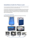
Service Manual Immersion Circulators Heat-Only Circulators Refrigerated/Heated Circulators With Digital or Programmable Controllers Before performing any service to the unit, reset the controller to its default settings. It is our experience that many problems can be resolved by doing so. See Sec. 4.1 of this manual for instructions. Refrigeration service should only be performed by a qualified refrigeration technician. The refrigeration system contains no user-serviceable parts. This manual is intended for use by qualified service personnel only. Disconnect power cord before removing cover, exposed voltage when cover is removed. Hazard from moving parts present when cover is removed. 110-345 12/23/09 Table of Contents Section 1 – Identifying your unit Section 2 – Specifications 2.1 – General Description, Heating and Refrigerated Circulators (9102, 9112, 9002, 9012, 9502, 9512 9602, 9612, 9702, 9712, 8002, 8012 8102, 8112, 8202, 8212) 2.2 – General Description, Immersion Circulators (7312) 2.3 – General Specifications, all units Section 3 – Maintenance 3.1 – Heater 3.2 – Pump Motor 3.3 – Cleaning 3.4 – Maintaining Clear Bath Water 3.5 – Condenser, Air Vents, and Reusable Filter (Refrigerated Circulators Only) 3.6 -- Calibration Section 4 – Controller 4.1 – Resetting unit to Factory Defaults 4.2 – Removing Controller Cover (all units) 4.3 -- Removing Controller from Unit (heating & refrigerated units only) 4.4 – Replacing Front Bezel Assembly/ Main PC Board (all units) 4.5 – Replacing Power Supply PC Board (all units) 4.6 – Replacing Compressor Control PC Board (9002, 9012, 9102, 9112) 4.7 – Replacing PWM Control PC Board (9502, 9512, 9602, 9612, 9702, 9712) 4.8 – Replacing Pump Motor (all units) 4.9 – Replacing Upper Pump Impeller 4.10 – Replacing Heater (all units) Section 5 – Refrigerant Charge (for refrigerated units only) Section 6 – Basic Troubleshooting 7.1 – Unit Not Pumping (all units) 7.2 – Unit Not Heating (all units) 7.3 – Unit Heats Constantly (all units) 7.4 – Unit Does Not Cool (9002, 9012) 7.5 – Unit Does Not Cool (9502, 9512, 9602, 9612, 9702, 9712 ) 7.6 – Compressor Runs Constantly (all refrigerated units) Section 7 – Advanced Troubleshooting 7.1 – Unit Not Pumping (all units) 7.2 – Unit Not Heating (all units) 7.3 – Unit Heats Constantly (all units) 7.4 – Unit Does Not Cool (9002, 9012, 9102, 9112 ) 7.5 – Unit Does Not Cool (9502, 9512, 9602, 9612, 9702, 9712 ) 7.6 – Compressor Runs Constantly (all refrigerated units) 7.7 - Diagnosis Mode Section 8 – Technical Drawings 8.1 – Refrigeration Assemblies 8.2 – Wiring Diagrams & Schematics Section 9 – RS232 9.1 – Setting up and verifying COM port settings 9.2 – Using HyperTerminal to check RS232 communication Section 1 – Identifying Your Unit Within this manual, units are identified using the following format: “Immersion circulator” refers to the programmable immersion circulator “xx Liter Heating Circulator” (i.e. 13 liter heating circulator) refers to heat only circulators with internal reservoir “xx Liter Refrigerated Circulator” (i.e. 28 liter refrigerated circulator) refers to heating/refrigerating circulators with internal reservoir. 13 liter low temperature models will be identified as “13 liter low temp refrigerated circulator”. “Controller” refers to the upper portion of the unit that includes the PC boards, pump, and heater. In the case of Immersion Circulators, the entire unit is the controller. Please see Figure A below for additional assistance with identifying your unit. Figure A – Circulator Examples Immersion Circulator Heating Circulators 6 Liter 13 Liter 28 Liter Refrigerated Circulators 6 Liter 6 Liter Low Profile 13 Liter & 13 Liter Low Temp (please contact your vendor for additional assistance determining which unit you have) 28 Liter Section 2 – Specifications 2.1 – General Description, Heating and Refrigerated Circulators Refrigerated and Heat Only Circulating Baths with the Programmable or Digital Controller are designed for use as stand-alone baths or to provide precise temperature control of fluids for open or closed loop circulation to external equipment. Refrigeration is normally required for operation at temperatures below 30°C. All Circulating Bath models feature a reservoir, which may be used for immersing samples while the unit is connected to an external device. Circulating Bath models are equipped with a 6, 13, or 28 liter reservoir. All wetted parts are corrosion-resistant 300 series stainless steel. 2.2 – General Description, Immersion Circulators Immersion Circulators with Programmable Controllers are designed for use in user-supplied reservoirs. These units can be used with many sizes and shapes of reservoirs, making them extremely versatile and useful for a wide variety of applications. They may be used for open and closed loop applications. Operation of the Controller is the same as that for Circulating Bath models. The Immersion Circulator features an expandable mounting bridge that may be adjusted to span the top of the usersupplied reservoir. This bridge may be adjusted to widths from 15 to 25 inches (380 to 635 mm). 2.3 – General Specifications, all units Model Type Temperature Range Amps @ 120v 60Hz Amps @ 240v 50Hz 9002, 9012, 9102, 9112 -20° to 200°C 12 9.9 9502, 9512 -30° to 200°C 13 9.8 9602, 9612 -25° to 150°C 13 9.8 9702, 9712 -40° to 200°C 14 9.9 8002,8012 Ambient +5° to 200°C 11 9.8 8102, 8112 Ambient +5° to 150°C 11 9.8 8202, 8212 Ambient +5° to 150°C 11 9.8 7312 Ambient +5° to 200°C 11 9.7 The following specifications apply to all units: 1 Temperature Stability RS232 External Temperature Probe Readout Accuracy Heater Maximum Pressure Flow Rate Suction Flow Rate Over-Temperature Protection Low-Liquid Protection Pump Speed Pump Inlet and Outlet ±0.01°C Send and read data on Programmable units only Read data only on Digital units Programmable models only, optional external probe required Graphic LCD, °C or °F, ±0.25°C 1100W – 115V, 2200W – 240V 30 LPM (60Hz); 22 LPM (50Hz) 22 (60Hz); 15 LPM (50Hz) Yes, user-adjustable Yes Variable ¼ inch FPT rear discharge. 1. Temperature stability may vary depending on bath volume, surface area, insulation, and type of fluid. NOTE: Performance specifications determined at ambient temperature of 20°C (68°F). Environmental Conditions: ● Indoor Use Only ● Maximum Altitude: 2000 meters ● Relative Humidity: 80% for temperatures to 30°C ● Class 1: Residential, Commercial, Light Industrial ● Over Voltage: Category ll ● Operating Ambient: 5° to 30°C ● Pollution Degree: 2 ● Class 2: Heavy Industrial Section 3 – Maintenance 3.1 – Heater The heater should be kept clean. If deposits build up on the heater, they may be removed by scrubbing with a nonmetallic abrasive pad. Do not use steel wool. 3.2 – Pump Motor The pump bearings are permanently lubricated with high-temperature silicone grease and do not require additional lubrication. Should the bearings become noisy, replacement of the entire pump motor is recommended. This will reduce repair labor costs and retain fluid pumping reliability. 3.3 – Cleaning Only mild detergents and water or an approved cleaner should be used on the painted and stainless steel surfaces of the Circulator. Do not allow cleaning liquids or sprays to enter the Controller vents. 3.4 – Maintaining Clear Bath Water When water is used as the bath fluid, optimal conditions are present for algae growth. To prevent algae contamination and minimize the need for draining the reservoir, an algaecide should be used. Do NOT use chlorine bleach in the reservoir or on any pump parts. 3.5 – Condenser, Air Vents, and Reusable Filter (Refrigerated Circulators Only) To keep the refrigeration system operating at optimum cooling capacity, the condenser, the front and back air vents, and reusable filter should be kept free of dust and dirt. They should be checked on a scheduled basis and cleaned as required. The reusable filter is easily accessed from the bottom/front of the unit. Turn the filter-retaining clip away from the filter cutout and remove the filter as shown in figure B. Use a mild detergent and water solution to wash off any accumulated dust and dirt and then rinse and dry thoroughly before reinstalling. Figure B – Removing Air Filter 3.6 – Calibration At times there may be a minor temperature difference between the Controller’s displayed temperature and the actual temperature as determined by a certified temperature measurement device. There may also be situations where you want the displayed temperature to match a particular value to have standardization between different laboratory instruments. These adjustments can be performed via the Controller’s password-protected calibration display(s). To access the calibration display(s), rotate the Select/Set Knob until the Instrument Identification display appears. This is the last accessible screen as you rotate the Select/Set Knob counter- clockwise. With the Instrument ID screen displayed, press and hold the Timer Button while also pressing the Select/Set Knob. A password box will appear on the Instrument ID screen. Figure C – Password Entry Screen The Calibration access password is TUSER. It is case sensitive and entered by rotating the Select/Set Knob until the desired character appears and then pressing the Select/Set Knob. The cursor will automatically advance to the next field in the password entry display. Once the final character is entered, rotate the knob and the following Calibration screen will be available. Figure D – Calibration Screen On Digital Controllers, only the Calibration User - Internal Probe Calibration will appear. On Programmable Controllers, the Calibration User – External Probe Calibration screen will also appear if an external probe is connected to the Controller. To perform a calibration, go to the appropriate Calibration User screen and press the Select/Set Knob. Rotate the Select/Set Knob until the offset value equals the difference between the probe temperature reading and the reference temperature probe. Press the Select/Set Knob to accept the offset value. NOTE: Allow the temperature reading at the probe to stabilize before making adjustments. NOTE: The Calibration User display(s) remains available only while Controller power is On. If the Controller in placed in Standby or main power is disrupted, the display(s) will have to be re-enabled by entering the Calibration access password. Section 4 – Controller 4.1 – Resetting unit to Factory Defaults Before performing any service to the unit, reset the controller to factory defaults. It is our experience that a number of common problems can be resolved by doing so. To reset the controller, execute the following steps: 1. Press the Power Button to turn Controller power off (Standby displayed). 2. Place the circuit breaker/power switch on the rear panel in the Off position (display blank). 3. Press and hold ESC Button. 4. Place the circuit breaker/power switch in the On position; continue holding ESC Button. 5. Release the ESC Button when the language selection menu is displayed. 6. Rotate the Select/Set Knob until the desired language is highlighted. 7. Press the Select/Set Knob. The Controller will complete the start-up sequence and display “Standby” on the LCD. 4.2 – Removing Controller Cover (all units) Figure E – Removing Controller Cover Remove the 2 screws that secure the cover to the controller chassis. Slide the cover backward and then lift up to remove. 4.3 – Removing Controller from Unit (9102, 9112, 9002, 9012, 9502, 9512 9602, 9612, 9702, 9712) Figure F – Removing Controller From Unit Remove the 4 knurled nuts that secure the controller to the lower assembly. For refrigerated models, disconnect the wiring that is routed to the lower refrigeration assembly. Lift the controller up and away from the deck plate. Note: To remove the controller and top deck plate at once, remove the 4 Phillips screws located on the outside edge of the deck plate instead of the 4 knurled nuts that hold the controller to the deck plate. 4.4 – Replacing Front Bezel Assembly (Main PC Board – all units) Figure G – Disconnecting refrigeration control wires 1. Remove controller cover (see Sec. 4.2) 2. For refrigerated units ONLY. For Immersion and Heated Circulators, proceed to step 3 : Note the color and location of the wires which are connected to terminals CMPG, CMPH, CMPN. Disconnect the 3 wires from the lower harness that go to the power supply PCB. Ribbon Cable Disconnect the RJ-45 connector from bezel. 3. Loosen the Phillips screw that temperature probe to retaining clip. secures Temperature probe retaining clip screw Disconnect the ribbon cable from the bezel. 4. Terminals CMPG, CMPH, & CMPN (shown with wires disconnected) Figure H – Disconnecting bezel wiring (all units) For all units: Disconnect 2 yellow wires at OTP terminals. OTP Wires 5. Remove controller from unit (if applicable) (see Sec. 4.2): Figure I –Removing Bezel From Controller Remove 4 screws that secure bezel to controller chassis. Remove screw and thermostat to heater. clips that hold OTP Installation of a new bezel is the reverse of the previous steps. OTP Thermost 4.5 – Replacing the Power Supply PC Board (all units) 1. Remove the controller (if applicable) and controller cover from the unit (see Sec. 4.2 & 4.3) 2. Note the color and location of the wires which are connected to the following terminals; OTP1, OTP2, HTR1, HTR2, PBLK, PRED, PYEL CMPN, CMPH, CMPG, CHASSIS. Disconnect the wires along with the ribbon cable at CN2. 3. Remove the 2 screws that secure the PCB to the rear chassis. Pull the PCB away from the chassis retaining pins. Figure J –Removing Power Supply PC Board Installation of a new power supply PCB is the reverse of the previous steps. 4.6 – Replacing the Compressor Control PC Board (9002, 9012, 9102, 9112) 1. Remove the controller and deck plate from the refrigeration assembly along (see Sec. 4.3). 2. Slide the case assembly from the refrigeration assembly. 3. Note the color and location of the wires that are connected to the Compressor Control PC Board. Disconnect the wires and remove the screws that secure the PCB to the refrigeration unit. Figure K –Compressor Control PC Board Installation of a new compressor control PCB is the reverse of the previous steps. 4.7 – Replacing the PWM Control PC Board (9502, 9512 9602, 9612, 9702, 9712) 1. Remove the controller and deck plate from the refrigeration assembly (see Sec. 4.3). 2. Slide the case assembly from the refrigeration assembly. 3. Note the color and location of the wires that are connected to the PWM Control PC Board. Disconnect the wires and remove the screws that secure the PCB to the refrigeration unit. Installation of a new PWM control PCB is the reverse of the previous steps. Figure L – PWM Control PC Board 4.8 – Replacing Pump Motor (all units) 1. Remove controller from unit (if applicable) and remove cover (see Sec. 4.2 & 4.3) 2. Note the color and location of the wires which are connected to the pump motor at PYEL, PRED, PBLK. Disconnect these 3 wires. 3. Remove the green pump motor ground wire from the controller chassis Figure M –Disconnecting Pump Motor Wring PBLK PRED PYEL Pump Motor Ground Wire 4. Remove the 4 nuts that secure the pump motor to the chassis. Figure N –Removing Pump Motor from Controller 2 of the 4 nuts that hold pump motor to chassis Figure O – Detaching lower impeller 5. Position the controller upside down. Remove the screw that secures the lower impeller to the pump shaft. Before removing the impeller, note the direction the impeller blades are facing. Remove lower impeller. 6. Note position of red rubber slinger located where motor shaft meets the bottom of the controller chassis. Remove the pump motor from the controller chassis. Install the new pump motor by following the previous steps in reverse. When reinserting pump shaft through upper impeller, it may be necessary to realign impeller to allow shaft to pass through. Lower impeller screw 4.9 – Replacing Upper Pump Impeller (all units) 1. Remove controller from unit (if applicable) and remove cover (see Sec. 4.2 & 4.3) 2. Position the controller upside down. Remove the screw that secures the lower impeller to the pump shaft. Before removing the impeller, note the direction the impeller blades are facing. Remove lower impeller. 3. Remove the 3 screws that secure the impeller cover assembly to the heater/standoff. 4. Remove impeller bottom cover and plate. Before removing the second impeller, note the direction the impeller blades are facing. 5. Remove the second impeller and spacer. Figure P – Pump Assembly Install the new upper impeller by following the previous steps in reverse. 4.10 – Replacing Heater (all units) 1. Remove controller from unit (if applicable) and remove cover (see Sec. 4.2 & 4.3) 2. Disconnect the two brown wires from the heater terminals. Figure Q – Disconnecting Heater Wires Heater Wires 3. Loosen the Phillips screw that secures the heater to retaining clip. Figure R – Loosening Heater Retaining Clip Heater retaining clip screw Figure S – Loosening Heater Retaining Clip 4. Position the controller upside down. Remove the two screws that secure the heater to the impeller cover assembly. Slide the two clips and OTP thermostat off of the heater. Install the new heater by following the previous steps in reverse. Remove OTP Thermostat. Remove these screws and clips. Section 5 – Refrigerant Charge (refrigerated units only) Please note: Units are factory charged by refrigerant weight, not pressure. There are no published refrigerant pressure specifications available as they will vary with fluid temperature. Refrigerant Type Charge (Grams) Charge (Ounces) 9002, 9102, 9012, 9112 R-134a 229 g 8.02 oz 9502, 9512 R-134a 229 g 8.02 oz 9702, 9712 R-134a 343 g 12.01oz 9602, 9612 R-404a 350 g 12.25 oz Models Section 6 – Basic Troubleshooting 6.1 – Stability problems (unit will not hold temperature within specified tolerances) Confirm problem is with stability, not accuracy Stability is the ability of the unit to hold a constant temperature within a specified tolerance. Stability is often confused with accuracy, which is the ability of the unit to display temperature within a given tolerance based on a known method of measurement. If temperature is being held at a constant temperature with little fluctuation, but the displayed temperature differs from that of a thermometer or separate device also reading temperature, the temperature display of the unit can be offset by using the calibration offset function. Make sure the lid is used and that the fluid path is insulated The included lid should always be used. Insulation should be used on the entire fluid path wherever possible. If an external tank is being used, it must be insulated and covered to achieve maximum stability. Stability specifications are based on the circulator's internal reservoir. External stability may be higher due to heat loss or gain as the fluid travels away from the circulator. Programmable units allow for a remote temperature probe, which can increase stability at the remote location. Check fluid properties PolyScience specifications are based on tests performed with water or water/glycol at 20°C ambient room temperatures. Fluid properties, such as viscosity, density, specific gravity, etc. can greatly effect the performance of the unit. Use bypass tube when circulating within the circulator If the circulator is not being used to circulate fluid to another device or tank, the included bypass tubing should always be attached to the inlet and outlet of the unit. Blocking the inlet and outlet with plugs does not allow for optimum circulation within the reservoir and can affect stability. Check tubing size, length, and look for restrictions and pressure drops Achieving good stability with external applications requires that adequate fluid flow be maintained. Tubing smaller than 1/4 MPT ID will cause flow restrictions and will affect the performance of the unit. Also, consider the distance from the circulator and number of external devices being controlled when troubleshooting performance problems with the circulator. Increase Auto-Refrigeration setting Refrigerated units will achieve maximum stability when the refrigeration system is allowed to run, even at high temperatures. If possible, the auto-refrigeration setting should be set to the highest possible value. Set pump speed to maximum Set pump speed to maximum. Greater circulation can improve stability, especially when circulating to external devices or tanks. Use the Auto-Tune Function Digital and Programmable models feature an auto-tune function that can be used to optimize the units performance based on the application. During the auto-tune process, the unit will automatically change the set point and pump speed; upon completion of the process, the original values will be restored. 6.2 – Accuracy problems (displayed temperature varies from that of an external thermometer or device) Use calibration offset function Accuracy is the ability of the unit to display temperature within given tolerances to a NIST traceable thermometer. The unit includes a calibration offset function which can be used to adjust the displayed temperature to match the users own temperature measurement equipment. 6.3 – Heating too slowly Check fluid properties PolyScience specifications are based on tests performed with water or water/glycol at 20°C ambient room temperatures. Fluid properties, such as viscosity, density, specific gravity, etc. can greatly effect the performance of the unit. Make sure the lid is used and that the fluid path is insulated The included lid should always be used. Insulation should be used on the entire fluid path wherever possible. If an external tank is being used, it must be insulated and covered to reduce the possible cooling effect from the ambient air. Achieving responsive heating with external applications requires that adequate fluid flow be maintained. Tubing smaller than 1/4 MPT ID will cause flow restrictions and will affect the performance of the unit. Also, consider the distance from the circulator and number of external devices being controlled when troubleshooting performance problems with the circulator. Check tubing size, length, and look for restrictions and pressure drops 6.4 – No Heating Increase safety set point (OTP) PolyScience circulators include a redundant over-temperature feature. If the safety set point is set too low, the heater will be turned off when the bath temperature reaches the safety set point, regardless of the other settings on the control. Unless there are specific safety concerns, the safety set point should be set at maximum. 6.5 – Cooling too slowly or not enough Check fluid properties PolyScience specifications are based on tests performed with water or water/glycol at 20°C ambient room temperatures. Fluid properties, such as viscosity, density, specific gravity, etc. can greatly effect the performance of the unit. Make sure the lid is used and that the fluid path is insulated The included lid should always be used. Insulation should be used on the entire fluid path wherever possible. If an external tank is being used, it must be insulated and covered to reduce the possible heating effect from the ambient air and condensation. Check tubing size, length, and look for restrictions and pressure drops Achieving responsive cooling with external applications requires that adequate fluid flow be maintained. Tubing smaller than 1/4 MPT ID will cause flow restrictions and will affect the performance of the unit. Also, consider the distance from the circulator and number of external devices being controlled when troubleshooting performance problems with the circulator. Increase the auto-refrigeration setting PolyScience circulators include an auto-refrigeration setting that allows the user to specify at what temperatures cooling should be active. Unless otherwise specifically required, the auto-refrigeration setting should be set to the highest temperature. Check for refrigerant leaks Sudden changes in the cooling capacity of the unit, without changes in the application, often indicate a loss of refrigerant. To distinguish between a refrigerant loss and compressor failure, listen for unusual noise from the compressor. Run the unit with no load to determine if any cooling is taking place. If there is cooling and no unusual noise from the compressor, a refrigerant leak is likely. 6.6 – Circulation / pump problems Set pump speed to maximum Lower pump speeds provide lower flow rates. This is especially useful if small diameter tubing is being used, or if the fluid path is fairly long. Note that circulators in general provide relatively low pressures. If the user requires the fluid to be moved over a great distance or up steep inclines, consider a chiller or secondary pump. Check tubing size, length, and look for restrictions and pressure drops Tubing smaller than 1/4 MPT ID will cause flow restrictions and will affect the performance of the unit. Also, consider the distance from the circulator and number of external devices being controlled when troubleshooting performance problems with the circulator. Use bypass tube when circulating within the circulator If the circulator is not being used to circulate fluid to another device or tank, the included bypass tubing should always be attached to the inlet and outlet of the unit. Blocking the inlet and outlet with plugs does not allow for optimum circulation within the reservoir. 6.7 – Can't Adjust Temperature / LLO is displayed on the screen Disable local lockout Check high and low limits PolyScience circulators feature a control panel lockout option that can be used to prevent accidental or unwanted changes to the controller settings. When active the screen will display LLO or Local Lockout. It is enabled and disabled in the same manner: Press in and hold the set knob for 10 seconds. The high and low limit settings allow the user to limit the functional temperature range of the circulator. If the desired set point is beyond the limit setting, the user will not be able to set that temperature. Unless other wise required, these limits should be set to their maximums. 6.8 – No power / unit shuts down / unit trips breaker Check line cord and outlet Increase safety set point (OTP) Ensure that the included line cord is firmly plugged in at both ends. Make sure that the power outlet being used provides power that matches the unit requirements. The circulator's electrical requirements are located on the serial number tag at the back of the controller. PolyScience circulators include a redundant over-temperature feature. If the safety set point is set too low, the heater will be turned off when the bath temperature reaches the safety set point, regardless of the other settings on the control. Unless there are specific safety concerns, the safety set point should be set at maximum. 6.9 – External probe issues Circulator must be a Programmable unit (xx12) External probes can only be attached and used with PolyScience Programmable circulators. Check probe connection Ensure the probe is firmly connected to the EXT PROBE connection on the back of the controller Check that the External probe is selected If the user wishes to control temperature based on the external probe reading, the external probe must be selected in the controller. Check for EMI interference Electromagnetic interference (EMI) can cause a weak or distorted signal to the controller and may cause incorrect readings or loss of connection with the probe. If possible, move the circulator away from the source of the EMI. 6.10 – Computer communication problems Check cable and connection The cable provided with the unit should be used. Also, check to make sure it is firmly plugged in at both ends. Verify the Baud Rate setting is the same on the computer and controller Check the port settings in the device manager as well as in the application being used to communicate with the circulator. See section 9.1 for instructions on checking the port settings in device manager. Try HyperTerminal HyperTerminal is a free VT100 terminal emulation program that is included with Windows. See section 9.2 for instructions on using HyperTerminal to check communication with the circulator. Make sure the port is enabled in the computers BIOS Check with your computer administrator or manufacturer's instructions for information on accessing and configuring COM ports in your computer's BIOS Section 7 – Advanced Troubleshooting Note: The following voltage values are nominal and should not be considered as exact. Actual values will vary due to line voltage differences. All voltages are referenced to GROUND. 7.1 – Unit not pumping (all units) (wiring diagrams located in Sec. 8.2) On the power supply PC board measure the PUMP signal voltage coming from the main pc board. A properly functioning main pc board will produce a constant voltage (voltage level will depend on pump speed setting). ► A constant logic low voltage (0.7 VDC) will prohibit changing pump speeds and indicates a defective main pc board (see Sec. 4.4). ► A constant logic high voltage (5 VDC) will not turn the pump motor on. Verify that the ribbon cable from the main pc board to the power supply board is securely connected. If the ribbon cable is known to be good, replace the main pc board (see Sec. 4.4). ► Measure the pump TRIAC output at PYEL on the power supply PC board. A properly functioning main PC board will produce a constant voltage (voltage level will depend on pump speed setting). ► A voltage reading significantly lower than 26 VAC,or zero voltage, indicates the power supply pc board is defective (see Sec. 4.5) 7.2 – Unit not heating (all units) (wiring diagrams located in Sec. 8.2) On the power supply pc board, measure the HEAT signal voltage coming from the main pc board. An active enabled voltage will be 0.68 VDC. ► If the voltage remains a constant 5.0VDC, replace the defective main pc board (see Sec. 4.4). ► If the HEAT signal is at 0.68 VDC, measure the heater triac output at HTR1 on the power supply pc board. The correct voltage is 122 VAC. A voltage output significantly lower than 122 VAC indicates the power supply pc board is defective (see Sec. 4.5). ► If the HTR1 voltage is 122 VAC, measure the resistance of the heater element between HTR1 and HTR2. Nominal heater resistance ratings are: 13.7 ohms for 120V, 60 Hz units and 26.7 ohms for 240V, 50Hz units. A resistance value significantly greater than nominal indicates a defective heater element. (see Sec. 4.10). 7.3 – Unit heats constantly (all units) (wiring diagrams located in Sec. 8.2) On the power supply pc board, measure the HEAT signal voltage coming from the main pc board. A properly functioning main pc board will produce an active-enabled voltage of 0.68 VDC. ► A constant 0.67 VDC will cause the heater to be constantly powered, even in stand-by mode. Replace the defective main pc board (see Sec. 4.3) ► If the HEAT voltage is disabled at 4.6 VDC then measure the heater TRIAC at the HTR1 terminal. A constant 122 VAC indicates a defective power supply pc board (see Sec. 4.5). 7.4 – Unit does not cool (9002, 9012, 9102, 9112) (wiring diagram located in Sec. 8.2) On the compressor control pc board, measure the COMP signal voltage coming from the main pc board. A properly functioning main pc board will produce an active-enabled voltage of 0.68 VDC. ► If the voltage remains a constant 5.0 VDC, replace the defective main pc board (see Sec. 4.4) ► If the COMP signal is at 0.68 VDC, measure the compressor triac output at CH on the compressor control PC board. The correct voltage is 122 VAC. A voltage significantly lower than 122 VAC indicates the compressor control pc board is defective (see Sec. 4.6). ► If the voltage at CH is 122 VAC, the main pc board and compressor control board are functioning properly; the compressor or associated electrical devices [ relay, capacitor, overload, wiring] are defective. Identifying the exact defective component is beyond the scope of this manual. Please note that the power supply pc board has no effect on refrigeration system functions other than supplying power to the compressor via terminals CMPG, CMPH, & CMPN. 7.5 – Unit does not cool (9502, 9512, 9602, 9612, 9702, 9712) (wiring diagrams located in Sec. 8.2) On the PWM control pc board, measure the COMP signal voltage coming from the main pc board. A properly functioning main pc board will produce an active-enabled voltage of 0.68 VDC. ► If the voltage remains a constant 5.0 VDC, replace the defective main pc board (see Sec. 4.4) ► If the COMP signal is at 0.68 VDC, measure the compressor triac output at CH on the PWM control PC board. The correct voltage is 122 VAC. A voltage significantly lower than 122 VAC indicates the compressor control pc board is defective (see Sec. 4.5). ► If the voltage at CH is 122 VAC, the main pc board and PWM control board are functioning properly; the compressor or associated electrical devices [ relay, capacitor, overload, wiring] are defective. Identifying the exact defective component is beyond the scope of this manual. On the PWM control pc board, measure the signal voltage coming from the main pc board at IO-1 and IO-2. A properly functioning main pc board will produce an active-enabled voltage of 0.0 VDC which turns on the PWM solenoid valve. ► If the voltage at IO-1 and IO-2 remains a constant 2.5 VDC, the PWM solenoid valve will always be off. Replace the defective main pc board (see Sec. 4.4) ► If the voltage at IO-1 and IO-2 remains a constant 0.0 VDC, measure the output signal to the solenoid valve coil across the (PLUS) and (MINUS) PDC terminals. A properly functioning PWM control pc board will have 23 VDC at the terminals that enables the coil to open the solenoid valve. The open solenoid valve then allows refrigerant to flow in the refrigeration system that cools the reservoir fluid. If the voltage at the (PLUS) and (MINUS) PDC terminals is a constant 0.0 VDC replace the defective PWM control pc board. (see sec. 4.7) ► If the voltage is a constant 28 VDC measure the resistance of the solenoid coil. The coil should have a resistance value of 70 ohms. If the reading is infinity replace the defective solenoid valve. The coil is not a separate component and is included with the solenoid valve. Please note that the power supply pc board has no effect on refrigeration system functions other than supplying power to the compressor via terminals CMPG, CMPH, & CMPN. 7.6 – Compressor runs constantly (all units) (wiring diagrams located in Sec. 8.2) On the compressor control or PWM control pc board, measure the COMP signal voltage coming from the main pc board. A properly functioning main pc board will produce an active-enabled voltage of 0.68 VDC. ► A constant 0.67 VDC signal voltage will cause the compressor to run constantly, even in Standby mode. Replace the defective main pc board (see Sec. 4.4) ► If a voltage signal of 4.6 VDC is being provided at COMP, measure the voltage at terminal CH. A constant 122 VAC signal indicates a defective control pc board (see Sec. 4.5) 7.7 – Diagnosis Mode To access the diagnostic display(s), rotate the Select/Set Knob until the Instrument Identification display appears. This is the last accessible screen as you rotate the Select/Set Knob clockwise. With the Instrument ID screen displayed, while holding the Timer button, press the Select/Set Knob and then release both. A password box will appear on the Instrument ID screen. The diagnostic access password is DIAGN. It is case sensitive and entered by rotating the Select/Set Knob until the desired character appears and then pressing the Select/Set Knob. The cursor will automatically advance to the next field in the password entry display. Once the final character is entered, rotate the knob counter-clockwise and the following diagnostic control screen will be available. (below) Shown on the screen above, -26.10°C is the current fluid temperature. In a 5 second period, the PWM valve is on for 1.375 ( 5 × 55 = 1.375 ) seconds and will be off for 3.625 (5-1.375=3.625) seconds. 200 0 = 0 ) 120 The heater will be on zero ( percent, Valve Off is the current status of PWM valve; EVi -24.0 and EVo -23.0 indicate the temperature of refrigerant that goes in and out of the fluid reservoir, CHs -55.0 is not available. Section 8 – Technical Drawings 8.1 – Refrigeration Assemblies 1 Compressor 5 Capillary Tube (if applicable) 2 Condenser 6 High Side Line 3 Filter Dryer 7 Low Side Line 4 Solenoid Valve (if applicable) 8 Fan assembly Fig. T – 6 Liter Refrigerated Refrigeration Assembly 7 2 8 1 6 5 3 Fig. U – 6 Liter Low Profile Refrigerated Refrigeration Assembly 7 1 2 6 8 5 3 1 Compressor 5 Capillary Tube (if applicable) 2 Condenser 6 High Side Line 3 Filter Dryer 7 Low Side Line 4 Solenoid Valve (if applicable) 8 Fan assembly Fig. V – 13 Liter & 13 Liter Low Temp Refrigerated Refrigeration Assembly 4 8 7 1 2 6 3 1 Compressor 5 Capillary Tube (if applicable) 2 Condenser 6 High Side Line 3 Filter Dryer 7 Low Side Line 4 Solenoid Valve (if applicable) 8 Fan assembly Fig. W – 28 Liter Refrigerated Refrigeration Assembly 6 4 8 7 2 3 1 8.2 – Wiring Diagrams & Schematics Diagram 1 – Wiring Diagram, Controller – all units Diagram 2 – Wiring Diagram, Refrigeration – All 6 Liter Refrigerated Units Diagram 3 – Wiring Diagram, Refrigeration – All 13 Liter and 28 Liter Refrigerated Units (9502, 9512, 9702, 9712, 9602, 9612) Diagram 4 – Pump power schematics Diagram 5 – Heater power schematics Diagram 6 –Compressor control pc board schematic (9002, 9012, 9102, 9112) Diagram 7 –PWM control pc board schematic (9502, 9512, 9702, 9712, 9602, 9612) Section 9 – RS232 9.1 – Setting up and verifying COM port settings Access the System control panel (Start|Control Panel|System). In previous versions of Windows, the control panel is located in Start|Settings|. Select the Hardware tab, then click the Device Manager button. In previous versions of Windows, click directly on the Device Manager tab. Click on the “+” next to Ports (COM & LPT). Double click on the communications port that the unit is attached to (usually COM1). On the General Tab, make sure the port is enabled. Click on the Port Settings tab. Check that the settings match as below, making sure to set the Bits per second to match the same setting on the circulator. Finally, click on the Resources tab and ensure that the I/O Range and IRQ match the table on bottom of this page. If not, please contact your IT department or computer manufacturer for assistance. If you are using a serial port expansion card, please contact the manufacturer to test it’s setup and functionality. If the settings match, hit OK and try communicating with the bath in HyperTerminal. Standard port settings: Port COM1 COM2 I/O Range 03F8-03FF 02F8-02FF IRQ 4 3 9.1 – Using HyperTerminal to check RS232 communication Set the unit set point to 22.00°C Launch HyperTerminal via the Start menu: All Programs: Accessories: Communications HyperTerminal or go to Start: Run and type “hypertrm” and hit enter Enter “test” into the Name box, then hit OK. Make sure to select the COM port the unit is connected to via the Connect Using box, then hit OK. Note: HyperTerminal will not automatically detect the unit, you must select the correct COM port. Set this window as follows, with the Bits per second matching the Baud Rate setting on the controller, then hit OK. In this screen, you will need to enter commands to the circulator. It is likely that you will not see what you are typing. This is normal. If you make a mistake, do not use the delete or backspace key. Simply hit enter and try again. Type the following, in capital letters: RS Hit enter If you see a response of 022.00, you have successfully communicated with the unit. Other programs should work properly; if not, please have the user contact the manufacturer of the program for further assistance. If you see a response of ?, you may have mistyped the command. Try step 5 again. If there is no response, try the above steps again with another computer and/or cable if possible.