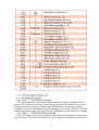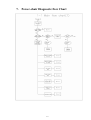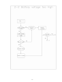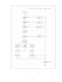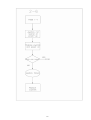
1
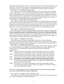
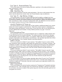
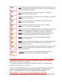
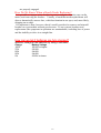
Merits
P3 & P7 series
VR2 Service Manual
Nov.1.2006 V1
P3 & P7 series-VR2 Service manual
Page
Introduction-------------------------------------------------------------------1
1.Service guide---------------------------------------------------------------1
2.Battery-----------------------------------------------------------------------1
2.1 When to replace the batteries-----------------------------------------1
2.2 To remove the batteries------------------------------------------------1
2.3 To install the batteries--------------------------------------------------1
2.4 Check battery charge---------------------------------------------------2
3. Motor, brush and Parking brake-----------------------------------------2
3.1 Motor---------------------------------------------------------------------2
3.2 Brush---------------------------------------------------------------------3
3.3 Parking Brake-----------------------------------------------------------4
4. Electrical illustrated parts breakdown----------------------------------5
5. VR2 Controller------------------------------------------------------------6
5.1 VR2 joystick buttons--------------------------------------------------6
5.2 Control system status indication-------------------------------------8
5.3 Diagnostics ------------------------------------------------------------9
5.4 Trip type and their possible causes----------------------------------11
5.5 Basic tests---------------------------------------------------------------15
6. Power wheelchair troubleshooting-------------------------------------15
(Typical problems and solution)
7. Power-chair diagnostic flow --------------------------------------------19
Introduction
The purpose of this manual is to provide dealers and/or distributors with the
product information and instructions that are required for servicing the P3 &
P7 series VR2 controller powerchair.
1.Service Guide
n
n
n
n
n
n
Batteries
Motor, Brush, and Brake
Electrical illuatrated parts breakdown
PG VR2 controller
Troubleshooting
Fault diagnostic flow chart
WARNING
Before performing any maintenance or service, turn the power off.
NEVER allow tools and/or battery cable(s) to contact BOTH the battery
terminal(s) or the post(s) at the same time. An electrical short may occur
resulting in serious personal injury and/or damage. It is strongly
recommended that battery installation and/or replacement should be
done only by a qualified technician.
2 Batteries
2.1 When to replace the Batteries
The batteries may have to be replaced should one of the following
conditions occurs:
n The Powerchair’s driving distance decreases significantly.
n Incomplete charge.
n The Charging cycle becomes significantly longer or shorter than
before.
2.2 To Remove the Batteries
1. Unplug communication bus of joystick and remove the seat and
shroud.
2. Disconnect the wiring harness from the batteries by removing
the screws.
3. Remove the batteries from the power chair base.
2.3 To install the Batteries
1. Install two new batteries into the power chair base.
2. Connect the wiring harness to the batteries. Refer to“Electrical
illustrated parts breakdown” diagram.
3. Confirm the battery supply voltage. (the battery voltage to the
controller should be at least 25VDC)
4. Cover the shroud and Install the seat then plug the
1
communication bus.
2.4 Checking Battery Charge:
1. Connect the voltmeter negative probe to controller power-.
2. Connect the voltmeter positive probe to controller power+.
3. The voltmeter should measure 23-27 volts (i.e. Battery
Voltage).
4. If the voltage is negative, check for correct battery wiring
polarity. Ensure that batteries are connected correctly.
5. If the voltage reading is zero, check for wiring open circuits or
battery wiring polarity.
6. Charge the batteries completely before driving.
3 Motors, Brush and parking brake
3.1Motor:
The motor may have to be replaced should one of the following
conditions occurs:
n The Powerchair’s driving power decreases significantly.
n Power chair can not move straightly.
n Motor screwed up and fail.(ex: Harness, connector or case
damaged)
The 24V motors are specifically designed for use on power wheel chairs.
The motors incorporate a metal-cased parking brake. The parking brake
assembly and brushes are protected by a metal cover. The motor frame
is integral with the cast aluminum gearbox housing that forms a strong
and compact unit. (P320: with easy-to-operate levers disengage the
brake for manual pushing of the chair.
Connections and Wiring
1. Each motor has four wires of two different sizes that require
connection. Note that the red and blue(or black) wire
connections will affect the motor orientation.
2. Upon completing all wirings the loom must be fastened to the
frame to minimize strain on the connections.
3. Lift the wheels before making the battery connection and check
if the drive system functions correctly.
4. Ensure that the wheelchair’s power system is equipped with a
circuit breaker or fuses.
Testing
Check the motors and control system when the installation is completed.
Note the following points:
The circuit breaker or fuses must be included in the power circuitry.
Lift the wheels off the ground;
2
Do not arc cables to check for power.
Use a multimeter to check the voltage.
Operation of Clutch
When it is desired to manually push the chair, the clutch is easily
disengaged. Simply turn the lever on each gearbox. Labels are available
for indicating the status of the clutch lever.
Maintenance and Servicing
The motor is a low-maintenance-required motor and except for periodic
checkup, requires no further maintenance under normal conditions. The
batteries should be disconnected during any maintenance procedure and
in fact their complete removal from the chair may help access.
Check system regularly.
Check for loose, damaged or corroded connectors and
terminals.
Replace damaged cabling.
Check motor mountings for tightness.
Clean motor and control system components with a
damp cloth.
The cover may be removed to check the brush length.
Warning:
Do not use the motor if there is any indication of damage or if
abnormities such as: damage to the case, grease leakage, abnormal
response as well as excessive backlash or play, noise, heat, smoke
and/or arcing are present.
Ensure that the motor is securely fastened to the frame and the wheel
securely fastened to the motor.
3.2 Motor Brushes
The motor brushes may have to be replaced should one of the
following conditions occurs:
n The Powerchair’s driving power decreases significantly.
n Power chair can not move straightly.
Each motor contains two or four carbon brushes which may require
replacement after operating the powerchair a long period of time. Brush
replacement is a simple operation:
Disconnect the motor.
Remove the end cover to allow access.
Remove the brush.
Check the commutator for excessive wear or unusual
burns or erosion marks.
3
Reverse the above processes to install the new brush,
ensuring that the brush is still able to slide in the brush
guide.
Ensure the springs seat properly on the brush and the
brush wire is placed properly.
Note:
Ensure correct insulation between motor case and motor wires (refer
ISO 7176-14).
Always replace all the brushes in both motors at the same
time.
Run brushes in for several hours in the forward direction.
Ensure that the parking brake is released when operating the
motor. (This reduces brush bounce which causes arcing and in
turn generates RFI and audible noise.)
3.3 Parking Brake:
The parking brake may have to be replaced should one of the
following conditions occurs:
n Poor parking brake holding ability
n Parking brake screwed up and fail.(ex: Harness, connector or
case damaged)
Poor parking brake holding ability indicates the need for replacing the
parking brake assembly.
Disconnect the motor.
Remove the cover to allow access.
Cut/solder the wires of the parking brake. Avoid excess strain
on the wires.
Remove the screws that hold the parking brake assembly
together.
Reverse the process to install the new parking brake
assembly.
Check the armature which must rotate freely with the
parking brake disengaged.
4
4 Electrical illustrated part Breakdown
seatpost(VR2)
seatlift(VR2)
5
rehab seat(VR2)
5 VR2 Controller
.5.1 VR2 Joystick buttons:
6
.. On/Off Button and Battery Gauge
The on/off button applies power to the control system electronics,
which in turn supply power to the wheelchair’s motors. Do not use the
on/off button to stop the wheelchair unless there is an emergency. (If you
do, you may shorten the life of the wheelchair drive components).
The battery gauge shows you that the wheelchair is switched on. It
also indicates the operating status of the wheelchair.
..Locking / Unlocking the Wheelchair
The VR2 control system can be locked to prevent unauthorized use.
The locking method is via a sequence of key presses and joystick
movements, as detailed below.
To lock the wheelchair:
• While the control system is switched on, depress and hold the on/off button.
• After 1 second the control system will beep. Now release the on/off button
• Deflect the joystick forwards until the control system beeps.
• Deflect the joystick in reverse until the control system beeps.
• Release the joystick, there will be a long beep.
• The wheelchair is now locked.
To unlock the wheelchair
• Use the on/off button to switch the control system on. The maximum speed /profile
indicator will be rippling up and down.
• Deflect the joystick forwards until the control system beeps.
• Deflect the joystick in reverse until the control system beeps.
• Release the joystick, there will be a long beep.
• The wheelchair is now unlocked.
..Maximum Speed / Profile Indicator
This is a gauge which shows the maximum speed setting for the
wheelchair. There are five speed settings – step 1 is the lowest speed
and step 5 is the highest speed. This gauge also indicates if the speed of
the wheelchair is being limited or if the control system is locked.
.. Speed / Profile Decrease Button
This button decreases the maximum speed setting or, if the control
system is programmed for drive profile operation, selects a lower drive
profile.
.. Speed / Profile Increase Button
7
This button increases the maximum speed setting or, if the control
system is programmed for drive profile operation, selects a higher drive
profile.
.. Actuator Buttons and LEDs
Depending on whether the wheelchair is fitted with actuator, the
operation is as below.
Depressing either actuator button will enter actuator adjustment mode. This will be
indicated by the illumination of both actuator LEDs. Actuator adjustment can then be
made by deflecting the joystick. To re-enter drive mode, depress either actuator
button.
.5.2.Control System Status indication
The battery gauge and maximum speed /profile indicator show the
status of the control system.
Battery Gauge is Steady
This indicates that all is well.
Battery Gauge Flashes Slowly
The control system is functioning correctly, but you should charge the battery as
soon as possible.
Battery Gauge Steps Up
The wheelchair batteries are being charged. You will not be able to drive the
wheelchair until the charger is disconnected and you have switched the control
system off and on again.
Battery Gauge Flashes Rapidly (even with the joystick released)
The control system safety circuits have operated and the control system has been
prevented from moving the wheelchair. This indicates a system trip, i.e. the VR2 has
detected a problem somewhere in the wheelchair’s electrical system. Please follow
this procedure:
• Switch off the control system.
• Make sure that all connectors on the wheelchair and the control system are mated
securely.
• Check the condition of the battery.
• If you can’t find the problem, try using the self-help guide given in next paragraph.
• Switch on the control system again and try to drive the wheelchair. If the safety
circuits operate again, switch off and do not try to use the wheelchair. Contact your
service agent.
.. Slow or sluggish movement
If the wheelchair does not travel at full speed or does not respond
quickly enough, and the battery condition is good, check the maximum
speed setting. If adjusting the speed setting does not remedy the
problem then there may be a non-hazardous fault. Contact your service
agent
.. Maximum Speed Indication
The number of LEDs illuminated shows the maximum speed setting.
For example, if the setting is speed level 4, then the four left hand LEDs
8
will be illuminated.
… Maximum Speed / Profile Indicator Ripples Up and Down
This indicates the control system is locked.
…Maximum Speed / Profile Indicator Flashes
This indicates the speed of the wheelchair is being limited for safety reasons. The
exact reason will depend on the type of wheelchair,
N
Noottee::
The amount of charge in your batteries depends on a number of
factors, including the way you use your wheelchair, the temperature of
the batteries, their age and the way they are made. These factors will
affect the distance you can travel in your wheelchair. All wheelchair
batteries will gradually lose their capacity as they age. The most
important factor that reduces the life of your batteries is the amount of
charge you take from the batteries before you recharge them. Battery life
is also reduced by the number of times you charge and discharge the
batteries. To make your batteries last longer, do not allow them to
become completely flat. Always recharge your batteries promptly after
they are discharged. If your battery gauge reading seems to fall more
quickly than usual, your batteries may be worn out.
W
Waarrnniinngg
.
.. 5.3 Diagnostics
… Introduction
The primary objective of this section is to assist service personnel in finding the
likely area of a detected fault within the whole wheelchair electrical system. It is
important to realize that even though the control system is signaling a fault, it may not
be the control system itself that is defective. This is because the control system is
able to detect problems in other electrical components (motors, batteries, solenoid
brakes etc.) or, more importantly, the wiring to them. When a control system has
detected a fault a system trip is indicated. Using this guide, it is possible to define a
trip as belonging to one of 10 types. Once this type has been established, there are
suggestions as to what the possible cause may be. The guide should only be used to
decide the starting point of your own diagnosis, as it is possible for the controller to
indicate a fault in another component even though the controller itself may be
defective. Nevertheless, experience has shown that connectors and wiring are the
major cause of wheelchair electrical problems, so it is necessary to examine these
more vulnerable areas first.
… Diagnostics Process
For efficient and effective diagnosis the following basic steps should be taken.
• Establish the type of control system fitted to the wheelchair.
• Confirm there is a trip, or has been an intermittent trip.
• Establish the trip type.
• Refer to the trip table.
• Refer to the possible cause as indicated by the trip table, and carry out
recommended investigative and corrective action.
9
… Detecting a Trip has occurred
Firstly observe the control system’s TruCharge (battery gauge) display. This will
behave as described in one of the followings.
…. Flashing rapidly
The control system is tripped.
• Connecting a programmer to the control system while this is happening will give you
a trip code.
…. Flashing slowly
No trip is currently detected by the control system. The slow flash is an indication
that the batteries require charging.
• A trip may have occurred previously, read the control system’s diagnostic log and
the trip type.
…. Display is steady
No trip is currently detected by the control system.
• A trip may have occurred previously, read the control system’s diagnostic log and
the trip type.
…. Display does not illuminate
No power is reaching the control system.
• Ensure the batteries are fully charged and that all connections between batteries
and the control system are made.
• If these connections are good, then the Power Module may be defective.
… Other Conditions
This covers conditions that are not displayed as trip codes or on the TruCharge
display. This may be because: either the control cannot switch on; the condition is
not considered critical enough to force a trip or the control system cannot detect the
condition.
…. Control system will not switch on
• Check the battery connections to the control system. If these appear to be good,
then the Power Module may be defective.
• Check the cable between the Power Module and the Joystick Module. If this
appears to be good, then either module may be defective.
…. Wheelchair drives slowly
This could be caused by one of the following.
• The control system has been incorrectly programmed.
• A speed limiting function is active, e.g. seat in a raised position on wheelchairs fitted
with lifting seats.
• Defective motor or defective brake.
…. Wheelchair will not drive in a straight line
This could be caused by a defective motor or defective brake.
…. One motor or brake becomes very warm
This could be caused by a defective motor or defective brake.
…. Batteries discharge very quickly
The batteries can discharge very quickly for several reasons, these are described
below.
• Worn or damaged batteries – check battery condition.
• Charger defective or incorrect charger being used – check charger operation (refer
to wheelchair’s operating manual).
• Incorrect batteries being used – refer to wheelchair manufacturer’s instructions for
correct battery types.
• One motor or brake jamming.
10
N
Noottee
TThhee aam
mbbiieenntt tteem
mppeerraattuurree hhaass aa ssiiggnniiffiiccaanntt eeffffeecctt oonn bbaatttteerryy ccaappaacciittyy.. TThheerreeffoorree,, iiff
tthhee tteem
mppeerraattuurree iiss lloow
weerr tthhaann nnoorrm
maall tthhee w
whheeeellcchhaaiirr’’ss rraannggee w
wiilll bbee rreedduucceedd.. IInn tthhiiss
ssiittuuaattiioonn,, tthhee TTrruuC
h
a
r
g
e
b
a
t
t
e
r
y
g
a
u
g
e
s
t
i
l
l
g
i
v
e
s
a
n
a
c
c
u
r
a
t
e
Charge battery gauge sti l gives an accurate ssttaattee ooff cchhaarrggee
rreeaaddiinngg..
… Trip Diagnosis
There are two methods of trip diagnosis.
…. Trip diagnosis with the TruCharge
The TruCharge can illustrated Flash Codes.
…. Using a programmer to read the trip code
If you connect a programmer while the TruCharge display is flashing rapidly, then a
four digit trip code will be displayed. The trip code can be referred to the trip types
using the following table.
5.4 Trip Types and Their Possible Causes
Once the trip type has been established, refer to the relevant section
below for further information.
11
.. Trip Type 1 - Low Battery Voltage
This occurs when the control system detects that the battery voltage has fallen
below 16V. Check the condition of the batteries and the connections to the control
system. If the trip is still present after the batteries and connections have been
checked, then the Power Module may be defective. In the case of 2C02 the Control
System is making a log of the times that the Low Battery Lockout has been initiated.
.. Trip Type 2 – Left Motor Disconnected
This occurs when the control system detects that the left hand motor has become
disconnected. Check the left hand motor, motor connectors and wiring. If the trip is
12
still present after the above checks have been made, then the Power Module may be
defective. The VR2 control system may be programmed to exchange the left and
right motor outputs. In this instance, this section will refer to the left hand motor.
.. Trip Type 3 – Left Motor Wiring Trip
This occurs when the control system detects a fault in the wiring to the left hand
motor, in particular if a motor connection has short-circuited to a battery connection.
Check the left hand motor connectors and wiring. If the trip is still present after the
above checks have been made, then the Power Module may be defective. The VR2
control system may be programmed to exchange the left and right motor outputs. In
this instance, this section will refer to the left hand motor.
.. Trip Type 4 – Right Motor Disconnected
This occurs when the control system detects that the right hand motor has become
disconnected. Check the right hand motor, motor connectors and wiring. If the trip is
still present after the above checks have been made, then the Power Module may be
defective. The VR2 control system may be programmed to exchange the left and
right motor outputs. In this instance, this section will refer to the left hand motor.
.. Trip Type 5 - Right Motor Wiring Trip
This occurs when the control system detects a fault in the wiring to the right hand
motor, in particular if a motor connection has short-circuited to a battery connection.
Check the right hand motor connectors and wiring. If the trip is still present after the
above checks have been made, then the Power Module may be defective. The VR2
control system may be programmed to exchange the left and right motor outputs. In
this instance, this section will refer to the left hand motor.
.. Trip Type 6 – Charger Connected
This occurs when the control system detects that an off-board charger is
connected. Check that the battery charger is disconnected. If the trip is still present
after the charger has been disconnected then the Joystick Module may be defective.
..Trip Type 7 – Possible Joystick Trip
This occurs if the control system detects a problem within its own joystick, or there
is a communications error between the Joystick Module and Power Module. The
joystick can only be replaced by a person authorized by the wheelchair
manufacturer.
7100
Loss of comms to the joystick, check the joystick cable and, if you have
authorization the joystick ribbon cable, connections and mating sockets.
7101
Loss of comms to the joystick, check the joystick cable and, if you have
authorization the joystick ribbon cable, connections and mating sockets.
7102
Loss of power to the joystick, check the joystick cable and, if you have
authorization the joystick ribbon cable, connections and mating sockets.
7103
Internal trip, if you have authorization check the joystick ribbon cable,
connections and mating sockets. Ensure the cable is connected correctly to
both the joystick and the PCB.
7104
Internal trip, if you have authorization check the joystick ribbon cable,
connections and mating sockets. Ensure the cable is connected correctly to
both the joystick and the PCB.
If the trip is still present after the appropriate checks have been made
then the Joystick Module may be defective.
.. Trip Type 8 - Possible Control System Trip
This occurs if the control system detects a problem within itself. The control system
can only be repaired by an authorized person.
13
.. Trip Type 9 - Solenoid Brake Trip
This occurs when the control system detects a problem in the solenoid brakes or
the connections to them.
1505 - Left Brake Trip
1506 - Right Brake Trip
Check these connections and the solenoid brakes. If the trip is still present after the
above checks have been made, then the Power Module may be defective.
.. Trip Type 10 - High Battery Voltage
This occurs when the control system detects that the battery voltage has risen
above 35V.The most common reasons for this are overcharging of the battery or bad
connections between the control system and the batteries. Check the batteries and
the connections to them. If the trip is still present after the batteries and connections
have been checked, then the Power Module may be defective.
.. Joystick Displaced at Power-up
The most common cause of this trip is if the joystick is deflected away from center
before the control system is switched on. When the control system is switched on,
the battery gauge will blink for a short time. Check that the user is not deflecting the
joystick before the blink finishes. If the problem persists, trip type 7 must be
assumed.
.. Communications Error
The most likely cause of a communications error is a defective cable between the
Power Module and the Joystick Module. The cable should be checked for damage,
and replaced if found to have a fault. The Joystick Cable can only be replaced by a
person authorized by the wheelchair manufacturer, if the problem persists then either
the Power Module or the Joystick Module could be defective.
.. Inhibit 2 Active
This occurs when the Inhibit 2 input is active. The Inhibit 2 input is via the INH-2
way connector and is normally associated with speed limit or actuator functions. The
operation of Inhibit 2 will depend upon the programmed settings and the wheelchair
on which it is being used. Check all wiring and switches connected to Inhibit 2. If
these appear to be in working order, then the Power Module may be defective.
.. Inhibit 3 Active
This occurs when the Inhibit 3 input is active. The Inhibit 3 input is via the 3 way
onboard charger (OBC) and is normally associated with this function. The operation
of Inhibit 3 will depend upon the programmed settings and the wheelchair on which it
is being used. Check all wiring, switches and OBC (if fitted) connected to Inhibit 3. If
these appear to be in working order, then the Power Module may be defective.
.. Current Limit Active
This occurs when the control system operates above the Current Limit Threshold
for a period of time greater than the Current Limit Time. This has been designed to
notify the Healthcare Technician that the control system has operated outside of its
programmed range.
.. High Temperature
This occurs when the control system reaches its Temperature Threshold and thus
becomes too hot. The controller goes out of drive into standby to allow the controller
to cool down. An entry is made in the system log each time the controller gets too hot
and goes out of drive.
14
.5.5 Basic Tests
After a repair has been completed, the following tests should be carried
out. These are minimum recommendations, depending on the nature of
the original trip then additional tests may be required.
.. General Inspection
Make sure all connectors are securely mated.
• Check the condition of all cables and connectors for damage.
• Make sure that all components of the control system are securely mounted.
• Do not overtighten any securing screws.
.. Brake Test
These tests should be carried out on a level floor with at least one meter clear
space around the wheelchair.
• Switch on the control system.
• Check the TruCharge display remains on, or flashes slowly, after one second.
• Push the joystick slowly forwards until you hear the parking brakes operate. The
wheelchair may start to move.
• Immediately release the joystick. You must be able to hear each parking brake
operate within 2 seconds.
• Repeat the test a further three times, pushing the joystick slowly backwards, left
and right.
.. Drive Test
With the maximum speed control in the minimum position, drive the wheelchair in
all directions, ensuring the drive is comfortable and easy to control for the user.
Repeat the above but with the speed control set to maximum.
.. Gradient Test
Before carrying out this test ensure another person is present to prevent the
wheelchair from tipping backwards.
Drive the wheelchair forwards up its maximum rated gradient. While on the gradient
release the joystick and ensure the wheelchair comes to rest and the brakes are applied
without the front wheels lifting of the ground. Deflect the joystick forwards and continue
driving up the slope. Ensure the pick up is smooth and positive. Stop the wheelchair and
reverse down the gradient. While on the gradient release the joystick and ensure the
wheelchair comes to rest and the brakes are applied without the front wheels lifting of the
ground.
6. Power wheelchair Troubleshooting
Typical problems & solutions:
*Batteries won't Charge or Charger isn't Working
1. Ensure that the charger is properly plugged into the wall outlet, and that the
outlet has power (the power cord may have come unplugged, or an outlet may
be connected to a switch that was unintentionally turned off, or the outlet
tripped a breaker in the house's electrical panel).
2. If the charger is off-board of the powerchair, confirm that the power switch
is on.
3. Confirm that the charger is properly plugged into the powerchair.
4. Confirm that fuse of the charger is not burn out.
5. Observe the charger's lights or ammeter to confirm that the charger is
15
operating
*Powerchair Suddenly Runs Dramatically Slower than Usual
1. If the powerchair has a tilt, or lifting seat, confirm that the seat is in the lowest
position (power seating functions use an inhibit to reduce a powerchair's speed for
safety when tilted or lifted, so if the seat is slightly tilted or lifted, the inhibit will
slow the powerchair until the seat is returned to the lowest position).
2. If outdoors, confirm that you're not in exceptionally hot temperatures, or in
aggressive terrain, causing the powerchair to overheat and enter thermal fold back
or thermal protection, which reduces the power to protect the powerchair's
electronics from excessive heat. Allow the powerchair to cool, and move to less
aggressive terrain and cooler conditions as soon as possible, which will restore full
power.
*Powerchair Suddenly Looses Power and Shows a Drained Battery
Gauge, but then Returns Quickly to Full Power and a Full Charge
Level.
1. Check to make sure that the battery connection plugs and terminal connections
are secure.
*Powerchair moves downward slightly when stop on a slope.
1. Lining of the magnetic brake may have worn out, replace the magnetic brake.
*Joystick Flashes an Error Code
1. Turn joystick power off, then on again to see if the code remains (a deflected
joystick at start up or sleep mode can cause this symptom, which re-powering will
resolve).
2. If the motors have brake levers ,confirm that the levers are properly engaged,
then turn the powerchair off, then on again to see if the code remains .
3. Check all connection plugs, including the joystick, motor, and battery plugs,
confirming that all is secure, then turn the powerchair off, then on again to see if
error code remains.
4. If error code still remains, see following flash-code diagnostic to resolve the
problem.
If a system trip occurs, you can find out what has happened by counting the number
of bars on the battery gauge that are flashing.
Below is a list of self-help actions. Go to the number in the list which matches the
number of flashing bars and follow the instructions.
* If the programmable parameter, Motor Swap has been enabled, then left and right
hand references in this table will need transposing.
16
1 bar:The battery needs charging or there is a bad connection to the
battery. Check the connections to the battery. If the connections are
good, try charging the battery.
2 bar:The left hand motor* has a bad connection. Check the
connections to the left hand motor.
3 bar:The left hand motor* has a short circuit to a battery connection.
Contact your service agent.
4 bar:The right hand motor* has a bad connection. Check the
connections to the right hand .
5 bar:The right hand motor* has a short circuit to a battery
connection. Contact your service agent.
6 bar:The wheelchair is being prevented from driving by an external
signal. The exact cause will depend on the type of wheelchair
you have, one possibility is the battery charger is connected.
7 bar:A joystick fault is indicated. Make sure that the joystick is in
the center position before switching on the control system.
8 bar:A control system fault is indicated. Make sure that all
connections are secure.
9 bar:The parking brakes have a bad connection. Check the parking
brake and motor connections. Make sure the control system
connections are secure.
10 bar: An excessive voltage has been applied to the control system.
This is usually caused by a poor battery connection. Check the
battery connections.
7 bar+S: A communication fault is indicated. Make sure that
joystick cable is securely connected and not damaged.
Joystick Illuminates but Does Not Respond to Joystick Movement*
1. Disconnect the joystick's connection plug, then reconnect it, powering up
joystick to see if the issue is resolved.
2. Disconnect the battery connection plugs, then reconnect, powering up the
joystick to see if the issue is resolved.
*This is an extraordinary occurrence, and even though resetting the power may
resolve the issue in the immediate. If this happens again, the powerchair's
joystick ,communication bus or power module may have problems.
Motors Make a Vibrating, Clicking Sound when Driving
1. Disengage, then reengage the free-wheel release levers, confirming that they
17
are properly engaged.
How Do We Know When a Brush Needs Replacing?
It is possible to inspect motor brushes by unscrewing the retention caps on the
motor, and removing the brushes. Visually, a brush that needs replacement will
show a dramatically uneven face, with discoloration in one spot, and, more likely,
chipping on an edge.
It's important to note, however, that it's usually not ideal to remove and reinstall
brushes on a powerchair without good reason. If one or more brushes need
replacement ,the symptoms in operation are unmistakable, including loss of power
and the inability to drive in a straight line.
How can we tell if batteries are fully charged?
Measure voltage of the batteries by using a voltmeter.
Charge
100%
75%
50%
25%
0%
Battery Voltage
25.60V or higher
25.20V
24.60V
24.00V
23.60V or lower
18
7.
Power-chair Diagnostic flow Chart
19
20
21
22
23
24
25
26
27