1
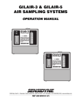
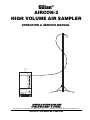
Gilian®
AIRCON-2
HIGH VOLUME AIR SAMPLER
OPERATION & SERVICE MANUAL
SINGLE MODE HOLD PROGRAMMING RUN
DELAY TIME
RUN TIME
HOLD TIME
#CYCLES
PRESSURE
CYCLE MODE LOW BATTERY
ACCEPT
PROG
FAULT ERROR
TIME
RUN
PRESS.
HOLD
16333 Bay Vista Dr. • Clearwater, FL 33760 • (800) 451-9444 • (727) 530-3602 • (727) 539-0550 [FAX] * www.sensidyne.com
Revision D • Document No. F-PRO-3100
LETTER FROM THE PRESIDENT
Thank you for purchasing your new Sensidyne air monitoring product. We stand
behind all of the products we sell . . . each Sensidyne product has been designed
and manufactured to provide unparalleled service, day after day. Our professional
staff has tested each unit under the strictest conditions possible to ensure successful,
accurate results every time. With the minimal care and maintenance described in this
Operation & Service Manual, the Sensidyne product you have purchased will give
you many years of reliable service.
Our only goal is that you are pleased with the quality, performance, and
accuracy of your Sensidyne product. Be assured of our complete and prompt
answers to any questions you may have about this product, since we are totally
committed to providing you with fast, responsive customer service and technical
support.
If you ever have difficulty solving a problem with any Sensidyne product, or if you
are not 100% satisfied with the service you receive from any level of our organization, please let me know about it. Call me at either of the numbers listed below, and
I will personally research your problem to ensure that it is resolved in a manner that
is satisfactory to you. Your satisfaction with our products and service is of the utmost
importance to me.
Sincerely,
Carl Mazzuca
President, Sensidyne, Inc.
800-451-9444
727-530-3602
Fax: 727-539-0550
Gilian® AIRCON-2 HIGH VOLUME AIR SAMPLER
PROPRIETARY NOTICE
This manual was prepared by Sensidyne, Inc. exclusively for the owner of the AirCon-2 High Volume Air Sampler. The
material within this manual is the proprietary information of Sensidyne, Inc. and is to be used only to understand, operate,
and service the instrument. By receiving this document, the recipient agrees that neither this document nor the information
disclosed within nor any part shall be reproduced or transferred, physically, electronically or in any form or used or disclosed to others for manufacturing or for any other purpose except as specifically authorized in writing by Sensidyne, Inc.
COPYRIGHT NOTICE
© 1998, Sensidyne, Inc. ALL RIGHTS RESERVED. Information contained in this document is protected by copyright. No part
of this document may be photocopied, reproduced, or translated to another program or system without prior written
authorization from Sensidyne, Inc.
TRADEMARK NOTICE
Sensidyne, the Sensidyne logo, Gilian, and the Gilian logo are registered trademarks of Sensidyne, Inc. These trademarks
are protected through use and registration in the United States. The trademarks and servicemarks used in this document are
the property of their respective companies and are used only for informational and explanatory purposes.
DISCLAIMER
THE SELLER ASSUMES NO RESPONSIBILITY WHATSOEVER, TO ANY PARTY WHOSOEVER, FOR ANY
PROPERTY DAMAGE, PERSONAL INJURY, OR DEATH RECEIVED BY OR RESULTING FROM, IN
WHOLE, OR IN PART, THE IMPROPER USE, INSTALLATION, OR STORAGE OF THIS PRODUCT BY THE
USER, PERSON, FIRM, ENTITY, CORPORATION OR PARTY NOT ADHERING TO THE INSTRUCTIONS
AND WARNINGS IN THIS MANUAL, OR OTHERWISE PROVIDED BY THE SELLER OR FROM NOT ADHERING TO ALL FEDERAL, STATE, AND LOCAL ENVIRONMENTAL AND OCCUPATIONAL HEALTH AND
SAFETY LAWS AND REGULATIONS.
THE SELLER SHALL NOT BE LIABLE FOR DIRECT, INDIRECT, CONSEQUENTIAL, INCIDENTAL OR
OTHER DAMAGES RESULTING FROM THE SALE AND USE OF ANY GOODS AND SELLERS’ LIABILITY
HEREUNDER SHALL BE LIMITED TO REPAIR OR REPLACEMENT OF ANY GOODS FOUND DEFECTIVE.
THIS WARRANTY IS IN LIEU OF ALL OTHER WARRANTIES, EXPRESSED OR IMPLIED, INCLUDING BUT
NOT LIMITED TO THE IMPLIED WARRANTIES OF MERCHANTABILITY AND FITNESS FOR USE OR FOR
A PARTICULAR PURPOSE WHICH ARE EXPRESSLY DISCLAIMED.
Sensidyne Document No. F-PRO-3100 (Rev D)
3
Gilian® AIRCON-2 HIGH VOLUME AIR SAMPLER
TABLE OF
CONTENTS
• PREFACE
• WARNINGS ........................................................................................................................... 7
• Packing List .......................................................................................................................... 8
SECTION ONE: INTRODUCTION
1.1
Description ................................................................................................................. 9
1.2
Power Sources ........................................................................................................... 10
1.2.1
1.2.2
1.2.3
1.2.4
1.3
Controls & Indicators .............................................................................................. 12
1.3.1
1.3.2
1.3.3
1.3.4
1.4
AC Power ....................................................................................................... 10
Voltage ........................................................................................................... 10
DC Power ....................................................................................................... 10
Power Module ................................................................................................ 10
On/Off Switch ................................................................................................ 12
Flow Adjustment ............................................................................................ 12
LCD Display (Program Model) ...................................................................... 12
Touch-Pad Buttons (Program Model) ........................................................... 12
Standard Parts ........................................................................................................... 12
1.4.1
1.4.2
Telescopic Sampling Mast ............................................................................. 12
Air House & Hose Support Tip ...................................................................... 12
SECTION TWO: SET-UP
2.1
General Set-Up .......................................................................................................... 16
2.1.1
2.1.2
2.1.3
2.2
Charging ..................................................................................................................... 17
2.2.1
2.2.2
4
Sampling Mast ................................................................................................ 16
Air Hose ......................................................................................................... 16
Filter Cassettes ............................................................................................... 16
Using The DC Unit ......................................................................................... 17
Charging With The Power module................................................................ 17
— PRELIMINARY —
Sensidyne Document No. F-PRO-3100 (Rev D)
Gilian® AIRCON-2 HIGH VOLUME AIR SAMPLER
TABLE OF
CONTENTS
SECTION THREE: OPERATION
3.1
Overview .................................................................................................................... 21
3.1.1
3.1.2
3.1.3
3.2
Basic Operation ........................................................................................................ 21
3.2.1
3.2.2
3.3
Single Mode (All Models) .............................................................................. 21
Cycle Mode Operation ................................................................................... 21
Faults ........................................................................................................................... 24
3.3.1
3.3.2
3.3.3
3.4
AC Basic Model .............................................................................................. 21
AC Program Model ........................................................................................ 21
DC Program Model ........................................................................................ 21
Fault Function (Program Model) ................................................................... 24
Correcting Fault Conditions ........................................................................... 24
Low Battery Indication (DC Model) .............................................................. 24
Programming Examples ......................................................................................... 25
3.4.1
3.4.2
Cycle Mode Programming Example .............................................................. 25
Other Programming Examples ...................................................................... 25
SECTION FOUR: AFTER SAMPLING
4.1
Unit Shut Down ........................................................................................................ 32
4.2
Sampling Mast ........................................................................................................... 32
4.3
Battery Pack Maintenance ...................................................................................... 32
Sensidyne Document No. F-PRO-3100 (Rev D)
5
Gilian® AIRCON-2 HIGH VOLUME AIR SAMPLER
TABLE OF
CONTENTS
SECTION FIVE: APPENDICES
• Appendix A: Parts List ..................................................................................................... 33
• Appendix B: Specifications ............................................................................................. 34
• Appendix C: Returned Material Authorization ........................................................... 35
• Returned Material Authorization ............................................................................. 35
• Service Options ....................................................................................................... 35
LIST OF FIGURES
1.1
1.2
1.3
1.4
2.1
2.2
2.3
3.1
AirCon-2 Air Sampler with Sampling Mast & Air Hose ........................................... 11
Front Panel (Program Model) .................................................................................. 13
Liquid Crystal Display (Program Model) ................................................................. 14
AirCon-2 Accessory Configurations ......................................................................... 15
DC Sampler Set-Up .................................................................................................. 18
Power Module Set-Up (Single Pack) ....................................................................... 19
Power Module Set-Up (Multiple Packs) .................................................................. 20
Cycle Mode Programming Example ........................................................................ 25
LIST OF TABLES
1.1
3.1
3.2
3.3
3.4
3.5
3.6
3.7
3.8
6
Available AirCon-2 Models ........................................................................................9
Setting Air Flow (Basic & Program Models) ............................................................ 22
Single-Mode Operation ............................................................................................ 23
Pre-Programmed Data .............................................................................................. 26
Entering Program Mode ........................................................................................... 27
Delay Time ............................................................................................................... 28
Run Time ................................................................................................................. 29
Hold Time ................................................................................................................ 30
Run Cycles ................................................................................................................ 31
— PRELIMINARY —
Sensidyne Document No. F-PRO-3100 (Rev D)
Gilian® AIRCON-2 HIGH VOLUME AIR SAMPLER
WARNINGS !
READ AND UNDERSTAND ALL WARNINGS BEFORE USE
Read and understand ALL warnings before using this product. Failure to read, understand, and comply with
ALL warnings could result in property damage, severe personal injury, or death.
Read and understand ALL applicable Federal, State, and Local environmental health and safety laws and
regulations, including OSHA. Ensure complete compliance with ALL applicable laws and regulations before
and during use of this product.
UNDER NO CIRCUMSTANCES should this product be used except by qualified, trained, technically
competent personnel and not until the warnings, Operation and Service Manual, labels, and other literature
accompanying this product have been read and understood.
The Operation and Service Manual must be read and understood by each user before operating this product
or using its accessories, in order to ensure proper and safe use and installation of this product and to ensure
familiarity with the proper treatment and safety procedures in the event of an accident.
Caution: Risk of electrical shock.
Warning: Line cord must be removed to remove all power from equipment.
DO NOT remove, cover, or alter any label or tag on this product, its accessories, or related products.
DO NOT operate this product should it malfunction or require repair. Operation of a malfunctioning product,
or a product requiring repair may result in serious personal injury or death. DO NOT attempt to repair or
modify the instrument, except as specified in the Operation and Service Manual. Contact the Sensidyne
Service Department to arrange for a Returned Material Authorization (RMA).
Use ONLY genuine Sensidyne® replacement parts when performing any maintenance procedures described
in this manual Specifically the DC version of the AirCon-2 is designed for use with AirCon-2 battery packs,
and should not be used in conjunction with any other equipment. Rechargeable battery packs are designed
to be charged with the AirCon-2 Power Module and in strict accordance with the charging instructions
contained in this manual. Failure to follow these warnings may seriously impair instrument performance.
Repair or alteration of the product beyond the scope of these maintenance instructions, or by anyone other
than a certified Sensidyne® serviceman, could cause the product to fail to perform as designed, and persons
who rely on this product for their safety could sustain severe personal injury or death.
DO NOT operate unit in excessive chemical or water vapor atmospheres. Failure to follow instructions may
cause permanent damage to the equipment.
NEVER block the cooling air inlets (located at the top/back of unit) when the unit is operating.
NEVER block any of the venting holes (located on the sides of the case) when the unit is operating.
ALWAYS place the unit on a secure and level surface when operating.
ALWAYS operate unit within the intrinsically safe environmental regime specified (non-hazardous locations).
Sensidyne Document No. F-PRO-3100 (Rev D)
7
Gilian® AIRCON-2 HIGH VOLUME AIR SAMPLER
PACKING LIST
The items listed below are shipped with the Gilian AirCon-2 High Volume Air Sampler:
•
AirCon-2 Air Sampler unit
AirCon-2 “AC” models include a Power Cord
AirCon-2 “DC” models require a battery pack (sold separately)
•
Air Hose (Tubing)
•
Hose Support Tip
•
Sampling Mast
•
Operation and Service Manual
•
Registration Card/Warranty Card
ALWAYS check to make certain
you have received all of the items listed above.
If you have any questions or need assistance,
contact your Sales Representative, or call
(800) 451-9444
OR
(727) 530-3602
8
— PRELIMINARY —
Sensidyne Document No. F-PRO-3100 (Rev D)
Gilian® AIRCON-2 HIGH VOLUME AIR SAMPLER
SECTION ONE
INTRODUCTION
1.1
DESCRIPTION
IMPORTANT
You must read this manual in its entirety to ensure proper
operation of your unit.
The AirCon-2 Air Sampling System is a powerful environmental air sampler used to collect air samples indoors and outdoors. It is equipped with useful performance features industrial hygienists need most; easy
set-up, compact size, battery pack operation, programmable timing functions and DC portability.
Table 1.1 (below) lists the available AirCon-2 models.
The AirCon-2 high volume air sampling system consists
of a positive displacement pump with a unique patented regulator system which maintains flow constant
over a flow range of 2-30 LPM. The sampler maintains
air flow constant for sampling of airborne particulate,
hazardous dust and low concentration pollutants using
many popular filter cassettes. The volume of air that
passes through the filter cassette is determined by the
following:
Air flow x Elapsed time = Volume
The unit is set up in the required location and
plugged into a properly grounded voltage source.
DC version units are connected to either a 2-hour or
4-hour battery pack and/or to a power module which
is designed to power DC version units from a standard AC source.
The AirCon-2 system provides a telescopic sampling
mast which is extended and to which the air hose/
support tip is connected. The media, typically a filter
cassette, is inserted into the end of the sampling
hose. The other end of the air hose is connected to
the “Air Inlet” located at the front of the sampler.
After positioning the unit and setting up the sampling
mast stand, the unit can be turned on. Air flow is set
by use of the external flow adjust knob and is indicated on the built-in rotameter.
Programmable models offer a touch keypad and LCD
display which allow the user to program sampling
routines. Programmable timing functions include:
start and stop times, intermittent run, delay, run/hold
and memory storage of up to three custom timing
programs. The full-function display and touch pad
offer key-in programming and visual monitoring of
all timing functions during programming and sampler
operation.
Part No.
Voltage/Model Type §
801010-1
AC Basic - 115 VAC
801010-2
AC Basic - 230 VAC
801011-1
AC Program - 115 VAC
X
X
801011-2
AC Program - 230 VAC
X
X
801012
AC Power
DC Power
Timing
X
DC Program **
X
X
Notes:
§ All kits include: main sampler unit, air hose, hose support tip, sampling mast, and manual.
AC kits also include an AC line cord.
** DC kits require 2-hour or 4-hour battery pack and/or Power Module for operation.
DC items sold separately.
† DC units can operate on AC current when used with optional Power Module.
Table 1.1
Available Aircon-2 Models
Sensidyne Document No. F-PRO-3100 (Rev D)
9
Gilian® AIRCON-2 HIGH VOLUME AIR SAMPLER
1.2
POWER SOURCES
1.2.1
AC Power
1.3.3
AC power is provided by means of a removable line
cord which plugs into a 3-prong power jack located on
the back of the unit. A 2-prong Euro plug is provided
for 230 VAC operation.
1.2.2
Voltage
The AirCon-2 operating voltage is preset at the factory
for either 115 or 230 volts. This is indicated on the label
located at the rear of the unit. If you need to change
the voltage, do the following:
WARNING
Make certain you unplug the unit before proceeding.
1.
Remove the screws holding the cover
2.
Facing the left side of the unit as viewed from the
front, locate the voltage select switch which is approximately 1/3 of the way up from the bottom of
the PC board.
3.
To change the voltage, insert a small flat blade
screwdriver into the slot and rotate to the appropriate voltage.
4.
Remove the existing fuse and replace with the appropriate fuse for that voltage.
5.
Replace the cover and provide the proper line cord
adapter for the voltage receptacle.
DC Power
DC Power is provided by two-hour and four-hour battery packs. The battery packs can be stacked and interconnected to achieve the ampere hour rating required
to meet the most stringent sampling conditions. Battery
packs are recharged with the optional Power Module.
1.2.4
Power Module
The DC version of the AirCon-2 can be run directly off
the power module. If the battery module is also attached, it will slowly charge the battery while still providing sufficient power to run the sampler. It will rapidly charge the battery if the sampler is turned off under the same circumstances. The power module may
also be used as a stand-alone battery charger and may
charge one or more batteries. The unit will automatically reduce the charging currents as the battery becomes fully charged. An LED indicator illuminates
when charging and flashes when charging is complete.
If no battery is attached it will flash indicating sufficient
voltage to run the sampler. The power module can operate on 115–230 VAC, 47–63 Hz.
IMPORTANT
You should place a label or sticker on the unit to show that the
voltage has been changed.
NOTE
Changing factory-set 115 VAC units to 230 VAC
negates CE certification.
10
— PRELIMINARY —
Sensidyne Document No. F-PRO-3100 (Rev D)
Gilian® AIRCON-2 HIGH VOLUME AIR SAMPLER
21
22
20
1.
2.
3.
4.
5.
6.
7.
8.
9.
10.
11.
12.
Enclosure
Handle
Mounting Feet (4)
Cooling Air Inlet
Cooling Air Discharge
Discharge Air Boss
AC Power Inlet
DC Supply Latch **
DC Interconnect Plug **
On/Off Switch
LCD Display †
ACCEPT Key †
13. PROGRAM Key †
14. TIME/PRESS. Key †
15. RUN/HOLD Key †
16. Inlet Air Boss Suction
17. Flow Adjust Knob
18. Flowmeter
19. Sampling Mast
20. Air Hose
21. Hose Support
22. Sampling Media (ref only)
** DC Units only
† Program Models only
2
2
19
4
16
6
18
7
17
SINGLE MODE HOLD PROGRAMMING RUN
5
DELAY TIME
RUN TIME
HOLD TIME
#CYCLES
PRESSURE
11
CYCLE MODE LOW BATTERY
ACCEPT
PROG
FAULT ERROR
TIME
RUN
PRESS.
HOLD
8
12
5
15
1
13
3
9
14
10
Figure 1.1
AirCon-2 Air Sampler with Sampling Mast & Air Hose
Sensidyne Document No. F-PRO-3100 (Rev D)
11
Gilian® AIRCON-2 HIGH VOLUME AIR SAMPLER
1.3
CONTROLS & INDICATORS
1.3.1
On/Off Switch
1.4.1
The power is activated by a rocker switch located to
the right of the key pad. The removable electrical cord
provided is attached at the back of the unit marked “Input Power.”
CAUTION
Flow Adjustment
The patented flow controller system consists of the flow
control regulator located in the base of the pump, and
the flow control system which consists of the flow adjust valve and rotameter located on the front of the
sampler.
1.3.3
STANDARD PARTS
Telescopic Sampling Mast
The telescopic sampling mast is provided as an independent stand to isolate the filter cassette from the unit
insuring vibration-free sampling. The mast can be extended to achieve any height up to approximately 5
feet and collapses for convenient storage.
1.4.2
Line cord must be removed to remove all power from equipment.
1.3.2
1.4
Air Hose & Hose Support Tip
Approximately 6 feet of hosing is supplied with the
unit. One end is connected to the Inlet Air Boss Suction
port on the sampler and threaded through the Hose
Support Tip which is mounted on the sampling mast. A
filter cassette is then attached to the other end of the air
hose.
LCD Display (Program Model)
A large easy-to-read display is included on Program
Models (see Figures 1.2 & 1.3). The display includes direct digital readings, as well as a variety of messages
pertaining to the operation and programming of the
unit.
1.3.4
Touch-Pad Buttons (Program Model)
The Touch-Pad buttons are explained as follows:
ACCEPT
This is used to switch the unit into the preprogrammed cycle modes or as confirmation (in programming mode) to accept data into memory.
PROG (Program)
This button is used to enter programming mode
and to set or change program data.
TIME/PRESS. (Pressure)
Pressing this button toggles the display between
Time and Pressures readings. These readings can
be viewed any time while the unit is running.
RUN/HOLD
Pressing this button switches the pump operation
between Run and Hold functions.
12
— PRELIMINARY —
Sensidyne Document No. F-PRO-3100 (Rev D)
Gilian® AIRCON-2 HIGH VOLUME AIR SAMPLER
A irCon2
High Volume Air Sampler
SINGLE MODE HOLD PROGRAMMING RUN
DELAY TIME
RUN TIME
HOLD TIME
#CYCLES
PRESSURE
ON
CYCLE MODE LOW BATTERY
FAULT ERROR
OFF
ACCEPT
PROG
I
TIME
RUN
PRESS.
HOLD
Gilian®
O
Made in USA
Figure 1.2
Front Panel (Program Model)
Sensidyne Document No. F-PRO-3100 (Rev D)
13
Gilian® AIRCON-2 HIGH VOLUME AIR SAMPLER
SINGLE MODE HOLD PROGRAMMING RUN
DELAY TIME
RUN TIME
HOLD TIME
#CYCLES
PRESSURE
CYCLE MODE LOW BATTERY
FAULT ERROR
Figure 1.3
Liquid Crystal display (Program Model)
14
— PRELIMINARY —
Sensidyne Document No. F-PRO-3100 (Rev D)
Gilian® AIRCON-2 HIGH VOLUME AIR SAMPLER
Aircon-2
Sampler
SINGLE MODE HOLD PROGRAMMING RUN
DELAY TIME
RUN TIME
HOLD TIME
#CYCLES
PRESSURE
CYCLE MODE LOW BATTERY
Aircon-2
Sampler
ACCEPT
PROG
FAULT ERROR
TIME
RUN
PRESS.
HOLD
SINGLE MODE HOLD PROGRAMMING RUN
DELAY TIME
RUN TIME
HOLD TIME
#CYCLES
PRESSURE
CYCLE MODE LOW BATTERY
Battery
Pack
ACCEPT
PROG
FAULT ERROR
TIME
RUN
PRESS.
HOLD
Battery
Pack
Battery
Pack
Power
Module
Power
Module
4-Hour Battery Pack
mounted on the Power
Module for charging.
DC Sampler mounted onto
a 4-Hour Battery Pack.
DC Sampler and 4-Hour
Battery Pack mounted on
the Power Module for
operation in AC or DC
environments.
Figure 1.4
AirCon-2 Accessory Configurations
Sensidyne Document No. F-PRO-3100 (Rev D)
15
Gilian® AIRCON-2 HIGH VOLUME AIR SAMPLER
SECTION TWO
SET-UP
2.1
GENERAL SET-UP
Place the unit in the desired sampling area. Make certain the unit is standing in a vertical position.
NOTE
When using rotameters, it is important to maintain a vertical
position for optimum accuracy. The rotameter provided in this
sampler has been tested for accuracy and is within ± 5% of full
scale.
2.1.1
2.1.2
Air Hose
To attach the Air Hose, perform the following steps:
1) Connect one end of the flexible tubing to the air inlet valve located at the front of the sampler.
2) Connect the hose support tip to the top of the extended sampling mast.
3) Insert tubing through the hose support tip, with 2–
3" of the hosing extending out.
Sampling Mast
To set up the Sampling Mast, perform the following
steps:
1) First, unfold the legs at the bottom of the mast
stand by opening the locking knob and pulling the
legs outwards as far as they will extend.
2) Loosen the largest locking collar at the bottom of
the stand and pull out by the second largest locking collar. Tighten the largest collar.
3) Holding the extended section, loosen the second
largest locking collar and extend the next section
of the mast. Tighten the second largest collar.
4) Repeat this procedure until the mast is extended to
its full or required height.
4) Insert filter cassette or other media into air hose
end.
2.1.3
Filter Cassettes
To install the Filter Cassette, do the following:
1) First, remove any cap plugs from the filter cassette.
These may be colored in red and blue. Also remove the end of the filter cassette to expose the filter. This is called “open-face” filter sampling. This
allows air to enter the cassette freely with minimal
back pressure.
2) Plug the filter cassette into the end of the sampling
hose.
5) Be sure to tighten each locking collar before proceeding to loosen the next. Position the extended
mast next to sampler.
16
— PRELIMINARY —
Sensidyne Document No. F-PRO-3100 (Rev D)
Gilian® AIRCON-2 HIGH VOLUME AIR SAMPLER
2.2
CHARGING
2.2.1
Using The DC Unit
Connecting the DC Unit
1) Place the battery pack or power module on a flat
surface, orienting the guide pins either to the left or
right.
2) Tilt the sampler approximately 10°, as shown in
Figure 2.1, and engage the female guide-pin receptacle into the guide pins of the battery pack or
power module. Rotate the unit around the guide
pins such that the back lip of the battery pack or
power module slides over the recess on the back
bottom of the sampler.
NOTE
Once the guide pins are aligned and seated, the electrical
connector on the sampler and battery pack (or power module)
will connect automatically.
3) Pull the latch on the rear of the battery pack (or
power module) over the latch keeper on the back
of the sampler, pushing down on the latch to secure it.
4) Repeat this procedure for any additional battery
packs and/or power modules.
2.2.2
Charging With The Power Module
The power module may be plugged into any line voltage from 115 to 230 VAC, 50/60 Hz without any switch
adjustments.
To charge the battery pack independently:
1) Connect the battery pack to the power module (refer to Figure 2.2). Multiple battery packs may be
connected to the power module (refer to Figure
2.3).
2) Attach the line cord to the receptacle located at the
back of the power module.
3) Plug the line cord into the AC receptacle.
4) An LED, located on the back of the power module
will light, indicating whether there is sufficient DC
voltage available to the sampler. If a battery pack is
attached and is not fully charged, the LED will remain illuminated until the battery is charged. When
fully charged, the LED will start to pulse. If no battery is attached, the unit will pulse.
Disconnecting the DC Unit
1) Disengage the latch hook.
2) Rotate the sampler about guide pin until the back
of the sampler disengages the battery pack or
power module.
3) Disengage the female receptacle and guide pins of
the sampler from the battery pack or power module respectively.
Sensidyne Document No. F-PRO-3100 (Rev D)
3.4
17
Gilian® AIRCON-2 HIGH VOLUME AIR SAMPLER
ELECTRICAL
CONNECTION
GUIDE PIN
LATCH
HOOK
DC PACK
Figure 2.1
DC Sampler Set-Up
18
— PRELIMINARY —
Sensidyne Document No. F-PRO-3100 (Rev D)
Gilian® AIRCON-2 HIGH VOLUME AIR SAMPLER
ELECTRICAL
CONNECTION
GUIDE PIN
BATTERY
PACK
LATCH
HOOK
POWER
MODULE
POWER
MODULE
Figure 2.2
Power Module Set-Up (Single Pack)
Sensidyne Document No. F-PRO-3100 (Rev D)
19
Gilian® AIRCON-2 HIGH VOLUME AIR SAMPLER
ELECTRICAL
CONNECTION
GUIDE PIN
BATTERY
PACK
BATTERY
PACK
LATCH
HOOK
POWER
MODULE
Figure 2.3
Power Module Set-Up (Multiple Packs)
20
— PRELIMINARY —
Sensidyne Document No. F-PRO-3100 (Rev D)
Gilian® AIRCON-2 HIGH VOLUME AIR SAMPLER
SECTION THREE
OPERATION
3.1
OVERVIEW
This section covers the operation of the AirCon-2. Differences among the models are described below. Basic
operating procedures for both Basic and Program Models are described in Section 3.2. Fault conditions are described in Section 3.3. Section 3.4 provides detailed information on how to program the unit.
OPERATION NOTE
The rotameter provided has been tested for accuracy and is
within ± 5% of full scale. However, the rotameter should be
periodically checked against a primary standard, such as the
Gilibrator. Be sure to maintain the sampler in a vertical
position to ensure accurate operation of the rotameter.
3.1.1
AC Basic Model
The AC Basic model operates only in Single Mode.
Here, sampling is continuous (at constant flow) until
the unit is turned off.
3.1.2
AC Program Model
The AC Program model offers a versatile programming
system. In addition, this model offers suction pressure
load indication, and an instant Fault Function when
flow deviates by more than ± 5%. In situations when
the 5% envelope is violated for more than 30 seconds,
the unit stops sampling and latches the time function,
allowing you to determine data and sampling time validity.
3.1.3
3.2
3.2.1
BASIC OPERATION
Single Mode (All Models)
Single-Mode operation provides complete manual control of sampling (refer to Tables 3.1 & 3.2 for details).
The unit is turned on, the flow is set, and the ACCEPT
button is pressed. This enters the flow fault information
into the on-board computer. Pressing Run starts the
sampler. The sampler continues to run until the Hold
button is pressed, or the unit is turned off. You can use
the Run/Hold and Time/Press buttons at any time
while the unit is sampling.
Single-Mode operation provides complete manual control of sampling. The procedure for Basic Models involves turning on the unit, setting the air flow, and running the unit. Sampling continues until the unit is
turned off. For Program models, the unit is turned on,
the air flow is set, and the ACCEPT button is pressed.
This enters the flow fault information into the on-board
computer. Pressing Run starts sampling. Sampling continues until the Hold button is pressed, or the unit is
turned off. You can use the Run/Hold and Time/Press
buttons at any time while the unit is sampling. Tables
3.1 and 3.2 provide step-by-step instructions for performing Single-Mode sampling.
3.2.2
Cycle Mode Operation
Cycle mode runs the sampler from previously created
programs. An example of cycle mode programming is
shown in Section 3.4.
DC Program Model
The DC Program Model has all of the features of the AC
Program Model, plus a unique modular battery pack/
power module operating system. The DC Program
Model also features a unique hold function. When a
fault occurs, the hold function keeps the display visible
so long as adequate battery power is available. If the
battery level drops further, the display is erased. However, the unit stores the “lost” data in internal memory
for later recovery. When the unit is connected to a fresh
battery pack and turned on, the previous run-time data
are re-displayed on the screen.
Sensidyne Document No. F-PRO-3100 (Rev D)
21
Gilian® AIRCON-2 HIGH VOLUME AIR SAMPLER
Step
Switch/Button
Action
Display Example
BASIC MODEL
1
ON/OFF
Switch power to the ON position.
No display
2
FLOW ADJ.
KNOB
Set the air flow rate by turning
counter-clockwise to increase, or
clockwise to decrease. Flow rate
is shown on the flowmeter.
No display
Sampler will run continuously at
the set air flow rate until it is
turned OFF.
3
PROGRAM MODEL
1
PROGRAMMING
Switch power to the ON position.
Display shows
PROGRAMMING/FAULT
ON/OFF
FAULT
FLOW ADJ.
KNOB
Set the air flow rate by turning
counter-clockwise to increase, or
clockwise to decrease. Flow rate
is shown on the flowmeter.
3
ACCEPT
Press to enter the flow rate fault
limits into memory. The pump will
stop and the display will read
SINGLE MODE/ HOLD.
4
Option 1:
RUN
At this time, you may press RUN
to start sampling. The sampler will
run continuously until you shut it
off.
5
Option 2:
PROG
ACCEPT
Run the sampler from preprogrammed data. Press PROG
to enter programming mode.
Select the program no. (1–3) by
pressing PROG addtional times.
2
6
Note:
SINGLE MODE HOLD
RUN TIME
SINGLE MODE
RUN
RUN TIME
PROGRAMMING
If you are unfamiliar with
programming data, review all
programming tables in
succession.
Note (Program Model)
Once set, do not adjust the air flow during operation. This can cause a fault to occur. Always
turn the unit off and back on again. Then, follow the steps above to reset the flow.
Table 3.1
Setting Air Flow (Basic & Program Models)
22
— PRELIMINARY —
Sensidyne Document No. F-PRO-3100 (Rev D)
Gilian® AIRCON-2 HIGH VOLUME AIR SAMPLER
Step
Switch/Button
1
ON/OFF
Switch power to the ON position.
Display shows
PROGRAMMING/FAULT
2
FLOW ADJ.
KNOB
Set the air flow rate by turning
counter-clockwise to increase, or
clockwise to decrease. Flow is
indicated on the flowmeter.
3
ACCEPT
Action
4
5
RUN
Press to take unit out of Hold
Mode and put into Run Mode.
Motor turns ON, internal clock
begins counting in real time.
Sampler runs until it is shut off.
Display indicates SINGLE MODE/
RUN.
HOLD
Press to take unit out of Run
Mode and put into Hold Mode.
Motor turnsOFF, clock stops
counting, colon stops flashing.
Display indicates SINGLE MODE/
HOLD.
TIME/PRESS
Press at any time during RUN
operation to view current Run
Time or Back Pressure readings.
7
PROGRAMMING
FAULT
Press to enter the flow rate fault
limits into memory. The pump will
stop and display will read SINGLE
MODE/ HOLD.
Unit is in Single Mode Hold. To
run sampler continuously without
timing program continue to step 5.
6
Display Example
SINGLE MODE HOLD
RUN TIME
SINGLE MODE
RUN
RUN TIME
SINGLE MODE HOLD
RUN TIME
SINGLE MODE
RUN
PRESSURE
SINGLE MODE
RUN
RUN TIME
Table 3.2
Single-Mode Operation
Sensidyne Document No. F-PRO-3100 (Rev D)
23
Gilian® AIRCON-2 HIGH VOLUME AIR SAMPLER
3.3
FAULTS
3.3.1
Fault Function (Program Model)
When the pressure in the bypass path differs more than
± 5% from the value that was stored initially during
flow adjust set-up, the display will show FAULT for approximately 25 seconds.
If a fault condition still exists, the following occurs:
1) The motor will turn off.
2) The display will show the collected Run Time to
fault shutdown.
3.3.3
Low Battery Indication (DC model)
When a DC battery pack is running out of charge, the
AirCon-2 indicates this condition on the display as
LOW BATTERY and the motor stops running. The display remains on until all power is gone. The AirCon-2
stores the collected run time data in memory for safekeeping when showdown occurs. A new battery pack
must be connected to access the RUN TIME of the
sample. To restart the sampler and access the stored
sampling data, do the following:
1) Turn the power OFF and remove the used battery
pack from the sampler.
3) FAULT will flash on the display.
2) Replace with a fully charged battery pack.
3.3.2
Correcting Fault Conditions
1) Turn the power switch to the OFF position.
2) Turn it back to the ON position. This resets the system, clearing the fault.
3) At this time, you should:
a) Check the filter cassette for excessive buildup.
3) Turn the power switch ON. At this time, the motor
is not running. The display indicates RUN TIME information.
4) To clear the low battery fault condition, press ACCEPT. At this time, the motor will begin running.
You can now go into single mode operation, use
preprogrammed data, or enter your own programming parameters.
b) Check the air hose for any obstructions or
kinks.
c) Re-select a program number 1-3 (refer to Table
3.4 for details).
24
— PRELIMINARY —
Sensidyne Document No. F-PRO-3100 (Rev D)
Gilian® AIRCON-2 HIGH VOLUME AIR SAMPLER
3.4
3.4.1
PROGRAMMING EXAMPLES
Cycle Mode Programming Example
A cycle mode programming example is presented below (Figure 3.1) in both tabular and graphic forms. The
unit has been programmed to start in DELAY mode.
When in DELAY mode, the display counts down the
time remaining in the delay period. When the countdown reaches zero, the RUN phase begins. The time
shown on the display during the run phase represents
the actual elapsed time since the program was started,
and not the programmed run time (i.e., 16:47).
After the first RUN phase has been completed, the unit
goes into its first HOLD phase. While in the HOLD
phase, the display counts down the time remaining in
the hold period. When the countdown reaches zero,
the second RUN phase begins. The time shown on the
display during the second RUN phase represents the total accumulated run time since the program started.
After the second RUN phase has been completed, the
unit goes into its second HOLD phase. While in the
HOLD phase, the display counts down the time remaining in the hold period. When the countdown
reaches zero, the third (and final) RUN phase begins.
The time shown on the display during the third RUN
phase represents the total accumulated run time since
the program started. When the third RUN phase is completed, the program concludes and the unit goes into a
HOLD phase without countdown.
After the Run phase has been completed, the unit will
go into a “Hold” phase and the display will show the
hold time (decreasing). When the hold time reaches
zero the unit will repeat the sampling cycle, beginning
with the “Run” phase showing collected run time (includes all previously completed run phases), until all
cycles are completed.
3.4.2
Other Programming Examples
The tables on the following pages (Table 3.3–3.9) show
some of the basic operations available with the Program model.
These examples should be read in sequence. Examples
of displays at each programming step are provided as
visual aids. When you are familiar with the programming procedures, you can enter your own programming parameters.
Sequence
Hours
Minutes
DELAY TIME
2
25
RUN TIME
16
47
HOLD TIME
9
12
# CYCLES
3
# CYCLES x RUN TIME (3 x 16:47) = 50:35 (Total Collected RunTime)
Start One of
Three Programs
Power Switch
(Motor) ON
Adjust Flow
Program 1, 2, 3
16:47
16:47
16:47
Run
Run
Run
Delay
2:25
Power Switch
(Motor) OFF
(9:12)
Hold
(9:12)
Hold
Cycle 1
Cycle 2
Hold
Cycle 3
Program
Concludes
Can Program Remaining Programs
Figure 3.1
Cycle Mode Programming Example
Sensidyne Document No. F-PRO-3100 (Rev D)
25
Gilian® AIRCON-2 HIGH VOLUME AIR SAMPLER
Step
1
Switch/Button
Action
ON/OFF
Switch power to the ON position.
Display shows PROGRAMMING/
FAULT
Display Example
PROGRAMMING
FAULT
2
3
FLOW ADJ. KNOB
Set the air flow rate by turning
counter-clockwise to increase, or
clockwise to decrease. Flow is
indicated on the flowmeter.
ACCEPT
Press to enter the flow rate fault
limits into memory. The pump will
stop, and display will read
SINGLE MODE/ HOLD
4
Unit is in SINGLE MODE/ Hold.
To run sampler continuously
without timing program, continue
to step 5.
5
Press to execute
pre-programmed data.
SINGLE MODE HOLD
RUN TIME
SINGLE MODE HOLD
6
7
8
ACCEPT
PROG
Press to enter into Programming
Mode. This prepares unit to run
the program number shown on
the LCD display. Select program
number 1, 2, or 3.
ACCEPT
Press to run selected program
number. Unit will automatically
switch to cycle mode and run
pre-programmed data. When in
DELAY the unit is Off, and the
display counts down the time
remaining until start-up.
TIME/PRESS
Press this button at any time
during RUN operation to view
current the Run Time or Back
Pressure readings. Display
toggles between the readings.
RUN TIME
PROGRAMMING
DELAY TIME
CYCLE MODE
SINGLE MODE
RUN
PRESSURE
Note
If you have not previously entered program data, review the steps in Table 3.4.
Table 3.3
Preprogrammed Data
26
— PRELIMINARY —
Sensidyne Document No. F-PRO-3100 (Rev D)
Gilian® AIRCON-2 HIGH VOLUME AIR SAMPLER
Step
Switch/Button
Action
Display Example
PROGRAMMING
1
ON/OFF
Switch to ON"position
FAULT
FLOW ADJ.
KNOB
Set the air flow rate by turning
counter-clockwise to increase, or
clockwise to decrease. Flow rate
is shown on the flowmeter.
ACCEPT
Press to turn motor OFF. Puts the
unit in HOLD mode
4
PROG
Press to put unit in Program
Mode. Additional presses select
program number 1, 2, or 3. You
must select a program number at
this time before continuing.
5
ACCEPT
Press to lock in program number
and advance to DELAY TIME
set-up.
2
SINGLE MODE HOLD
3
RUN TIME
PROGRAMMING
Note (Step 4):
If you already have a program stored in “1”, press PROG again to select Program No. 2. There are
a total of 3 possible programs that can be stored in memory at one time. If you select a program
number that is already running, a PROGRAMMING ERROR message is displayed for 5 seconds.
You must select another program number.
Table 3.4
Entering program mode
Sensidyne Document No. F-PRO-3100 (Rev D)
27
Gilian® AIRCON-2 HIGH VOLUME AIR SAMPLER
Step
Switch/Button
Action
Display Example
PROGRAMMING
1
Begin set-up for DELAY TIME
/Hours. Hour position is flashing.
2
To continue DELAY TIME set-up,
continue to step 3. If you do not
wish to enter DELAY TIME
set-up, press ACCEPT twice to
advance to RUN TIME set-up.
3
PROG
Press and hold until hour
increment (00-99) is reached.
4
ACCEPT
DELAY TIME
PROGRAMMING
DELAY TIME
Press to lock in DELAY TIME/
Hours and advance to set-up for
DELAY TIME/Minutes.
5
Begin set-up for DELAY TIME
/Minutes. Minute position is
flashing.
6
PROG
Press and hold until hour
increment (00-59) is reached.
7
ACCEPT
PROGRAMMING
DELAY TIME
PROGRAMMING
DELAY TIME
Press to lock in DELAY TIME
/Minutes and advance to set-up
for HOLD TIME.
Table 3.5
Delay Time
28
— PRELIMINARY —
Sensidyne Document No. F-PRO-3100 (Rev D)
Gilian® AIRCON-2 HIGH VOLUME AIR SAMPLER
Step
Switch/Button
Action
Display Example
PROGRAMMING
1
Begin set-up for RUN TIME/
Hours. Hour position is flashing.
2
PROG
Press and hold until hour
increment (00-99) is reached. You
must enter a value greater than
zero for unit to operate.
3
ACCEPT
Press to lock in RUN TIME/ Hours
and advance to set-up for RUN
TIME/ Minutes.
4
Begin set-up for RUN TIME/
Minutes. Minute position is
flashing.
5
PROG
Press and hold until hour
increment (00-59) is reached.
6
ACCEPT
RUN TIME
PROGRAMMING
RUN TIME
PROGRAMMING
RUN TIME
PROGRAMMING
RUN TIME
Press to lock in RUN TIME/
Minutes and advance to set-up for
Hold Time.
Table 3.6
Run Time
Sensidyne Document No. F-PRO-3100 (Rev D)
29
Gilian® AIRCON-2 HIGH VOLUME AIR SAMPLER
Step
Switch/Button
Action
Display Example
PROGRAMMING
1
Begin set-up for HOLD TIME/
Hours. Hour position is flashing.
2
If you do not want to enter HOLD
TIME data, press ACCEPT twice
to advance display to #RUN
CYCLES, or continue to step 3.
3
PROG
Press and hold until hour
increment (00-99) is reached.
4
ACCEPT
HOLD TIME
PROGRAMMING
HOLD TIME
Press to lock in HOLD TIME/
Hours and advance to set-up for
HOLD TIME/ MInutes
5
Begin set-up for HOLD TIME/
Minutes. Minute position is
flashing.
6
PROG
Press and hold until minute
increment (00-59) is reached.
7
ACCEPT
PROGRAMMING
HOLD TIME
PROGRAMMING
HOLD TIME
Press to lock in HOLD TIME/
Minutes and advance to set-up for
# RUN CYCLES.
Table 3.7
Hold Time
30
— PRELIMINARY —
Sensidyne Document No. F-PRO-3100 (Rev D)
Gilian® AIRCON-2 HIGH VOLUME AIR SAMPLER
Step
Switch/Button
Action
Display Example
PROGRAMMING
1
Begin set-up for RUN CYCLES.
Run Cycles position is flashing.
2*
Press and hold until the number
of cycles (00-99) is reached. You
must select a minimum of 1 cycle
for the sampler to run.
3**
PROG
ACCEPT
4
Press to lock in RUN CYCLES.
Puts unit in SINGLE MODE/
HOLD.
#CYCLES
PROGRAMMING
#CYCLES
SINGLE MODE HOLD
RUN TIME
Programming complete for
Program No. 1.
* NOTE (Step 2)
If you do not select a minimum of 1 cycle and enter ACCEPT, the unit will display a PROGRAMMING
ERROR message and return you to SELECT PROGRAM NUMBER. You will have to forward through the
time menus to # RUN CYCLES to re-enter your selection.
** NOTE (Step 3)
The collected RUN TIME (total time) equals the number of cycles times the programmed run time. The total
time cannot exceed 199:59 (hours:minutes). When you press ACCEPT, the unit automatically checks the
collected run time to see if it exceeds this limit. If it does, a PROGRAMMING ERROR message appears on
the display for 5 seconds. If this occurs, you must change the program RUN TIME and/or the # RUN
CYCLES be within the total time limit.
Table 3.8
Run Cycles
Sensidyne Document No. F-PRO-3100 (Rev D)
31
Gilian® AIRCON-2 HIGH VOLUME AIR SAMPLER
SECTION FOUR
AFTER SAMPLING
4.1
UNIT SHUTDOWN
4.2
1) Turn the power “Off”.
2) Remove the plug from AC wall outlet and rewind
cord.
3) Remove the filter cassette or media carefully and
label for safe record keeping.
4) Disconnect tubing from the sampler’s air inlet. Remove connection tip from the top of the sampling
mast. Recoil tubing for future use.
SAMPLING MAST
1) To collapse the sampling mast, start with the smallest locking collar. Loosen the collar and push in
the extension. Tighten the smallest collar. Continue
with this procedure all the way down the mast until the mast is collapsed.
2) Unlock the locking knob at the bottom of the mast
stand and fold in the legs until they are parallel
with the mast. The mast is now collapsed and
ready for storage.
4.3
BATTERY PACK MAINTENANCE
The AirCon-2 battery pack is available in two- and fourhour configurations and capable of DC operation with
full charge. Prior to use, these battery packs will require full charging to obtain two-hour and four-hour
sampling periods. Recharge the battery packs with the
AirCon-2 Power Module accessory.
32
— PRELIMINARY —
Sensidyne Document No. F-PRO-3100 (Rev D)
Gilian® AIRCON-2 HIGH VOLUME AIR SAMPLER
APPENDIX A
PARTS LIST
Part Number
Item/Description
801001
Four-Hour Battery Pack
801026
Two-Hour Batery Pack
801000-2
Power Module Charger CE (Domestic)
801000-3
Power Module Charger CE (European)
401036
Sampling Mast
202046-72
Air Hose (Tubing)
200457
Hose Support Tip
401562
AC Line Cord (Domestic)
700707
AC Line Cord (European)
Sensidyne Document No. F-PRO-3100 (Rev D)
33
Gilian® AIRCON-2 HIGH VOLUME AIR SAMPLER
APPENDIX B
SPECIFICATIONS
General Specifications
AC Model ....................................................... Input: 115/230 VAC @ 3A/1.5A, 50/60 Hz (internally switchable). Removable line cord.
DC Model ...................................................... Input: 12 Vdc @ 3.4 A. 2- or 4-hour rechargeable battery pack.
Program Model ............................................. LCD Display & Touchpad • Electronic Pressure Display • FullFunction Timing Program • Instant-Fault Function •
Programmable Memory (up to 3 custom programs).
All Models ..................................................... External Rotameter & Flow Adjust• Independent Sampling
Mast • Instant Fault Function • Low Battery Function.
Dimensions ................................................... 4.3” (W) x 10.3” (H) x 7.5” (D)
108 mm (W) x 260 mm (H) x 191 mm (D)
Weight ........................................................... Main Unit: 12 lbs (5.4 kg)
2-Hour Battery Pack: 6.5 lbs (2.9 kg)
4-Hour Battery Pack: 11.5 lbs (5.2 kg)
Power Module: 2 lbs (0.9 kg)
Accessories
Power Module ............................................... Input: 115–230 VAC @ 800/600 mA, 47–63 Hz.
Output: 15 Vdc @ 4.3 A.
Size: 5.25 (W) x 7.5 (D) x 3.0 (H)
Fuses .............................................................. 250 VAC, 3 amp, fast acting
250 VAC, 1.6 amp, fast acting
4-Hour Battery Pack ..................................... 12 Vdc, 13 AH. Size: 5.25” (W) x 7.5” (D) x 5.0” (H).
2-Hour Battery Pack ....................................... 12 Vdc, 6.5 AH. Size: 5.25” (W) x 7.5” (D) x 3.625” (H).
Operating Specifications
Air Flow Range .............................................. 2–30 LPM
Constant Flow Capabilities ........................... 2–30 LPM @ pressure up to 7 psi
Operating Temperature ................................ -20° to 45°C (-4°F to 113°F)
Storage Temperature .................................... -40° to 45°C (-40°F to 113°F)
Humidity ....................................................... 0–95 %RH
Pressure Range .............................................. (see Chart, below)
PRESSURE PSI (SUCTION)
8
7
6
5
4
CONSTANT FLOW REGIME
3
2
1
0
0
2
4
6
8
10 12 14 16 18 20 22 24 26 28 30
FLOW (LPM)
NOTE: Typical performance curve, to be used for reference only.
34
— PRELIMINARY —
Sensidyne Document No. F-PRO-3100 (Rev D)
APPENDIX C
RETURNED MATERIAL AUTHORIZATION
Sensidyne maintains an instrument service facility at
the factory to provide its customers with both warranty and non-warranty repair service. Sensidyne assumes no liability for service performed by personnel
other than Sensidyne personnel. To facilitate the repair process, please contact the Sensidyne Service Department in advance for assistance with a problem
which cannot be remedied and/or requires the return
of the product to the factory. All returned products require a Returned Material Authorization (RMA) number. Sensidyne Service Department personnel may be
reached at:
Sensidyne
16333 Bay Vista Drive
Clearwater, FL 33760 USA
727-530-3602
727-539-0550 [FAX]
pair policy is to perform all needed repairs to restore
the instrument to its full operating condition.
Repairs are handled on a “first in - first out” basis. Your
order may be expedited if you authorize an expediting
fee. This will place your order next in line behind orders currently in process.
Pack the instrument and its accessories (preferably in
their original packing) and enclose your return address,
purchase order, shipping and billing information, RMA
number, a description of the problem encountered
with your instrument and any special instructions. All
prices are subject to change without notice.
If this is the first time you are dealing directly with the
factory, you will be asked to prepay or to authorize a
COD shipment.
All non-warranty repair orders will have a minimum fee
whether the repair is authorized or not. This fee includes handling, administration and technical expenses
for inspecting the instrument and providing an estimate. However, the estimate fee is waived if the repair
is authorized.
Send the instrument, prepaid, to:
SENSIDYNE
16333 BAY VISTA DRIVE
CLEARWATER, FL 33760 USA
ATTENTION: Service Department
If you wish to set a limit to the authorized repair cost,
state a “not to exceed” figure on your purchase order.
Please indicate if a price quotation is required before
authorization of the repair cost, understanding that this
invokes extra cost and handling delay. Sensidyne’s re-
RMA #:_______________________
SERVICE OPTIONS
The Sensidyne Service Department offers you a variety of service options which will help increase
your user confidence while minimizing costly interruptions and maintenance costs. These options
include initial training, on-site technical assistance, and full factory repairs. Sensidyne has developed
several programs which will allow you to select just the right options best suited to your applications
and needs. For further information, contact the Sensidyne Service Department.
16333 Bay Vista Dr. • Clearwater, FL 33760 • (800) 451-9444 • (727) 530-3602 • (727) 539-0550 [FAX] * www.sensidyne.com
Revision D • Document No. F-PRO-3100