1
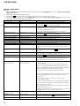
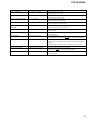
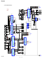
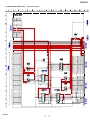
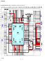
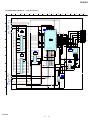
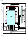
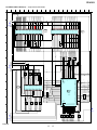
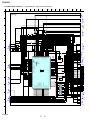
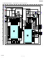
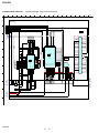
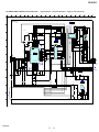
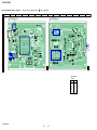
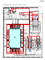
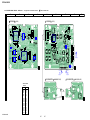
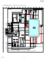
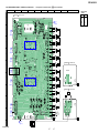
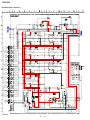
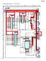
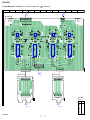
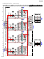
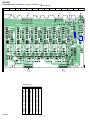
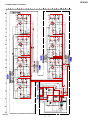
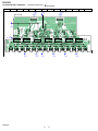
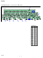
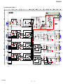
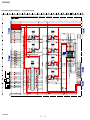
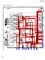
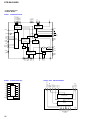
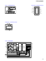
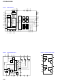
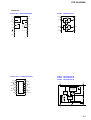
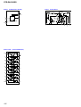
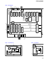
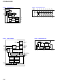
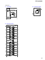
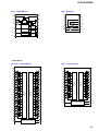
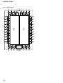
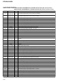
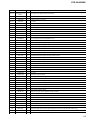
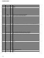
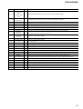
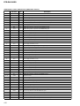
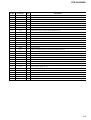
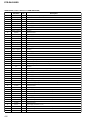
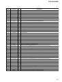
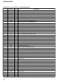
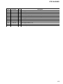
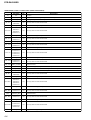
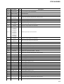
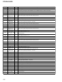
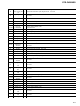
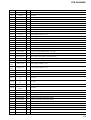
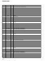
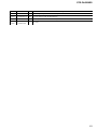
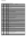
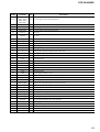
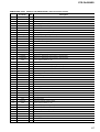
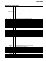
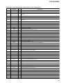
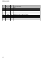
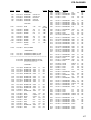
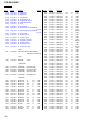
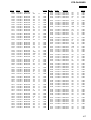
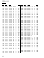
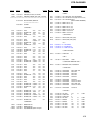
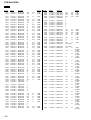
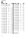
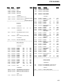
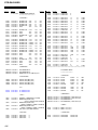
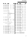
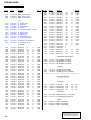
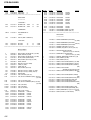
STR-DA5200ES
HDMI BOARD IC3610 MB91F353APMT-A3GUI-X100 (HDMI CONTROLLER)
Pin No.
Pin Name
I/O
1 to 8
SRAM_IO0 to
SRAM_IO8
I/O
9 to 16
17
SRAM_IO9/YAM
AHA_D0 to
I/O
SRAM_IO16/YA
MADA_D8
Description
Two-way data bus with the SD-RAM
Two-way data bus with the SD-RAM and OSD controller
YAMAHA_PS0
O
Address signal output to the OSD controller
18
VSS
-
Ground terminal
19
VCC
-
Power supply terminal (+3.3V)
20, 21
SRAM_A1/YAM
AHA_PS1,
SRAM_A2/YAM
AHA_PS2
O
Address signal output to the SD-RAM and OSD controller
22 to 36
SRAM_A3 to
SRAM_A16,
SRAM_A0
O
Address signal output to the SD-RAM
37 to 39
NO USE
-
Not used
40
VSS
-
Ground terminal
41
UC3V SCL
O
Serial data transfer clock signal output to the HDMI section
42
UC3V SDA
I/O
Two-way data bus with the HDMI section
43
VSS
-
Ground terminal
44
VCC
-
Power supply terminal (+3.3V)
45
YAMAHA_
WAIT_N
O
Wait signal output to the OSD controller
46
NO USE
-
Not used
47
YAMAHA_
READY_N
-
Not used
48
RDX
O
Read enable signal output to the buffer, AND gate, SD-RAM and OSD controller
49
WR0
O
Write enable signal output to the SD-RAM and OSD controller
50
WR1
O
Write enable signal output to the SD-RAM
51
NMIX
-
Not used
52 to 54
MD2 to MD0
I
Model setting terminal
55
RESET
I
System reset signal input from the main system controller "L": reset
56
VCC
-
Power supply terminal (+3.3V)
58
X0
I
System clock input terminal (12.5 MHz)
59
VSS
-
Ground terminal
60
X0A
-
Not used
61
Not used
X1A
-
62
DAC_CLK_SEL
O
Clock on/off signal output terminal for D/A converter
63
NO USE
-
Not used
64
EN3_EEPROM_
UCOM
O
Write enable signal output to the EEPROM
65
TMOS_OE
O
Output enable signal output to the HDMI input select
66
SRAM_CE
O
Chip enable signal output to the SD-RAM
67
YAMAHA_CE
O
Chip enable signal output to the OSD controller
68
OSD_FLASH_CE
-
Not used
69
NO USE
-
Not used
134