1
Service Manual
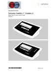
Sartorius Combics 1 | Combics 2
Models CIS1U | CIS2U | CISL1U | CISL2U
for Combics Indicators
and
CF
REF
OK
Models CAPP.U-...-LU | CAPS.U-...-LU
for Combics Weighing Platforms
including Service Specifications
WCI5005-e02101
Contents
04
04
05
05
07
07
08
09
09
10
10
12
12
13
14
14
14
15
15
16
17
17
19
19
22
2
Overview
Service Concept
General Information
When to Use Which Procedure
Combics Indicators
Overview of the Models
Auxiliary Service Tools and Equipment
Accompanying Literature
Operating Concept
Keys below the Display
Configuring the Combics
Purpose, Features
Function of the Keys when Configuring the Menu
Printing the Parameter Settings
Description of the Equipment
Function of the Service Keys and Switches
A. Menu Access Switch
B. SBI/BPI Key
Activating the BPI Mode
C. Boot Key
Activating the xBPI Protocol
Activating the Service Mode
Activating the Service Mode
Working in the Service Mode
Additional Menus in Service Mode
Menu Item 1-18:
Entering Calibration/Linearization Weights
22
23
24
25
26
27
28
28
30
30
33
34
36
36
39
40
40
46
46
1-18-1:
External User-defined Calibration
Weight (Service Mode not Required)
1-18-2
1. Entering 1st Linearization Weight
Calibration/Adjustment Routines in Service Mode (General
Information)
Valid areas for Use
Zone “D”
Menu Line 1-9: Calibration/Adjustment Functions
1-9-1 External Calibration/Adjustment with Default
Weights
1-9-3 External Calibration/Adjustment with Userdefined Weights
1-9-5 Internal Linearization (Only for WP1 on COM1 or
UniCOM Ports)
1-9-7 External Linearization with User-defined Weights
1-9-8 Setting the Preload
1-9-9 Clearing the Preload
Adjustment without Weights
Menu Item 1-19:
Entering the Specifications of the Load Cell(s)
Menu Item 1-20: Entering the Geographical Latitude and
Altitude, or the Acceleration of Earth Gravity
Entering the Place of Adjustment with Subsequent
Adjustment (Example)
Menu Item 1-13: Zero at On
Configuring the A/D Converter of the Combics Indicator
(Service Mode)
Menu Item 11: A/D Converter Settings (Configuration:
Standard, Trade)
47
47
48
49
52
57
58
62
64
65
67
68
69
69
70
70
71
72
73
73
74
75
75
A/D Converter Configuration (General Information)
Notes on A/D Converter Configuration
Descriptions of the Individual Menu Items
Selecting the Weighing Range Structure
(Menu Item 11-3)
Menu Item 9-1: A/D Converter Configuration (Example:
Trade Configuration)
Menu Item 9-1: A/D Converter Configuration with Load
Cell(s) Connected (Example: Standard Configuration)
Loading the Standard Configuration
(if the Trade configuration is currently loaded)
Menu Item 1-19: Entering the Specifications of the Load
Cell(s)
Entering the Date of Service
Entering the Serial Number of the Combics Indicator
Entering the Model Designation of the Combics Indicator
Defining Transaction Numbers for Data Records (Weight
Values) which were stored in the Alibi Memory
Repairing the Combics Indicator
Replacing the Front Panel
Blank Display
Replacing the Power Cord
Replacing the Power PCB
Replacing the DC/DC Converter
Replacing the A/D Converter
Quick-test of the A/D Converter
Replacing the Digital PCB
Checking the IP67 Protection
Torque Values for Cable Glands and Vent Valve
76 Adjusting the Weighing Platform
76 Adjusting the Off-center Load
76 Procedure (Example Illustrated on the Left)
77 Diagram: Determining the Adjustment Resistance
78 Off-center Load Adjustment: 0-ohm Resistors (Example)
79 Setting the Overload Stops
79
1. Weighing Platforms with 1 Load Cell: Steel
80
2. Weighing Platforms with 1 Load Cell: Stainless Steel
81
3. Weighing Platforms with 4 Load Cells: Steel
82
4. Weighing Platforms with 4 Load Cells: Stainless Steel
83 Repairing the Weighing Platforms
83 Replacing the Connecting Cable
84 Replacing Load Cells
85 Torque Values
86 Pin Assignments in the Junction Box
87 Replacing the Load Cell Foot
87 Color Codes of the Wiring for Weighing Platforms, Models
CAPS../CAPS..
88 Error Codes
90 The Combics Weighing Platforms
91 Type Designation
91 Complete Combics scale
92 Complete Combics stainless steel scale
93 Service Specifications
93 CAPP/CAPS1U-.....-LU
94 CAPP/CAPS4U-.....-LU
3
Overview
Service Concept
Prerequisites for performing maintenance and repair work on Sartorius Combics
scales requires considerable experience with both indicators and weighing platforms.
In case of defects, repairs are performed on site. Generally, the equipment is not
replaced.
General Information
– Do not connect or disconnect cables to or from the equipment; always disconnect the
power cable from the wall socket (mains supply) first!
– To ensure safety, an isolating transformer must be installed between the indicator and
the power supply before performing work that entails opening the Combics indicator
housing.
On Combics scales, check and adjust as necessary:
(The procedure is the same as for all scale and weighing platform models.)
– Repeatability (standard deviation)
– Off-center load
– Span
– Linearity
4
When to Use Which Procedure
Combics Indicators
Activate the service mode
to perform all adjustments
Important:
All adjustments required after repair work (such as
replacement of the A/D converter or the load cells) are
performed using the terminal.
The Sartocas service software is not required for these adjustments.
Using this software, however, can make some adjustments
unnecessary (see „Use Sartocas software“ below).
Activate the BPI mode
to load a modified data record in the controller
of the A/D converter
Activate the xBPI protocal
to perform calibration and adjustment, if necessary
using Sartocas
Use Sartocas software
- to reactivate the SBI protocol by selecting the „Close“
command on the Combics terminal (or by restoring
factory defaults (menu line 9-1)
- to program a new A/D converter PCB with data read from the old PCB
See page 17
See page 15
See page 16
The necessary adjustments and customer specific menu settings
are not necessary
5
Use PPLoader software
Drift, display
Inf 02 when starting an
adjustment routine
Display blank (dark)
No communication with
connected equipment
6
to update the application software in the terminal
to check the A/D converter (quick-test)
or with the strain-gauge simulator,
check load cell(s) with the load cell tester
Disconnect the equipment from the power supply and
disconnect all cables and wires from the subassemblies,
connect equipment to power again, connect subassemblies
in turn and measure voltages
Check connections and data transfer parameters;
start internal test program; if necessary, replace
See page 73
See pages 70-72
Overview of the Models
The hardware configuration consists of either a Combics 1 or 2 indicator and
Sartorius weighing platform(s), or a Combics 1 or 2 indicator and weighing
platform(s) (strain-gauge load cells) from another manufacturer.
Important:
Mechanical and electrical service or repair work on the Combics scale requires
considerable experience, and for this reason should be performed only by
Sartorius technicians trained at the factory. Any attempt to perform repair work
can result in damage to the equipment.
Auxiliary Service Tools and Equipment
In addition to standard tools, you will need the following special tools to work on
the Combics scale:
Qty. Designation
Order No.
1
1
6740-33
1
1
1
1
1
1
Laptop
Sartocas service software,
version 1.46 or later
or
Psion Server version 4.10 or later
PPLoader software
Isolating transformer
Flintec LCT-01 load cell tester
Socket wrench, double hexagon, 10-32 mm,
“ square driver
Adapter for Allen screws, SW 5 - 17, ” square driver
7
Qty. Designation
1
1
1
1
2
2
1
1
1
1
1
1
1
1
1
Order No.
Torque wrench, 10-120 Nm 14x18, stainless steel
Torque wrench, 60-320 Nm 14x18, stainless steel
Set of open-ended wrenches with sockets
Set of sockets, up to 30 mm (hexagonal, stainless steel)
Transport belt (to move load plates or weighing
platforms; available from specialist suppliers)
Ring lugs (stainless steel; for moving the load plates or
weighing platforms; available from specialist suppliers)
Set open-ended wrenches (spanners) (up to 24 mm, stainless steel)
Threaded rod, M 16x120, for lifting the weighing platform
(available from specialist supplier)
Testing device for checking IP66/67 protection (not yet defined)
Set of screwdrivers (slotted)
Set of screwdrivers (Phillips head )
Set of Allen wrenches
Digital voltmeter (Beckman)
6738-62
Strain gauge simulator
6740-74
RS-232/485 converter
6740-68
Accompanying Literature
Operating instructions for “Combics 1 | 2 Indicators“
Operating instructions for “Painted or Stainless Steel Weighing Platforms“
8
WCI6004-e03081
WCA6004-e03081
98648-012-27
98648-012-26
Operating Concept
Combics 1
Combics_1Folie_u.eps
Keys below the Display
e
On/off
(On)
Turns the Combics on and off.
(Standby) Combics switched off displays
“off“.
n
Toggle the display between
(Scale #) the weighing platforms
(Combics 2 only)
With two weighing platforms
connected, this key toggles
the display between the two
readouts.
(
(Zero)
During weighing:
Zero the scale
In the operating menu:
Closes active submenu and
returns to next higher menu
level and menu level (unless
the first menu level is already
shown)
During alphanumeric input
in the operating menu:
– Press briefly:
Activate character to the left
of the currently active
character
(with the first character
active: Exit the input mode
without saving changes)
– Press and hold (> 2 sec ):
Exit the input mode without
saving changes
)
During weighing:
(Tare) – Press briefly:
Tare the scale
– Press and hold (> 2 sec ):
Calibration/adjustment
In the operating menu:
– Press briefly:
Display the next lower menu
level or
Select and store a menu item
– Press and hold (> 2 sec ):
Exit the operating menu
During alphanumeric input in the
operating menu:
– Press briefly:
Activate character/s to the
right of the currently active
character ®
(after the last character:
store input)
– Press and hold (> 2 sec ):
Store current input and display
the menu item
k
During weighing:
(Function)Toggle (depends on operating
menu settings) between:
– first and second weight unit or
– gross and net or
– normal and 10-fold increased
display resolution
In the operating menu:
Show the next item on the
same menu level (scroll
through values in series)
9
During alphanumeric input
in the operating menu:
– Cursor in first position,
no characters entered yet:
Delete entire string and
enter “0“
– Change the displayed
character; scroll forward
(sequence: 0 through 9,
decimal point, minus
sign, Z through A, pace)
p
(Print)
10
During weighing:
– Press briefly:
Print
– Press and hold (> 2 sec ):
Print GMP footer
In the operating menu:
Print the menu settings
starting from the current
position; or print Info data
During alphanumeric input in
the operating menu:
– Cursor in first position, no
characters entered yet:
Delete entire string and
enter a space
–
Change the displayed
character; scroll
backwards ÿ (sequence:
Space, A through Z,
minus sign, decimal
point, 9 through 0)
Note:
The sequence in which keys are
pressed in the following
descriptions (“Key sequence:“)
are given as examples only.
Other sequences are possible.
Combics 2
Combics_2Folie_u.eps
Configuring the Combics
Purpose
You can configure the Combics to
meet individual requirements by
entering user data and setting
selected parameters in the operating
menu. The operating menu is a
combination of text levels and
numeric codes.
Features
The operating menu parameters are
divided into the following categories
1. Text-menu level
–
Application programs »APPL«
–
Key assignments k »fn-key«
–
Device parameters »setup«
–
Device information »InFo«
–
Language for calibration and
adjustment printouts »LAnG«
You can display, enter or change the
following parameters:
–
Application programs »APPL«
In addition to basic weighing
functions, you can use the
Combics 2 to calculate and
display weighing data as follows:
–
Counting
–
Neutral measurement
–
Averaging (animal weighing)
–
Checkweighing
–
Classification
–
Weighing in percent
–
Net-total formulation
–
Totalizing
–
–
–
–
–
–
–
–
Function: Key assignment for k
»fn-key«
Gross/net toggling
»gro net«
Toggle between the 1st, 2nd and
3nd weight unit
(are eycled in the display)
»3. unit«
10-fold higher resolution
»Res 10«
Device parameters »setup«
Device configuration, i.e.,
to meet individual requirements
by selecting predefined menu
parameters in the operating
menu. The device parameters
are combined in the following
groups :
Weighing platform »wp1«
Interfaces (COM1 and optional
UniCOM)
Digital control line »ctrl in«
Bar code scanner »barcode«
–
Printer protocols »prtport«
–
Extra Functions: Utilities
»utilit«.
Timer »time«
Date »date«
Set user password »code«
–
–
–
–
Display device information
»info« (serial number, etc.)
–
Language for calibration and
adjustment records »lang«.
Select the language.
The rest of the menu
is language-independent.
11
(Function)
Functions of the Keys when
Configuring the Menu
Open the operating menu:
Turn the Combics off and on
again by pressing e; while all
segments are displayed, press the
) key briefly.
Navigating in the operating
menu:
–
(O)
(Print)
–
–
–
–
(On)
(Tare)
–
–
–
–
–
12
(Function)
Scroll :
Press the k key
To the left ¬: Press (
Change and store setting:
Press the ) key
Exit the operating menu:
Press and hold the ) key (> 2
sec)
During alphanumeric input in
the operating menu:
(Tare)
–
–
–
Scroll upwards (0, 1, 2, 3, etc.):
Press the k key
Scroll downwards ¬ (A, B, C, etc.):
Press the p key
Next position: Press the ) key
Previous position: Press the (
key
Exit input mode without saving
changes; with cursor in first
position: Press the ( key
Exit the input mode without
saving changes:
Press and hold the ( key
(> 2 sec)
To confirm your input: Press the
) key with the cursor 1 space
beyond the last position; or press
and hold (> 2 sec)
Confirm currently active
character and move 1 position
to the right:
Press the ) key
Move cursor 1 position to the left
Press the ( key
Printing the Parameter Settings
Generate a printout of the settings on
the current menu level:
Press the p key
>
Printout (example)
The maximum width of this
printout is 20 characters.
-------------------MENU
SETUP
WP1
-------------------1
1.1
1.1.2
1.2.1
...
1.18
1.18.1
CAL.
10.000 kg
etc.
Description of the Equipment
The Combics scales from Sartorius are primarily used in industry. Because there are a number of hardware configurations
to choose from, Combics models are constructed according to customer requirements.
The Combics scale consists of:
– A choice of weighing platforms with capacities from 10 lbs to 10000 lbs (in stainless steel or steel) and indicators
The Combics 1 / 2 indicators consist of:
– Front panel with keypad and
digital display (Combics 2 has
additional keys and LEDs)
Digital PCB with application
processor, memory, RS-232 interfaces
Combics 2
– Combics indicators
are equipped with either cable
glands or D-Sub 25
connectors.
Note:
combics_15_klemmen.eps
Analog/digital converter
Power PCB
DC/DC converter
(Combics2 has a clock chip)
Additional electronic subassemblies are optional.
13
Function of the Service Keys and Switches
A. Menu Access Switch
A
This switch must be open to work with the service software or configure the A/
D converter (e. g., “Trade” configuration). If the menu access switch is closed,
the error message “ACCESS SWITCH LOCKED” is displayed in the service program
and the indicator shows “L” (underload) or “H” (overload). In this case, the A/D
converter cannot be configured. If adjustment is necessary (span, linearity), the
“± 2%” window is active.
B. SBI/BPI Key
closed
open
verriegelungs_schalter.eps
To use the Sartocas program (v 1.46 or later) or Psion server (v 4.10 or later).
the Combics indicator must be in BPI (binary processor interface) mode (for
example, to load a modified data record from the A/D converter into its
controller). This setting is valid for the COM1 port.
Note:
B
sbi_bpi_taster.jpg
14
To perform adjustment only with the service software, the COM1
interface is set to the xBPI (eXtended Binary Processor Interface) protocol
and the laptop or Psion server connected to that port.
Activating the BPI Mode
– Turn on the Combics.
– In weighing mode, press and hold the SBI/BPI key for approx.
5 seconds (the weight readout goes blank).
– Release the switch.
– Turn the Combics off and then on again.
– The Combics is now in BPI mode.
Important:
Peripheral devices that communicate over the SBI (Sartorius Balance Interface)
protocol cannot be operated while the Combics is in BPI mode.
If you press the p key, only InF 30 is displayed.
To return the indicator to the SBI mode, either use the “Close” function in the
Sartocas service software or a Psion server (and then turn the Combics off and
back on again), or select the Menu Reset option (9 - 1 - 1) in the Combics
operating menu.
C. Boot Key
Activate this switch only if an attempt to program the application memory
with the PPLoader program fails (programming routine stops responding).
Procedure for making the PCB bootable:
– Disconnect the Combics from the main power.
– Press and hold the boot switch (approx. 3 sec.) while reconnecting the Combics
to power.
– Release the switch. After a brief period, the PCB is bootable again
(load application software again with the PPLoader program).
C
boot_taster.jpg
15
Activating the xBPI Protocol
Activate the xBPI protocol to perform adjustment with the service software
Sartocas software or Psion server without activating the BPI mode
through the SBI/BPI key.
Note:
This menu item is accessible in the standard menu.
– Via Setup select the Device parameters menu item (for the COM1 port).
– Open the Device parameters menu and scroll down to the Interface
submenu.
– Open the Interface submenu and activate the xBPI menu item.
Display_xbpi.eps
Note:
16
Under xBPI a submenu is opened for assigning addresses, but this function is only
available when using xBPI with RS-485.
Activating the Service Mode
Activating the Service Mode
– Turn off the Combics (key: e).
– Turn on the Combics (key: e) and briefly press the ) key while all
segments are displayed.
display.eps
The display shows APPL.
appl.eps
– Press the k key to scroll to the Setup item.
setup.eps
– Press the ) key; WP-1 is displayed.
display_wp1.eps
– Press the k key to scroll to the CodE item.
code.eps
17
– Press the ) key; the display shows only a flashing cursor.
d_vore12.eps
– Press k to select “2” and then press ) to confirm; the cursor jumps to the
second position; now you can enter the next number. Repeat this procedure
with the appropriate numbers to enter the service password (202122).
202122.eps
If you find that one of the numbers is wrong, press ( to go back to that digit
and change it; then press the ) key repeatedly to return to the sixth digit
(the 2 flashes).
Note:
code_s.eps
– After entering the last digit, press ) (< 2 sec.) and ( ( (in that order)
to activate the service mode. Setup appears in the display.
A “S” in the upper right-hand corner of the display indicates that the service
mode is active.
To cancel the password input process before it is finished, press ( repeatedly
until CodE is displayed.
Note:
Important:
18
The service mode can be deactivated only by turning the off the Combics indicator.
When the service mode is active (password 202122), you can only view the
customer password. The customer password can be deleted only by entering
the general password (40414243) or the customers password.
Working in the Service Mode
Note:
When performing maintenance on an existing system, the service mode must be
activated to perform linearization, to set or clear the preload, and to enter the
date of service.
Additional Menus in Service Mode
In the Text Menu (“Setup”)
Under the “Date” (DATE) and “Password” (CodE) menu items:
– Date of service S-DATE
– Memory number MEM-NO
– Indicator serial number SER-NO
– Model designation ModEL
In the numeric menu:
The Setup menu for WP1 (WP-1) and the COM1 (COM1) and
UniCOM (UNICOM) ports is extended by the following items for
configuring weighing platforms WP1 (WP-1) and WP2 (WP-2):
1-9
Calibration/adjustment functions:
1-9-1: Ext. calibration/adjustment with default weight
(service mode not required)
1-9-3: Ext. calibration/adjustment with user-defined weight
(service mode not required)
1-9-5: Internal linearization (only for WP2 on COM1 and UniCOM ports)
1-9-7: External linearization with user-defined weights
1-9-8: Set preload
1-9-9: Clear preload
1-9-10: Key blocked (service mode not required)
19
Note: After necessary adjustments, install the suitable
adjustment routine for the customer.
1-18
1-18-1:
1-18-2:
1-18-3:
1-18-4:
1-18-5:
Enter the calibration and linearization weights
Enter adjustment weight
Enter linearization weight 1
Enter linearization weight 2
Enter linearization weight 3
Enter linearization weight 4
Calibration without weights (by entering the
specifications of the load cell(s)):
1-19-1: Nominal load
1-19-2: Resolution
1-19-3: Sensitivity in mV/V for cell 1 (or mean derived
from all load cells)
1-19-4: Sensitivity in mV/V for cell 2
1-19-5: Sensitivity in mV/V for cell 3
1-19-6: Sensitivity in mV/V for cell 4
When multiple cells are connected, either the
individual values are entered under items
1-19-3 to 1-19-6, or the mean derived from all
load cells is entered under 1-19-3.
1-19-7: Store values entered for 1-19
1-20
1-20-1:
1-20-2:
1-20-3:
1-20-4:
8-12
Geographical data is displayed before every
span adjustment
9-1
9-1-3:
9-1-4:
9-1-10:
Restore factory settings / Reset menu
Load “Standard” configuration
Load “Trade” configuration
Load default setting and delete all Parameters
11
11-1
11-1-4:
11-2
11-2-1:
11-2-2:
11-2-3:
...
11-2-21:
A/D Converter Settings:
Accuracy classes:
Accuracy class l
1. Weight unit (copy from menu subset 1-7):
long ton
Grams
Kilograms
1-19
20
Place of adjustment (geographical latitude
and altitude or, alternatively, the acceleration
of gravity at the place of installation):
Latitude in degrees
Altitude in meters above sea level
Acceleration of gravity
Store values entered for 1-20
Tons
11-3
11-3-1:
11-3-2:
11-3-3:
Weighing range:
Single-range scale
Multiple-range scale
Multi-interval scale
11-4
11-4-1:
11-4-2:
11-4-3:
11-4-4:
Metrological data for single-range scale:
Scale interval d
Verification scale interval e
Minimum load
Maximum load
11-5
11-5-1:
11-5-2:
11-5-3:
11-5-4:
11-5-5:
11-5-6:
11-5-7:
Metrological data for multi-interval scale:
Scale interval d
Verification scale interval e
Minimum load
Range 1
Range 2
Range 3
Maximum load
11-6
11-6-1:
11-6-2:
11-6-3:
11-6-4:
11-6-5:
11-6-6:
11-6-7:
Metrological data for multiple-range scale:
Scale interval d
Verification scale interval e
Minimum load
Range 1
Range 2
Range 3
Maximum load
11-7
11-7-1:
11-7-2:
11-7-3:
...
11-7-5:
...
11-7-21:
Available weight units:
User-defined unit
Grams
Kilograms
11-8
11-8-1:
11-8-2:
11-8-3:
...
11-8-5:
...
11-8-21:
Calibration/adjustment unit:
User-defined unit
Grams
Kilograms
lb
Tons
lb
Tons
11-10
Store A/D converter configuration:
11-10-1: Store
11-10-2: Do not store
21
Menu Item 1-18: Entering Calibration/Linearization Weights
1-18-1: External User-defined Calibration Weight (Service Mode not Required)
– Activate the service mode (see page 16).
– Select weighing platform “WP1”.
display_wps1_serv.eps
– Press the ) key to open the numeric menu.
display_serv_01.eps
menu_1181.eps
– Select menu item 1-18-1 (external user-defined weight) by pressing k )
repeatedly.
– Activate input mode for the user-defined weight (press ) briefly).
The first digit flashes.
user1Ib.eps
– Enter the user-defined weight (in this example: 10,000 lb) (key sequence:
) k ) p ) ) ) k )). The last number entered flashes.
user2Ib.eps
– Press the ) key again to store the user-defined weight; the menu jumps back
to 1-18-1.
– To exit the service mode, press and hold the ) key for longer than 2 seconds.
menu_1181.eps
22
1-18-2: 1. Entering Linearization Weight
– Scroll to menu item 1-18-2 (press k repeatedly).
Note:
The service mode must be active.
menu_1182.eps
– Activate the input mode for the first linearization weight (press the ) key
briefly). The first number flashes.
user1Ib.eps
– 1. Enter the linearization weight (in this example: 2,500 lb) (key sequence:
3 x k, ) p ) 6 x k, ) k ) k). The last number entered
flashes.
userl2Ib.eps
– Press and hold the ) key (> 2 sec.) to store the value for the first
linearization weight. The menu jumps back to item 1-18-2.
menu_1182.eps
– Follow the above steps for menu items 1-18-3, 1-18-4, and 1-18-5 to enter
values for the second, third and fourth linearization weights as well.
Enter “0” instead of a weight value for unused linearization points.
– At the end of input, the display must show menu item 1-18-5.
– To exit the service mode, press and hold the ) key for longer than 2 seconds.
menu_1185.eps
23
Calibration/Adjustment Routines in Service Mode (General Information)
There are three ways to adjust the span:
– Using external weights
– By entering the specifications of the load cell(s) (sensitivity in mV/V)
– By entering geographical data (latitude and altitude of the place of use) or by
entering the acceleration of gravity (at the place of use)
Span adjustment with external weights always takes precedence.
What does this mean when performing service work?
If a weighing system is used in a location other than that for which it was
originally intended (i.e., the geographical data at the new place of use does not
match the entered at Sartorius AG in Goettingen, Germany), the scale span can be
adjusted by using external weights or by entering the specifications of the load
cell(s). In this case, the geographical data entered for the original place of use is
no longer valid. The same applies for span adjustment performed after any repair
work on the weighing system.
Once you store the geographical data or acceleration of gravity at the place of use
and subsequently perform span adjustment using weights, the scale is correctly
programmed and adjusted.
You can now enter the geographical data of the new place of use to adapt the
scale for use at that location.
24
If the acceleration of gravity has been entered, this data takes precedence over
any
geographical data (latitude and altitude) previously entered.
Valid Locations for Use
Once the exact geographical data or the acceleration of gravity has been entered
and subsequent span adjustment performed, a scale with a resolution of 3000
digits can be used within a tolerance zone of ±100 km from the latitude entered
and ±200 m from the altitude.
The same applies when the acceleration of gravity is entered.
The following values are entered when the Combics scale is adjusted
in Goettingen, Germany:
– Latitude: 51.53 degrees (= 51° 32’)
– Altitude: 151 m
– or the corresponding acceleration of gravity, 9.811590 m/s-2
The greater the precision of the geographical data entered, the greater the
precision achieved with the weighing instrument; the tolerance range, however,
is restricted accordingly (see above).
25
Zone “D”
For a complete scale used in the Federal Republic of Germany, the following data
can be entered for scales with a resolution of 3000 digits at the place of span
adjustment:
– Latitude: 51.00 degrees
– Altitude: 513 m
– or the corresponding acceleration of gravity, 9.810 m/s-2
The area of use valid for this scale is designated “Zone D” (valid only in Germany).
26
Menu Item 1-9: Calibration/Adjustment Functions
Note:
When using a verified weighing platform, open the cover plate on the left side
of the back of the indicator and move the menu access switch to the right
(“accessible”; see page 14).
– Activate the service mode (see page 17).
1-9-1: External Calibration/Adjustment with Default Weights
– Select weighing platform »WP1«.
– Press the ) key to open the numeric menu.
display_wps1_serv.eps
display_serv_01.eps
menu_191.eps
– Select menu item 1-9-1 (external calibration/adjustment with default weights)
(key sequence:
) several times k )) and confirm () key briefly).
When this menu setting is active, you can exit the Service mode by turning the
Combics indicator off and then on again.
27
display_cal.eps
5lb.eps
– After taring or zeroing the scale, press and hold the ) key until Cal is
displayed.
If menu item 8-12-2 is active, the geographical data is displayed before the
calibration weight is prompted. Confirm each of the values shown by pressing
the ) key to continue with the calibration routine.
– After approx. 2 seconds the calibration weight required is shown on the display.
– Place the prompted weight on the scale. After a brief pause, the difference
between the current value and the last is displayed (calibration).
– Press the ( key to stop the calibration/adjustment routine.
display_serv_01lb.eps
– Press the ) key to start the adjustment.
5.0lb.eps
1-9-3 External Calibration/Adjustment with User-defined Weights
– Select weighing platform »WP1«.
display_wps1_serv.eps
– Press the ) key to open the numeric menu.
display_serv_01.eps
28
menu_193.eps
display_cal.eps
– Press ), then, several times, k ) to select menu item 1-9-3, “External
calibration/adjustment with user-defined weights” and confirm by pressing )
briefly.
– Press ( to jump to the first columns of the numeric menu.
– Press ) to store the selected menu item.
– Turn the Combics indicator off and then on again to exit the Service mode.
– After taring or zeroing the scale, press and hold the ) key until Cal is
displayed.
If menu item 8-12-2 is active, the geographical data is displayed before the
calibration weight is prompted. Confirm each of the values shown by pressing
the ) key to continue with the calibration routine.
– After approx. 2 seconds the calibration weight (user-defined weight) required
is shown on the display. Select menu item “1-18-1” to enter the user-defined
weight.
10Ib.eps
display_serv_01Ib.eps
– Place the prompted weight on the scale. After a brief pause, the difference
between the current value and the last span adjustment is displayed
(calibration).
– Press the ( key to stop the calibration/adjustment routine.
– Press the ) key to start the adjustment.
10Ibw.eps
29
1-9-5 Internal Linearization (Only for WP1 on COM1 or UniCOM Ports)
1-9-7 External Linearization with User-defined Weights
– Activate the service mode (see page 17).
– Select weighing platform »WP1«.
Display_WP1_Serv.eps
– Press the ) key to open the numeric menu.
display_serv_01.eps
menu_197.eps
display_lin.eps
30
– Select menu item 1-9-7 (External linearization with user-defined weight) (key
sequence: ), then, several times, k )) and confirm by pressing )
briefly.
– Press and hold the ) key to store the selected menu items and return the
Combics indicator to the weighing mode.
When this menu setting is already active, you can exit the Service mode by
turning the Combics indicator off and then on again.
– After taring or zeroing the scale, press and hold the ) key until Lin is
displayed.
– After approx. 2 seconds the first linearization weight (user-defined weight)
is shown on the display. Select menu items 1-18-2 through 1-18-5 to enter the
linearization weights.
2.5Ib.eps
– Place the prompted weight on the scale. After a brief pause, the difference
between the current value and the last adjustment is displayed (calibration).
– Press the ( key to stop the calibration/adjustment routine.
display_serv_02Ib.eps
– Press the ) key to store the value for the first linearization weight;
the second linearization weight is prompted.
display_5Ib.eps
– Place the prompted weight on the scale. After a brief pause, the difference
between the current value and the last adjustment is displayed (calibration).
display_serv_03lb.eps
– Press the ) key to store the value for the second linearization weight;
the third linearization weight is prompted.
7.5Ib.eps
– Place the prompted weight on the scale. After a brief pause, the difference
between the current value and the last adjustment is displayed (calibration).
display_serv_04lb.eps
31
– Press the ) key to store the value for the third linearization weight;
the fourth linearization weight is prompted.
10Ib.eps
– Place the prompted weight on the scale. After a brief pause, the difference
between the current value and the last adjustment is displayed (calibration).
display_serv_03lb.eps
– Press the ) key to store the value for the fourth linearization weight.
The scale now prompts a requires the zero point (remove all weights from the
load plate).
display_serv_06Ib.eps
– Once the zero point is stored, the Combics automatically returns to the
weighing mode.
0kg.eps
32
1-9-8
Note:
Setting the Preload
When using a verified weighing platform, open the cover plate on the left side
of the back of the indicator and move the menu access switch to the right
(“accessible”; see page 14).
– Activate the service mode (see page 17).
– Select weighing platform »WP1«.
display_wp1_serv.eps
– Press the ) key to open the numeric menu.
display_serv_01.eps
menu_198.eps
– Select menu item 1-9-8 (Set preload) (key sequence: ), then, several times,
k )) and confirm by pressing ) briefly.
– Press and hold the ) key to store the selected menu items and return the
Combics indicator to the weighing mode.
– Press )) to tare the Combics indicator, or press ( to zero it.
If you tare the indicator, “NET” might be displayed.
0lb_o.eps
– Place the preload on the scale.
vorl1.eps
33
– Press ) until SEt VOR is displayed.
vorl2.eps
– Release the ) key; after a brief pause, the Combics indicator automatically
returns to the weighing mode.
0lb_o.eps
1-9-9 Clearing the Preload
Note:
When using a verified weighing platform, open the cover plate on the left side
of the back of the indicator and move the menu access switch to the right
(“accessible”; see page 14).
– Activate the service mode (see page 17).
– Select weighing platform »WP1«.
display_wps1_serv.eps
– Press the ) key to open the numeric menu.
display_serv_01.eps
vorl3.eps
34
– Select menu item 1-9-9 (Clear preload) (key sequence: ), then, several times,
k )) and confirm by pressing ) briefly.
– Press and hold the ) key to store the selected menu items and return the
Combics indicator to the weighing mode.
– Remove the preload weight from the scale. A weight value with a preceding
“minus” sign is displayed (for example, -0.335 lb).
Display_-0335lb.eps
– Press ) until CLr VOR is displayed.
vorl5.eps
– Release the ) key; the preload is cleared and, after a brief pause, the Combics
indicator automatically returns to the weighing mode.
0lb_o.eps
35
Adjustment without Weights
Menu Item 1-19: Entering the Specifications of the Load Cell(s)
– Activate the service mode (see page 17).
– Select weighing platform »WP1«.
display_wps1_serv.eps
– Press the ) key to open the numeric menu.
display_serv_01.eps
– Press the ) key, then, several times, k repeatedly and then ) again to
open menu item 1-19, “Calibration without weights”; then select item 1-19-1,
“Nominal capacity”.
display_serv_01191.eps
– Press ) again to activate menu item 1-19-1.
– Enter the nominal capacity of the load cell(s) (e.g., 30.00 lb).
The nominal capacity has to match the maximum load set under menu item
11-4-4.
display_mxl30Ib.eps
Note:
36
If a weighing platform has more than one load cell, multiply the nominal capacity
accordingly. Example: The weighing platform consists of 4 load cells, each of them
has a capacity of 30 kg.
In this case, the nominal capacity (= maximum load) equals 4 x 30 kg, or 120 kg.
– To store the setting, press and hold the ) key (> 2 sec).
– Select menu item1-19-2 (key sequence: k, )).
– Enter the resolution (lowest scale interval d) (e.g., 0.01 kg). This value has to
match that stored under menu item 11-4-1 (or 11-5-1 or 11-6-1).
display_schrittw_001Ib.eps
– To store the setting, press and hold the ) key (> 2 sec).
– Select menu item1-19-3 (key sequence: k, )).
Enter the sensitivity of the load cell in mV/V (usually listed in the load cell
specification sheets). If a weighing platform consists of more than one load cell,
enter here the sensitivity of load cell 1.
Example: The sensitivity of the load cell is 1.9440 mV/V.
display_wze19440.eps
Note:
– To store the setting, press and hold the ) key (> 2 sec).
If a weighing platform consists of more than one load cell, enter the sensitivity
values for the other cells (up to 4) under menu items 1-19-4 (for load cell 2)
through 1-19-6 (for load cell 4) and confirm each value (k ) keys).
If the platform has less than four load cells, enter “0.000” under the unused menu
items.
37
– Press k and ) to select menu item 1-19-7,
Store parameters set in menu item 1-19.
display_serv_01197.eps
– Press ) ( ( to store the load cell specifications entered; the menu
automatically jumps back to the first menu page.
display_serv_01.eps
38
– Exit the operating menu and return to the weighing mode.
Menu Item 1-20: Entering the Geographical Latitude and Altitude,
or the Acceleration of Gravity
When you activate menu item 1-20-1, the value 99999.99 is displayed; under
1-20-2, is 9999999 displayed too. Otherwise, if values have already been entered
for geographical latitude and altitude, then 0.000000 is displayed under menu
item 1-20-3.
During calibration, the Combics show will whether and which gravimetric data
(geographical latitude and altitude, or acceleration of gravity) is used, if the menu
item 8-12-2 is activated.
If latitude and altitude are used, the display shows “Altitude” for 2 seconds when
the calibration procedure is started (CAL), followed by the configured elevation
above sea level in meters. Press ) to confirm this information. Next, the display
shows “LATITUDE” for 2 seconds, followed by the value set for the geographical
latitude (in degrees). Press ) to confirm this information. The calibration
weight is now prompted. If the acceleration of gravity is given rather than the
geographical latitude and elevation, the display shows “GRAVITY” for 2 seconds
(after “CAL”), followed by the value entered for the local acceleration of gravity.
Press ) to confirm this information.
However, if the calibration weight is prompted as soon as the “CAL” display goes
out, this means whether the correction of the calibration factor has been
deactivated nor the menu item 8-12-2 is activated; in other words, neither the
geographical latitude and altitude nor the acceleration of gravity have been
entered under menu line 1-20.
39
Entering the Place of Adjustment with Subsequent Adjustment (Example)
– Activate the service mode (see page 17).
– Press ) to select weighing platform »WP1«.
display_wp1_serv.eps
– Press the ) key to open the numeric menu. The first menu page is displayed.
display_serv_01.eps
– Open menu line 1-20, “Place of adjustment”, by pressing k and ).
Menu item 1-20-1 (latitude) is displayed.
display_serv_01201.eps
Important:
40
If the geographical latitude and altitude of the place of installation are known,
enter this data under menu items 1-20-1 (latitude) and 1-20-2 (altitude).
If you wish to use the acceleration of gravity at the place of installation for the
basis of adjustment rather than these two parameters, enter this value under
menu item 1-20-3.
A value entered for acceleration of gravity takes precedence over the
combination of geographical latitude and altitude.
Example:
Entering geographical latitude and elevation:
Select menu item 1-20-1 (latitude) (press )).
In the example shown here, the most recently entered parameter was the value for
the acceleration of gravity (menu item 1-20-3). For this reason, the input fields
for menu items 1-20-1 and 1-20-2 are filled with 999…
display_999.eps
display_5153.eps
In the example shown here, the geographical latitude of Goettingen, Germany,
was the value entered most recently. This value is the reference value, for which
no correction of the span adjustment was made with respect to the place of
installation, assuming that “151” (elevation in meters above sea level) has been
entered under menu item 1-20-2.
Enter the geographical latitude of the place of installation (or the reference
value 51.53) as a positive decimal number (convert angular minutes to decimal
places). Press ) to confirm your input.
display_999.eps
– Select menu item 1-20-2 (“Elevation at the place of installation”) (key
sequence: ) k )).
The input field is filled with 999…, because the last value entered in menu line
1-20 was the acceleration of gravity (menu item 1-20-3).
41
– Enter a value for the local elevation at the place of installation in meters above
sea level (reference value: 151) (key sequence: ) k k).
display_151.eps
Note:
A negative value may be entered for local elevation; for example,
if the scale is installed in a mine.
– Press ) to confirm your input.
– Activate menu item 1-20-4 to store new data
(key sequence: ) k k).
Rather than the geographical latitude and local elevation of the place of
installation, you can enter a value for the acceleration of gravity at the place of
installation (menu item 1-20-3).
Example:
Entering the acceleration of gravity place of installation.
– Select menu item 1-20-3 (acceleration of gravity) (key sequence: k k )).
Example:
display_000.eps
display_981.eps
42
In the example shown here, the geographical latitude and local
altitude (menu items 1-20-1 and 1-20-2) were the last parameters
entered in menu line 1-20. Thus the input field for acceleration of
gravity is filled with 000…
In the example shown here, the most recently entered parameter
was the value for the acceleration of gravity at Goettingen, Germany
(menu item 1-20-3). This value is the reference value, which means
no correction of the span adjustment for the place of installation
is required.
– Enter the acceleration of gravity at the place of installation (in ms-2 / or the
reference value: 9.811590). Press ) to confirm your input.
– Activate menu item 1-20-4 to store new data (key sequence: ) k).
The display shows “busy”, indicating that the parameters entered are being stored.
display_busy.eps
– Restart the scale: Turn the indicator off and then on again (key sequence: e
e, or press and hold the ) key (> 2 sec).
After the self-test of the display, the scale is ready to operate.
display.eps
Note:
Once the precise geographical data or acceleration of gravity has been entered, the
tolerance range is restricted (see page 23).
– After data has been entered as described above, the span must
be adjusted.
Example
Settings (changes in the factory settings required for this example):
Menu item 1-9-1: External calibration/adjustment with default weight;
Menu item 1-10-1:
Calibration/adjustment in one operation;
Menu item 1-16-1:
External calibration/adjustment/linearization
accessible.
43
The parameters for altitude at the place of installation and geographical latitude
have been entered (menu items 1-20-1 and 1-20-2).
The display will show “ALTITUD” for 2 seconds, if the menu item 8-12-2 is activated.
display_altitud.eps
The altitude at the place of installation is displayed in meters above sea level.
In the example shown here, the altitude of Goettingen, Germany (reference value)
is shown.
display_alt_151.eps
– Press the ) key to confirm the displayed value.
The display shows “LATITUD” for 2 seconds.
display_latitud.eps
display_lat_5153.eps
The geographical latitude of the place of installation is shown in degrees north
or degrees south.
In the example shown here, the altitude of Goettingen, Germany (reference value)
is shown.
– Press the ) key to confirm the displayed value.
10Ib.eps
– Place the prompted calibration weight on the scale (see page 25 for details on
calibration and adjustment).
or
44
display_gravity.eps
Instead of “ALTITUD” and “LATITUD”, “GRAVITY” is displayed for 2 seconds if the
acceleration of gravity (menu item 1-20-3) was entered rather than the elevation
and geographical latitude (menu items 1-20-1 and 1-20-2).
The value entered for the acceleration of gravity at the place of installation
is displayed (in m/s-2).
In the example shown here, the acceleration of gravity at Goettingen, Germany
(reference value) is shown.
display_grav_981.eps
This data is shown when menu item 8-12-2 is active.
– Press the ) key to confirm the displayed value.
– Place the prompted calibration weight on the scale (see page 25 for details on
calibration and adjustment).
10Ib.eps
45
Configuring the A/D Converter in the Combics Indicator (Service Mode)
The A/D converter must be configured in the following cases:
– To adapt the existing configuration to customer requirements (for example,
to change the nominal capacity or the resolution).
– To adapt the Combics for use with any commercially available strain-gauge
load cell or analog Sartorius CAPP or CAPS weighing platform, when installing
a new system.
– After replacing the electronic A/D converter during repair work, also on
combics scales, when the Sartocas software is not used.
Menu Item 11: A/D Converter Settings (Configuration: Standard, Trade)
Note:
46
Before the A/D converter can be configured, you need to load either the
“Standard” configuration or the “Trade” configuration, depending on customer
requirements.
– 9-1-3: Load “Standard” configuration
– 9-1-4: Load “Trade” configuration
Menu Item 11:
A/D Converter Configuration (General Information)
Note:
Access is restricted by a special password.
Features
With the menu access switch open, you can
configure most of the parameters affecting
the following specifications:
– Toggling between Standard and Trade configurations
(for use in legal metrology)
–
–
–
–
–
–
–
Verification scale interval e
Scale interval d
Minimum load
Maximum load
Maximum load for a given range
Verification scale interval e for a given range
User-definable weight units
These parameters are not reset when you restore the
factory defaults in the operating menu.
Parameters not listed above are not affected by your
choice of Standard or Trade configuration; the same
restrictions apply as for Sartorius weighing instruments
which cannot be configured.
Note on A/D Converter Configuration
A/D converter configuration is performed using the
numeric menu (weighing platform 1).
Important: The A/D converter can be configured only in
the service mode.
The maximum load for each weighing range must be
entered in an appropriate weight unit. Select the desired
weight unit for operation under menu line 11-7, “Weight
units”. The maximum load for each range must be a value
that can be displayed in any available weight unit.
Weight units that are accessible (or blocked) for use as
Weight unit 1 are also available (or blocked) for use as
Weight unit 2. The weight unit used for the configuration
cannot be blocked.
Checking and Configuring the Equipment for Use in Legal
Metrology:
47
Following A/D converter configuration, write the
metrological data on a tag for all weighing ranges.
Afterwards, affix the enclosed protective acetate overlay
to the tag.
After completing calibration and adjustment, move the
menu access switch back to the “closed” position and then
turn the Combics indicator off and back on again to
activate the new configuration.
Open menu line 1-7 to make sure only the permitted
weight units are accessible.
Perform necessary routines for scales used in legal
metrology.
– Standard Configuration
(menu item 9-1-3)
or
– Trade Configuration
(menu item 9-1-4)
Menu Line 11-1 (Accuracy Class)
This menu line is not shown when the Standard
configuration is active.
When the Trade configuration is active (for verifiable or
verified weighing platforms), only menu item 11-1-4 is
shown.
Select the accuracy class appropriate for the weighing
platform connected. Which class is appropriate depends
on the load cell(s) installed.
Descriptions of the Individual Menu Items
Menu Item 9-1-3 / 9-1-4:
Selecting and loading configuration data
Before selecting the menu item for A/D converter
configuration, check whether the weighing platform is
used in the standard operating mode (Standard
configuration) or in legal metrology (Trade configuration):
48
In legal metrology, only classes l
(menu item 11-1-4) can be selected.
Press k to select the accuracy classes and ) to
confirm. A circle (o) after the menu code indicates the
active setting.
Selecting the Weighing Range Structure (Menu Item 11-3)
The capacity of the weighing platform can be divided into
multiple ranges. These settings are configured under menu
item 11-3:
Single-range Scale (11-3-1)
The entire weighing range is divided into scale intervals on
the basis of the lowest interval d and the maximum load.
In this case, the readability over the entire weighing range
is always the lowest scale interval d.
Verification Scale Interval e
The verification scale interval e indicates the resolution
of the weighing instrument in legal metrology.
When accuracy class l is active, this is equal to the scale
interval d. Thus with classes l, the lowest scale interval
d is not prompted.
Multiple-range Scale (11-3-3)
A multiple-range scale has two weighing ranges.
When the maximum capacity of the lower range is
exceeded, the scale switches to the higher range (lower
resolution) and remains in that range. The scale can be
returned to the lower weighing range (higher resolution)
only by unloading the scale and then pressing the ( key.
Scale Interval d
The lowest scale interval d indicates the resolution of the
weighing instrument. The scale interval d can be entered
only in increments of 1, 2, 5, 10, 20, 50, etc. When working
on a verifiable or verified scale in accuracy class l, you
are not prompted to enter the lowest scale interval, as this
is equal to the verification scale interval e.
49
Range 1, Range 2, Range 3
Here you can enter the limits for each of the weighing
ranges. When a limit is exceeded, the accuracy changes.
The following applies when entering range limits:
Range 1 < range 2 < range 3 < maximum capacity.
Thus the weighing capacity can be divided into 4 ranges.
The resolution changes in intervals of 1, 2, 5, 10, 20, 50,
etc. The lowest resolution is equal to the specified lowest
scale interval d. Set unused ranges to 0.
Maximum Capacity
The maximum capacity is the maximum load that may
be placed on the weighing instrument. If a heavier load
is placed on the platform, the display shows H.
The scale intervals are derived from the maximum load
and the lowest scale interval d. In legal metrology, the
number of intervals must not exceed 6000 e, or 3000 e per
range in a multi-interval scale. In standard operation, as
opposed to legal metrology, you can define a “SuperRange”
weighing instrument with more intervals.
For example, a maximum load of 60,000 lb with a lowest
scale interval d of 0.001 lb 60,000 scale intervals. These
parameters, however, may be influenced by physical
restrictions.
50
Available Weight Units (Menu Item 11-7)
With this function, you can make particular weight units
inaccessible during weighing. Available units are indicated
by a circle (o) on the display (more than one can be
selected).
Calibration/Adjustment Unit (Menu Item 11-8)
This setting defines the weight unit with which calibration
must be performed. The calibration unit remains the same,
even when a different weight unit is used during normal
weighing operation.
Calibration without Weights (Menu Item 1-19)
The values entered for nominal capacity (in lb; menu item
1-19-1; specification of the strain-gauge system),
resolution in kg; (menu item 1-19-2) and sensitivity in mV/
V menu item 1-19-3) are converted to internal quantities.
Once the A/D converter configuration data has been
stored, these parameters can no longer be read. For
weighing platforms with multiple load cells, enter the
sensitivities of the other load cells under menu items 119-4 (cell 2) through 1-19-6 (cell 4).
Select menu item 1-19-7 to store the data entered.
Important: Calibration without weights cannot be
performed on weighing instruments used in
legal metrology.
Storing Configuration Data (Menu Item 11-10)
Select menu item 11-10-1 to store the A/D converter
configuration data.
Once the A/D converter configuration has been locked
(menu access switch closed), the indicator can no longer
be used to influence weighing results. The scope of
functions available in the weighing instrument is defined
by the A/D converter. Scale functions which can be
activated are, for example: weight readout, taring,
adjustment, reading tare value, saving/deleting tare values.
Once these parameters have been configured, the A/D
converter in conjunction with the load cell is defined as a
weighing instrument. The A/D converter, in conjunction
with the weighing platform, can now be used like any
standard weighing platform.
In addition, the weight unit must be defined and the
weighing platform adjusted (calibration/adjustment
and linearization must be performed). For a detailed
description of these procedures, see the chapter entitled
“Calibration/Adjustment in Service Mode”.
Important: After configuring the A/D converter
and adjusting the weighing instrument
(calibration/adjustment and linearization),
return the menu access switch to the
“closed” position (i.e. for use in legal
metrology). Turn the Combics indicator off
and then on again (key sequence: e e
to activate the new configuration.
51
Menu Item 9-1:
A/D Converter Configuration (Example: Trade Configuration)
– Activate the service mode (see page 17).
– Press k repeatedly to select weighing platform »WP1«.
display_wp1_serv.eps
– Press the ) key to open the numeric menu. The first menu page is displayed.
display_serv_01.eps
– Open menu item 9-1 (Factory setting/Menu reset)
(key sequence: k k )).
display_serv_91.eps
Loading the Trade Configuration
– Select menu item 9-1-4 (Trade configuration) and confirm
(key sequence: ) k k)).
display_serv_914.eps
The selected configuration is loaded. »Busy« is displayed briefly.
display_busy.eps
display_serv_912.eps
52
Afterwards, the program returns to the display of menu item 9-1-2
(Restore factory defaults: »Off«; factory setting).
– Select menu page 11 (key sequence: ( ( k).
Note:
display_serv_11.eps
If the Trade configuration is loaded, menu line 11-1 (for selecting
accuracy class) is displayed at this point.
Otherwise (Standard configuration), that menu line is skipped and 11-2
(weight unit 1) is displayed.
In this case, press k to open menu line 11-3.
– Press ) to confirm your selection.
display_serv_111.eps
– To use the weighing instrument in legal metrology (i.e., with the Trade
configuration loaded) press ) to enter the accuracy class:
– Select menu item 11-1-4 for accuracy class l.
display_serv_1114.eps
– Press ) to confirm.
The configured menu item (in the picture here,
11-1-4 for accuracy class l) is marked by a circle (o).
display_serv_1114w.eps
53
– Press the key sequence ( k k to open menu item 11-3 (Selecting the
weighing range structure).
display_serv_113.eps
– Press ) to confirm your selection.
In the example shown here, menu item 11-3-1 (Single-range scale) has been
selected.
display_serv_1131w.eps
– Press ( to return to menu item 11-3.
Note:
Enter the scale interval, minimum load, range limits (multiple-range or multiinterval scales only) and maximum capacity:
The menu line corresponding to the selected weighing range structure is displayed;
i.e.
– for single-range scale (menu item 11-3-1): in relation to menu item 11-4;
– for multiple-range scale (menu item 11-3-2): in relation to menu item 11-5;
– for multi-interval scale (menu item 11-3-3): in relation to menu item 11-6.
In each case, the menu lines for the other two weighing range structures are not
shown.
In this example, 11-3-1 (Single-range scale) has been selected.
Thus menu line 11-4 is opened automatically. Menu lines
11-5 and 11-6 are not available.
54
– The input field for the verification scale interval e is to open.
display_serv_114.eps
– If the Trade configuration is active, select menu item 11-4-2 (Verification scale
interval e) (key sequence: ( k k k )).
display_serv_1142.eps
– Press the ) key again to open this item; 0.001 kg is displayed.
eiche1lb.eps
– Enter the value for e (for example, e = 0.1 lb) by pressing the key sequence )
) k ) ) p ) and store (press and hold ) > 2 sec).
eiche2lb.eps
When menu item 11-4-2 is opened again, the display shows 0.1 lb.
display_schrittw_01Ib.eps
display_serv_1143.eps
display_mnl20Ib.eps
– Select menu item 11-4-3 (Minimum load) (key sequence: ( k).
– Press the ) key again to open this item; then enter the minimum load (key
sequence: k k k ) p ) k).
Example for accuracy class K: Minimum load = 20 x e = 2.0 lb
– To store the new setting, press and hold the ) key (> 2 sec).
55
– Press k to select menu item 11-4-4 (maximum load).
Display_Serv_1144.eps
Display_Mxl30.eps
Note:
– Press ) again to open this menu item; then enter the maximum capacity (for
example 300.0 kg) (key sequence: k k k k ) k ) k )
p ) k). Enter “300” (it is not necessary to enter the decimal point and
the last “0”).
– To store the new setting, press and hold the ) key (> 2 sec).
If “Multiple-range scale” or “Multi-interval scale” was selected during A/D
converter configuration rather than “Single-range scale”, then the range limits
must be entered under menu line 11-5 (multiple-range) or 11-6 (multi-interval).
Each of these menu lines has 3 items to choose from, for setting range limits
1, 2 and 3.
– Store the configuration data: Select menu line 11-10 (key sequence: ( (
k k k )).
The default setting is 11-10-2, “Do not store configuration”.
Display_Serv_11102.eps
– Press k to select menu item 11-10-1 (Store configuration).
Display_Serv_11101.eps
– To store the new settings, press and hold the ) key (> 2 sec).
56
“Busy” is displayed briefly.
Display_busy.eps
Display.eps
Afterwards, the Combics is re-started. The scale is in the normal weighing
mode.
Then adjust the weighing instrument and, if the Trade configuration is active,
return the menu access switch from the “accessible” to the “closed” position (see
page 12).
Menu Item 9-1: A/D Converter Configuration with Load Cell(s) Connected
(Example: Standard Configuration
– Activate the service mode (see page 17).
– Press ) repeatedly to select weighing platform »WP1«.
Display_WP1_Serv.eps
– Press the ) key to open the numeric menu. The first menu page is displayed.
– Open menu line 9-1 (Factory settings/Reset menu).
Display_Serv_01.eps
57
Loading the Standard Configuration
(if the Trade configuration is currently loaded)
display_serv_91.eps
– Open menu item 9-1 (Standard configuration) and confirm (key sequence: k
k )).
– Select menu code 9-1-3 (key sequence: ) k) and press ) to store.
Display_Serv_913.eps
The selected configuration is loaded. “Busy” is displayed briefly.
Display_busy.eps
Afterwards, the program returns to the display of menu item 9-1-2 (Restore
defaults: »Off«; factory setting).
Display_Serv_912.eps
Display_Serv_11.eps
Display_Serv_113.eps
58
– Open menu page 11 (key sequence: ( ( k).
Configuration: Enter the desired weighing range structure (single-range scale,
multiple-range scale, multi-interval scale), scale interval and maximum capacity
(with range limits, if necessary).
– Press ) k to select the weighing range structure (menu line 11-3).
Display_Serv_1131W.eps
Note:
– Press ) to confirm your selection.
In the example shown here, menu item 11-3-1 (Single-range scale) has been
selected.
If desired, press k to change the weighing range structure:
11-3-2: Multiple-range scale; 11-2-3: Multi-interval scale.
– Press ( to return to menu line 11-3.
Entering the scale interval, range limits (multiple-range or multi-interval scales
only) and maximum capacity:
The menu line corresponding to the selected weighing range structure
is displayed, i.e.,
– for single-range scale (menu item 11-3-1): in relation to menu item 11-4;
– for multiple-range scale (menu item 11-3-2): in relation to menu item 11-5;
– for multi-interval scale (menu item 11-3-3): in relation to menu item 11-6.
In each case, the menu lines for the other two weighing range structures are not
shown.
– When you activate menu code 11-3-1 (Single-range scale) (by pressing the key),
menu line 11-4 is opened automatically. In this case, menu lines 11-5 and 11-6
are not shown.
Display_Serv_114.eps
– Open menu item 11-4-1 to enter the scale interval d.
Display_Serv_1141.eps
– Press ) to select the menu item.
59
display_schrittw_0001Ib.eps
The scale interval d is shown, and a flashing digit indicates the cursor position.
You can change the digit that the cursor is on.
Move the cursor as needed to change other digits; in this manner, you can
change the number to the desired value.
– Defining the scale interval d for the weighing instrument:
If the currently active value (displayed; in this example, 0.001 lb) matches the
desired value, press and hold ) (> 2 sec) to confirm it.
– Otherwise, overwrite the value as desired (in this example, by entering 0.01 lb;
key sequence: k ) p ) k ) k k); then press and hold the
) (> 2 sec) to confirm.
display_schrittw_001Ib.eps
After you store the data, the program jumps back to menu item 11-4-1.
Display_Serv_1141.eps
– Press k to select menu line 11-4-4 (maximum load).
Display_Serv_1144.eps
– Press ) to open the menu item.
standard1Ib.eps
60
standard1Ib.eps
– Enter the desired maximum capacity (in this example, 30.0 kg; key sequence:
k k k k ) k ) p ) k) and then press and hold )
(> 2 sec) to store the value. Enter “30” (it is not necessary to enter the decimal
point and the last “0”).
After you store the data, the program jumps back to menu item 11-4-4.
Display_Serv_1144.eps
Note:
If “Multiple-range scale” or “Multi-interval scale” was selected during A/D
converter configuration rather than “Single-range scale”, then the range limits
must be entered under menu line 11-5 (multiple-range) or 11-6 (multi-interval).
Each of these menu lines has 3 items to choose (range limits 1, 2 and 3).
– Store the configuration data: Select menu line 11-10 (key sequence: ( k
kk
display_serv_1110.eps
– Press ) to open menu item 11-10-2 (“Do not store configuration”)
(active setting).
Display_Serv_11102.eps
– Press k to select menu item 11-10-1 (Store configuration).
Display_Serv_11101.eps
61
Press ) to store the A/D converter configuration data.
“Busy” is displayed briefly; afterwards, the Combics is re-started.
After the self-test of the display, the scale is ready to operate.
Display_busy.eps
Menu Item 1-19: Entering the Specifications of the Load Cell(s)
– Activate the service mode (see page 17).
– Select weighing platform »WP1«.
– Press the ) key to open the numeric menu.
Display_WP1_Serv.eps
– Press the ) key, then seveal times, k ) to open menu line 1-19,
“Calibration without weights”; then select item 1-19-1, “Nominal capacity”.
Display_Serv_01.eps
– Press ) again to activate menu item 1-19-1.
Display_Serv_01191.eps
– Enter the nominal capacity of the load cell(s) (e.g., 30.00 kg).
The nominal capacity has to match the maximum load set under
menu item 11-4-4.
display_mxl30Ib.eps
62
Note:
If a weighing platform has more than one load cell, multiply the nominal capacity
accordingly. Example: The weighing platform consists of 4 load cells, each of which
has a capacity of 30 kg. In this case, the nominal capacity (= maximum load)
equals 4 x 30 kg, or 120 kg.
– To store the setting, press and hold the ) key (> 2 sec).
– Select menu item1-19-2 (key sequence: k, )).
– Enter the resolution (lowest scale interval d) (e.g., 0.01 kg). This value has to
match that stored under menu item 11-4-1 (or 11-5-1 or 11-6-1).
display_schrittw_001Ib.eps
Display_WZE19440.eps
– To store the setting, press and hold the ) key (> 2 sec).
– Open menu item 1-19-3 (key sequence: k )).
Enter the sensitivity of the load cell in mV/V (usually listed in the load cell
specification sheets). If a weighing platform consists of more than one load
cell, enter the sensitivity of load cell 1.
Example: The sensitivity of the load cell is 1.9440 mV/V.
– To store the setting, press and hold the ) key (> 2 sec).
Note:
If a weighing platform consists of more than one load cell, enter the sensitivity
values for the other cells (up to 4) under menu items 1-19-4 (for load cell 2)
through 1-19-6 (for load cell 4) and confirm each value (k and ) keys).
If the platform has less than four load cells, enter “0.000” under the unused menu
items.
63
– Press ) and then ) to select menu item 1-19-7,
(Store values for menu item 1-19).
Display_Serv_01197.eps
Display_Serv_01.eps
– Press ) ( ( to store the load cell specifications entered; the menu
automatically jumps back to the first menu page.
– Press e twice; the indicator is now in weighing mode.
– Close the menu access switch (see page 14).
– Turn the Combics indicator off and then on again to activate the new
configuration.
Entering the Date of Service
After performing maintenance or repair, you can enter the date of the
next scheduled maintenance visit.
– Activate the service mode (see page 17).
code_s.eps
– Press k repeatedly to scroll through the menu until the display
shows S-dAtE.
s-date.eps
64
– Press ) activate the input mode (the cursor flashes in the first position).
cursor.eps
– Press the ) k p keys as needed to enter the next scheduled
maintenance date (for example, 25 Apr 03).
s-date1.eps
– Press and hold the ) key (with the cursor to the right of the last character)
to store the date; the display returns automatically to S-dAtE.
s-date.eps
– Press e twice to return the Combics indicator to the weighing mode.
0lb_o.eps
Entering the Serial Number of the Combics Indicator
After replacing the digital PCB, the serial number of the Combics
scale or Combics indicator must be written in memory.
– Activate the service mode (see page 17).
code_s.eps
65
– Press k k k to scroll through the menu until the display shows Serno.
ser-no.eps
– Press ) activate the input mode.
cursor.eps
– Press the ) k p keys as needed to enter the serial number ( for
example, 13800012) of the existing weighing system.
ser-no1.eps
Note: After you enter the last digit, the first digit is no longer displayed.
– Press and hold the ) key to store the serial number; the display returns
automatically to Ser-no.
ser-no.eps
– Press e twice to return the Combics indicator to the weighing mode.
0lb_o.eps
66
Entering the Model Designation of the Combics Indicator
After replacing the digital PCB, the model designation of the scale or
Combics indicator must be written in memory.
– Activate the service mode (see page 17).
code_s.eps
– Press k k k k to scroll through the menu until the display shows
ModEL.
model.eps
– Press ) activate the input mode (the cursor flashes in the first position).
cursor.eps
Display_CISLIU_.eps
– Press the ) k keys as needed to enter the model designation (for
example, CISL_1U of the weighing system.
– Press and hold the ) key (with the cursor to the right of the last character)
to store the model designation; the display returns automatically to ModEL.
model.eps
– Press e twice to return the Combics indicator to the weighing mode.
0lb_o.eps
67
Defining Transaction Numbers for Data Records (Weight Values)
which were stored in the Alibi Memory
– Activate the service mode (see page 17).
code_s.eps
– Press k k to scroll through the menu until the display shows MEM-no.
memory.eps
– Press ) activate the input mode (the cursor flashes in the first position).
cursor.eps
– Press the ) k keys as needed to enter the allocation number in the Alibi
memory.
memory1.eps
– Press and hold the ) key (with the cursor to the right of the last character)
to store the allocation number; the display returns automatically to MEM-no.
memory.eps
– Press e twice to return the Combics indicator to the weighing mode.
0lb_o.eps
68
Repairing the Combics Indicator
Important:
An isolating transformer must be installed between the indicator and mains
before performing work that entails opening the Combics indicator housing.
To open the Combics indicator, remove the four nuts as shown in the illustration
on the left.
Note:
After completing maintenance or repair work, check the seal between the
front panel and the housing body for damage and replace if necessary.
If the Combics indicator in question has an IP67 protection rating,
a special test procedure is used to check the IP67 protection after the
housing has been closed.
combics_10.eps
Replacing the Front Panel
In the case of a defective keypad overlay, keys, LEDs, or display, the entire front
panel must be replaced.
69
Blank Display
If the display is blank (dark), disconnect the equipment from mains, open the
housing and disconnect all cables and wires from the subassemblies.
Then connect the equipment to power again through an isolating transformer and
connect all subassemblies again, measuring the supply voltage in each case.
– The voltage at the power supply output (connector A; see page 71) is
15V ± 0.3 V direct current.
– The output voltages of the DC/DC converter are listed on page 72.
Replacing the Power Cable
– Disconnect the cable from the power source.
– After replacing the power cable, use a torque wrench to tighten the cable gland
to 3 Nm.
pg_netz.jpg
70
Replacing the Power PCB
– Disconnect the cable from the power source.
– Pry the protective cap from the power PCB.
To do this, insert the end of a slotted-head screwdriver into each of the
four openings on the protective cap and carefully push the retainer clips,
located further down, to one side.
netzt_kappe.jpg
– Remove the protective cap and disconnect the two wires (blue/brown).
– Unplug connector A, remove the 2 screws and replace the power supply.
After replaceing the PCB, make sure to return the protective cap to its
original position.
A
netzteil.jpg
71
Replacing the DC/DC Converter
dc_dc.gif
M1
Note:
M2
M3
M4
M5
M6
Use a digital voltmeter (DC setting) to measure voltages against ground (earth).
No particular points of measurement are defined for this procedure; for this
reason, use a thin test pin and exercise extreme caution to avoid short-circuiting
the equipment.
The various supply voltages delivered by the DC/DC converter can be
measured at the following points.
M 1: 13V ± 1.3V Supply voltage for a connected printer.
M 2: 15V ± 0.3V Input voltage for the DC/DC converter.
M 3: –29V ± 1.5V Supply voltage for the front panel electronics.
M 4: –8.5V ± 0.2V Supply voltage for the A/D converter
M 5: 8.5V ± 0.2V Supply voltage for the A/D converter
M 6: 5V ± 0.13V Supply voltage for the digital PCB
72
Replacing the A/D Converter
– Before replacing the A/D converter, try to read out the data from the A/D
converter’s controller using the service software; if this is successful, you can
load the adjustment data in the controller of the new A/D converter once it is
installed. In many cases, this precludes the need to adjust the weighing system.
– Because the model designation and serial number are not stored in the A/D
converter’s controller, you do not need to enter this data again after replacing
the A/D converter.
– When connecting the weighing platform (load cell(s)) to the A/D converter,
it is important to install a ferrite ring over the signal lines leading from the
platform, to ensure electromagnetic compatibility.
adu_001.jpg
Quick-test of the A/D Converter
Pin Assignment Chart
No.
Signal designation
Meaning
Voltage
1
2
BR_POS
SENSE_POS
3
4
5
OUT_POS
OUT_NEG
SENSE_NEG
6
BR_NEG
Bridge supply voltage (+)
4.5V ± 0.18V
Sense (+)
Bridge supply voltage
Measuring voltage positive
Measuring voltage negative
Sense (-)
Bridge supply voltage
Bridge supply voltage (-)
–4.5V ± 0.23V
Combics_18an.eps
73
1. Disconnect the platform measuring voltage lines from the terminal strip
(pins 3 and 4) in the A/D converter. Then short circuit these two lines and
connect them to pin 7 (GND) of the terminal connector. If the A/D converter is
intact, the weight readout should be stable.
Disconnect the cable from the platform.
2. Connect the strain-gauge simulator and turn the switch to simulate different
input signals. The weight readout should be stable.
Replacing the Digital PCB
Note:
If communcation problems occur during communication with connected devices
(such as a printer), check the cable connections and the data transfer parameters
first; if the error source is not found, start the internal test program.
– Turn off the indicator.
– Press and hold the k key and turn the indicator on again. The test program
starts.
In case of defect, replace the digital PCB.
or
haupt_pg.jpg
Some Combics indicators are equipped with D-Sub 25 female connectors, and
some with cable glands; make sure you order the correct PCB for your indicator
(see the illustration on the left).
haupt_25.jpg
74
– After replacing the digital PCB, use the PPLoader program to load the
application software, if necessary.
– Afterwards, enter the model designation and the Serial number of the Combics
scale (see pages 65 and 67).
Checking the IP67 Protection
The test procedure and the equipment used have yet to be specified.
Torque Values for Cable Glands and Vent Valve
Cable gland: power cord
Cable gland: optional connections
Cable gland (brass): platform connection
Vent valve
3 Nm
3 Nm (brass: 5 Nm)
5 Nm
1.5 Nm
75
Load cell 2
1255 lb
reference Load cell 4
1246 lb
Adjusting the Weighing Platform
Load cell 3
1254 lb
(Example: reference Load cell +80 lb)
Test weight
1250 lb
Load cell 1
1260 lb
If the weighing platform has only one load cell, the off-center load is not adjusted
in case of error; rather, the load cell must be replaced.
The off-center load is adjusted only in weighing platforms that have four load
cells.
Procedure (Example Illustrated on the Left)
Eckl_2_usa.eps
76
Adjusting the Off-center Load
– Place the test weight (1000 lb) on the weighing platform and write down the
weight values measured.
– The load cell with the lowest weight value (9972 lb) is the reference load cell.
This load cell does not require adjustment.
– Calculate the difference between the weight value registered by this load cell
and those registered by the other load cells.
– Plot the point of intersection of the calculated off-center load difference
(x-axis) and the test weight (see page 77).
– The adjustment resistance (total) and the best resistor combination can be read
from the y-axis (see the diagram on page 77).
In the example given here, load cell 3 has an off-center loading error of 8 lb,
which yields an adjustment resistance of 1.5 ohm + 0.82 ohm.
– Depending on the resistor combinations of each individual load cell, the
required resistors are activated by disconnecting the corresponding “0-ohm
resistor” (see page 78).
Note: The resistance values detected are based on 350-ohm load cells.
For 700-ohm load cells, double the resistance values.
Diagram: Determining the
Adjustment Resistance
Test load in klb
50lb
0,5klb
5klb
100lb
1klb
10klb
125lb 150lb
1,25klb 1,5klb
12,5klb 15klb
200lb
2klb
20klb
250lb
2,5klb
25klb
300lb
3klb
30klb
Resistance
Individual
cholce
0,39+0,82+1,5+3Ω
.
0,39+1,5+3Ω
.
1,5+3Ω
.
0,82+3Ω
.
0,39+3Ω
.
3Ω
.
0,39+0,82+1,5Ω
.
0,82+1,5Ω
.
0,39+1,5Ω
Example: Test load: 12,5 klb
Corner load error: 80 lb
.
1,5Ω
.
0,39+0,82Ω
.
0,82Ω
Balancing resistence in ohm
.
0,39+0,82+3Ω
Note:
If a 125 lb test weight is used
(corresponding to the maximum
capacity of the weighing platform)
rather than a 12.5 klb test weight,
and the off-center load error is 0.8
lb, for example, then the same
adjustment resistance is set as
when a 12.5 klb test weight is used.
.
0,39Ω
0,2
2
20
1
10
100
2
20
200
3
30
300
4
40
400
5
50
500
Corner load error in lb
Corner load balancing for 350 ohm load cells
(For 700-ohm load cells the computedvalue must be doubed)
Diagram_usa.eps
77
Off-center Load Adjustment: 0-ohm Resistors (Example)
eckl_4.jpg
0-ohm-resistors and
the corresponding adjustment resistors of
load cell no 4
0-ohm-resistors and
the corresponding adjustment resistors of
load cell no 3
0-ohm-resistors and
the corresponding adjustment resistors of
load cell no 2
0-ohm-resistors and
the corresponding adjustment resistors of
load cell no 1
In the example given on page 75, the two 0-ohm resistors (marked by a white dot) must be removed. This activates the
adjustment resistors (0.82 and 1.5 ohms).
Follow the same procedure to determine the resistance values for load cells 1 and 2, and remove the 0-ohm resistors if
necessary.
The allocation of load cells in the weighing platform to contact on the adjustment PCB can be determined by checking
the wiring in the weighing platform.
Note:
78
On stainless steel models, the IP67 protection must be checked after closing the
junction box.
Setting the Overload Stops
1. Weighing Platforms with One Load Cell: Steel
Loosen the overload stops until the weight value displayed for the load on the
platform begins to decrease (stops touch the load plate support).
Then retract (tighten) the stops by 4 turn.
Platform nominal
capacity in Ib.
10
25
50
100
200
250
500
1000
Test weight for
middle stops in Ib.
12
30
60
120
250
300
600
1200
Test weight for
corner stops in Ib.
12
30
60
120
250
300
600
1200
79
2. Weighing Platforms with One Load Cell: Stainless Steel
Extend (loosen) the overload stops until the weight value displayed for the load on the
platform begins to decrease (i.e., until the stops touch the load plate support).
Platform nominal
capacity in Ib.
10
25
50
100
200
80
Test weight for
middle stops in Ib.
12
30
60
120
250
Test weight for
corner stops in Ib.
12
30
60
120
250
3. Weighing Platforms with Four Load Cells: Steel
Extend (loosen) the overload stops until the weight value displayed for the
load on the platform begins to decrease (i.e., until the stops touch the load
plate support).
Platform nominal
capacity in Ib.
1000
2500
5000
10000
Test weight for
middle stops in Ib.
n/a
n/a
n/a
n/a
Test weight for
corner stops in Ib.
600
1200
2500
4000
Alternatively, you can use a feeler gauge to adjust the corner stops.
In this case, weights are not required.
Platform nominal
capacity in Ib.
1000
2500
5000
10000
Feeler Gauge
in inch.
0.015
0.015
0.020
0.015
81
4. Weighing Platforms with Four Load Cells: Stainless Steel
Extend (loosen) the overload stops until the weight value displayed for the load on
the platform begins to decrease (i.e., until the stops touch the load plate support).
Platform nominal
Test weight for
Test weight for
capacity in Ib.
middle stops in Ib.
corner stops in Ib.
50
100
200
250
500
1000
2500
5000
10000
n/a
n/a
n/a
n/a
n/a
n/a
n/a
n/a
n/a
50
100
100
120
200
500
1200
2500
5000
Alternatively, you can use a feeler gauge to adjust the corner stops.
In this case, weights are not required.
Platform nominal
Feeler Gauge
capacity in Lb.
in inch.
50
100
200
250
500
1000
2500
5000
10000
82
0.12
0.12
0.12
0.15
0.12
0.15
0.15
0.20
0.15
Repairing the Weighing Platforms
Replacing the Connecting Cable
pg9_04.tif
pg9_01.tif
If the connecting cable (from junction box to Combics indicator) needs to be
replaced on a weighing platform with four load cells, or if the load cell needs to be
replaced on a platform with only one load cell , open the Combics indicator and
disconnect the cable from the terminal strip of the A/D converter.
Unscrew the cable gland; the cable or load cell can now be replaced.
Remove the isolation and connect the new cable:
– Expose approx. 6 cm (2.4 in.) of the wires (3) in the cable.
– Remove the isolation from approx. 1 cm (0.5 in.) of the wires and affix ferrules
to the wire ends.
– Thread the cable through the cable gland.
– The shielding (1) must have contact with the clamps (2). Connection to ground
via the shield.
– Make sure you install the required ferrite ring (see page 73).
– After replacing the cable or load cell, use a torque wrench to tighten the cable
gland to 5 Nm.
fct01_23.eps
Note: On stainless steel models, the IP67 protection must be checked after
closing the junction box.
83
Replacing Load Cells
If an off-center load error is detected (platforms with one load cell), or if the output
signal from the load cell is too high or too low (InF 02 is displayed during span
adjustment), replace the load cell.
Because the mechanical construction of the platforms is basically uncomplicated, no
detailed description of the disassembly procedure is included here.
Important:
– When replacing load cells in a weighing platform with four load cells, lift the
corner using an M16x120 threaded rod to access the cells.
The threaded rod can be obtained from a specialized supplier.
eckl_5.jpg
– When reassembling the weighing platform, make sure to replace any plates that
were under the platform frame.
– When replacing a load cell designated “GWT Type 011275/500 C3”, the three
bushings (two for affixing the load cell; one for the load cell base) must be
removed from the defective load cell and installed in the new load cell. These
bushings are located in bore holes in the load cell.
lastz_1.jpg
84
– When installing the new load cell, make sure any arrow (see the illustration on
the left) always points in the movement of the load cell.
– Tighten the load cells with the required torque.
Torque Values
La d cell design a tion
lastz_2.jpg
lastz_3.jpg
GW T
GW T
GW T
GW T
GW T
GW T
GW T
GW T
GW T
GW T
GW T
GW T
GW T
GW T
GW T
GW T
GW T
GW T
GW T
GW T
GW T
GW T
GW T
GW T
Ty pe
Ty pe
Ty pe
Ty pe
Ty pe
Ty pe
Ty pe
Ty pe
Ty pe
Ty pe
Ty pe
Ty pe
Ty pe
Ty pe
Ty pe
Ty pe
Ty pe
Ty pe
Ty pe
Ty pe
Ty pe
Ty pe
Ty pe
Ty pe
011231/550 C3
011232/1100 C 3
011233/1760 C 3
011241/7,5 C 3
011242/15 C 3
011243/30 C 3
011244/50 C 3
011245/100 C3
011246/50 C 3
011247/100 C3
011248/200 C3
011249/100 C3
011250/200 C3
011251/50 C 3
011252/150 C3
011253/250 C3
011272/50 C 3
011273/100 C3
011274/200 C3
011275/500 C3
011290/500 C3
011293/7,5 C 3
011294/15 C 3
011295/30 C 3
Lastz_Drehm.xls
Torqu e
130N m
130N m
130N m
10N m
10N m
10N m
10N m
14N m
14N m
14N m
14N m
35N m
35N m
35N m
35N m
35N m
35N m
35N m
35N m
35N m
35N m
10N m
10N m
10N m
La d cell design a tion
GW T
GW T
GW T
GW T
GW T
GW T
GW T
GW T
GW T
GW T
GW T
GW T
GW T
GW T
GW T
GW T
GW T
GW T
GW T
GW T
GW T
GW T
GW T
GW T
Ty pe
Ty pe
Ty pe
Ty pe
Ty pe
Ty pe
Ty pe
Ty pe
Ty pe
Ty pe
Ty pe
Ty pe
Ty pe
Ty pe
Ty pe
Ty pe
Ty pe
Ty pe
Ty pe
Ty pe
Ty pe
Ty pe
Ty pe
Ty pe
011296/50 C 3
011297/100 C3
011298/200 C3
011299/7,5 C 3
011300/15 C 3
011301/30 C 3
011302/50 C 3
011303/100 C3
011304/200 C3
011305/50 C 3
011306/100 C3
011307/200 C3
011308/500 C3
011309/550 C3
011310/1100 C3
011311/1760 C3
011461/ 20k g
011462/ 500lb
011463/ 1250lb
011464/ 2500lb
011465 / 4000lb
011466/ 5000lb
011467/ 40k g
011468/ 635k g
Torqu e
10Nm
10Nm
20Nm
10Nm
10Nm
10Nm
10Nm
10Nm
20Nm
35Nm
35Nm
35Nm
35Nm
130Nm
130Nm
130Nm
35Nm
130Nm
130Nm
130Nm
130Nm
130Nm
10Nm
42Nm
– After replacing load cells, you need to check the overload stops and adjust
them if necessary (see page 77-80).
85
adjustment resistor
kabelan1_e.gif
Pin Assignments in the Junction Box
Color Codes: Load Cell Cables and Connecting Cable
(Weighing Platform to the Junction Box)
Load cell 1-4
Ye (yellow) =
Ye (yellow)
Bl (blue)
=
Gn (green)
Gn (green) =
---Blk (black) =
Blk (black)
Gr (gray) =
---Rd (red)
=
Rd (red)
Wh (white) =
Wh (white)
Note:
86
(Wiring Bridge
=
=
=
=
=
=
=
(Junction Box to A/D Converter)
Output
Shield
=
Ye (yellow)
(1) BR_POS (Bridge supply voltage +)
=
Bl (blue)
(2) SENSE_POS (Sense +)
=
Gn (green)
(6) (BR_NEG (Bridge supply voltage -)
=
Blk (black) or (brown)
(5) SENSE_NEG (Sense -)
=
Gr (gray)
(4) OUT_NEG (Measuring voltage negative) =
Rd (red)
(3) OUT_POS (Measuring voltage positive)
=
Wh (white)
)
The color coding of the connecting cable (junction box to A/D converter) might be
different when connecting a non-Sartorius platform to the Combics indicator.
Replacing the Load Cells Foot
– To replace the load cells foot, move the retainer spring to the left hand and right
hand and forth with a screwdriver to push it out.
Color Codes of the Wiring for Weighing Platforms, Models CAPP../CAPS...
lastz_2.jpg
Platform size
or
Pin Assignment Chart for the Indicator (see Page 71) (1)
Pin Assignment Chart for the Junction Box (see Page 84) (2)
in inches No.:
12.6 x
9.5 (1)
15.8 x 11.8 (1)
19.7 x 15.8 (1)
24 x 18 (1 or 2)
24 x 24 (1 or 2)
30 x 24 (1 or 2)
30 x 30 (1 or 2)
1
Blue
Blue
Blue
Blue
Blue
Blue
Blue
2
Green
Green
Green
Green
Green
Green
Green
3
White
White
White
White
White
White
White
4
Red
Red
Red
Red
Red
Red
Red
5
Gray
Gray
Gray
Gray
Gray
Gray
Gray
6
Black
Black
Black
Black
Black
Black
Black
36
48
48
60
Green
Green
Green
Green
---------
White
White
White
White
Red
Red
Red
Red
x
x
x
x
36
48
60
60
)
(Wiring Bridge
Platform size
Pin Assignment Chart for the Junction Box (see Page 84)
in inches No.: 1
2
3
4
5
6
---------
Black
Black
Black
Black
87
Error Codes
Error codes are shown on the main display. Err codes are shown continuously; Inf messages are shown for 2 seconds,
after which the program returns automatically to the weighing mode.
Display
Err 101 - 104
Err 320
Err 335
Err 340
Err 341
Err 343
Inf 01
Inf 02
Inf 03
Inf 06
Inf 07
Inf 08
88
Cause
Key is stuck
Key pressed at power on
Program memory defective
Verified weighing platform not compatible
with the connected terminal
Operating parameter memory (EEPROM) defective
Data lost from RAM; battery needs to be recharged
Data lost from the memory module
for transaction numbers in external alibi memory
Data output not compatible with output format
Calibration/adjustment condition
not met; for example, not tared or
there is a load on the weighing pan
Adjustment could not
be d within a certain time
Built-in calibration weight defective
Function not allowed in scales
verified for use in legal metrology
The load on the scale is too heavy to zero the readout
Solution
Release key or
Contact your local Sartorius Service Center
Contact your local Sartorius Service Center
Connect a compatible weighing platform
Turn the scale off and then on again
If Err 340 is still displayed, contact
your local Sartorius Service Center
Leave the scale power on for at least 10 hrs.
Contact your local Sartorius Service Center
Change the menu settings
Calibrate only when zero is displayed.
Press ) to tare
Unload the scale
Allow the scale to warm up again and then
repeat the adjustment process
Contact your local Sartorius Service Center
Contact your local Sartorius Service Center
for details on changing settings
Check whether “Tare/zero at power on” is set (1.12)
Display
Inf 09
Inf 10
Cause
Taring is not possible when the gross weight
is a minus value
Tare key is blocked when there
is data in the tare memory
Inf 22
Inf 23
Inf 29
Error in storing reference value, load is too light
Error in initializing an application
Minimum load not reached
Inf 30, 31
Indicator is in the xBPI-mode
Inf 71
Cannot store the current weight value
(e.g., if control limits are too low or too high)
Cannot store the current weight value
(e.g., the transaction counter has reached its limit)
Data not found or unreadable
Function is blocked (e.g., menu is locked)
No weighing platform connected
No weighing platform connected
No weighing platform connected
Inf 72
Inf 73
Inf 74
Inf 98
Inf 99
NO WP
Solution
Zero the scale
The data stored in the 2nd tare memory
(Combics 2 only) must be deleted (clear
the memory) before taring
Put a heavier weight on the scale
Contact your local Sartorius Service Center
Change menu, or perform “Close” function check
the interface and cable of the connected devicen
Contact your local Sartorius Service Center
Define a lower value for the minimum load
(in the Application settings, menu item 3.6)
None
None
Contact your local Sartorius Service Center
None
Connect weighing platform
Connect weighing platform
Connect weighing platform
89
The Combics Weighing Platforms
Painted version:
Stainless steel version:
-
-
90
Weighing ranges from 10 lbs to 10,000 lbs
11 different dimensions
11 weighing ranges
37 models
up to 5,000e NTEP; up to 25,000d
Version: painted steel
IP65 protection rating
Drive-on ramps, built-in frame
Customized dimensions possible
Weighing ranges from 10 lbs to 10,000 lbs
11 different dimensions
11 weighing ranges
37 models
up to 5,000e NTEP; up to 25,000d
AISI 304 (1.4301), AISI 316Ti (1.4571) stainless steel,
electropolished, with tread plate structure
- IP67 / IP68 protection rating
- Weighing cell in stainless steel
- Drive-on ramps, built-in frame, customized dimensions
Type Designation
Example for the order number of a
Combics weighing platform:
CAPP4U-1000KK-LU
weighing platform.jpg
91
Example for the order number of a
stainless steel Combics weighing
platform:
CAPS4U-500HH-LU
weighing platform_2.jpg
92