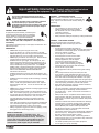
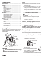
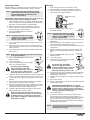
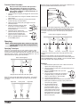
1
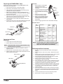
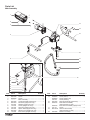
Replacing the prime/spray Valve
Gun Filter
Perform the following procedure using PRIME/SPRAY valve
replacement kit P/N 0507690.
1. Drive the groove pin out of the valve handle.
2. Remove the valve handle and the cam base.
3. Using a wrench, loosen and remove the valve housing
assembly from the pump manifold.
4. Make sure the gasket is in place and thread the new
valve housing assembly into the pump manifold. Tighten
securely with a wrench.
5. Place the cam base over the valve housing assembly.
Lubricate the cam base with grease and line up the cam
with the pump manifold using the dowel pin.
6. Line up the hole on the valve stem with the hole in the
valve handle.
7. Insert the groove pin into the valve handle and through the
valve stem to secure the valve handle in position.
Dowel Pin
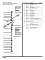
1. Pull the bottom of the trigger
guard forward so that it
Gun
comes loose from the handle
Housing
assembly.
2. Loosen and remove the handle
Filter
assembly from the gun head.
3. Pull the old filter out of the gun
Handle
head.
Seal
4. Slide the new filter, tapered
end first, into the gun head.
Handle
5. Make sure the handle seal is in
position and thread the handle
assembly into the gun head
until secure.
6. Snap the trigger guard back onto the handle assembly.
Gun Filter Chart
Pump
Manifold
Valve Housing
Assembly
Gasket
Valve Stem
Groove Pin
Valve
Handle
Application
Filter
Type
Color of
Filter
Body
0089960
Synthetic resin,
enamels, clean
varnishes, stains
azures
Extrafine
red
0089959
Base coat enamels,
primer enamels,
fillers, marking paints,
textured enamels
Fine
yellow
0089958
Emulsions,
latex paints,
acrylic paints
Medium
white
0089957
Heavy bodied latex,
blockfillers,
elastometrics
Coarse
green
Cam Base
Replacing the Filters
Pump Filter
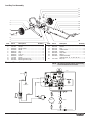
1. Loosen and remove the filter housing.
2. Pull the filter from the pump manifold.
NOTE: For more detail, part number information, and an
assembly drawing, please see the G-10 Airless
Spray Gun Owner’s Manual (P/N 0286928).
NOTE: If the filter breaks off in the pump manifold, use a
small wood screw to remove.
3. Inspect the filter seal. Based on inspection, clean or
replace the seal.
4. Push the new or cleaned filter into the pump manifold.
5. Slide the filter housing over the filter and thread it into the
pump manifold until secure.
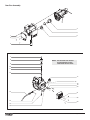
Replacing the Motor Assembly
1. Perform the Pressure Relief Procedure and unplug the
sprayer.
2. Remove the four motor cover screws. Remove the motor
cover.
3. Remove the four heat sink assembly screws. Pull the heat
sink assembly away from the gear box housing.
4. Disconnect the five wires from the relay that is mounted
on the inside of the heat sink assembly.
5. Remove the three relay mounting screws from the heat
sink assembly. Remove the relay.
6. Using the three relay mounting screws, install the new relay
onto the heat sink assembly. Tighten the screws securely.
7. Connect the five wires to the new relay (refer to the
electrical schematic in the Parts List section of this manual).
8. Using the four heat sink assembly screws, install the heat
sink assembly onto the gear box housing. Tighten the
screws securely.
9. Disconnect the black and red wires coming from the gear
box housing. Disconnect the black and red wires from the
capacitors. Disconnect the black and red wires from the
motor.
10. Loosen and remove the four motor mounting screws.
11. Pull the motor out of the gear box housing.
Filter Housing
Filter
Filter Seal
Pump Manifold
Part
Number
8
© Titan Tool Inc. All rights reserved.