1
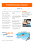
Installation, Operating,
and Service Manual
Badu Stream II
®
Counter Swimming Unit
Technical Support
Address: Speck Pumps
8125 Bayberry Road
Jacksonville, FL. 32256
USA
Hours: 8:00 am to 5:00 p.m. EST (Monday - Friday)
Toll Free: 800-223-8538
Phone: 904-739-2626
Fax: 904-737-5261
Web site: www.usa.speck-pumps.com
Manufactured by Speck Pumps, Jacksonville Florida USA, © 2012 All Rights Reserved.
This document is subject to change without notice.
Date of Installation:
Installed By:
Serial Number:
For Service Call:
2999999981 - Rev. 0412
2
ET.3.RT
Table of Contents
1
Important Safety Instructions
4
Entrapment Prevention . . . . . . . . . . . . . . 5
VGB Compliance . . . . . . . . . . . . . . . . 6
2
General Description 7
3
Installation Information
7
Preparation Guide. . . . . . . . . . . . . . . . 7
Planning. . . . . . . . . . . . . . . . . . . . 8
Dimensional Drawing . . . . . . . . . . . . . . . 8
Plumbing Installation . . . . . . . . . . . . . . . 9
Concrete or Gunite Installation . . . . . . . . . . 11
Liner and/or Fiberglass Pool Installation . . . . . . . 13
Removal of Liner . . . . . . . . . . . . . . . . 14
Pump and Control Box Installation . . . . . . . . . 15
4
Operation 15
5
Service and Maintenance 15
Nozzle Adjustments . . . . . . . . . . . . . .
15
Winterizing . . . . . . . . . . . . . . . . . . 16
6
7
Trouble Shooting 17
General Troubleshooting Problems . . . . . . . .
17
Product Specification 18
Replacement Parts and Exploded View . . . . . . . 18
8
Limited Warranty
19
3
1 Important Safety Instructions
READ THIS MANUAL CAREFULLY BEFORE USING THIS PRODUCT
Important Notice:
READ AND FOLLOW ALL INSTRUCTIONS!
This manual contains important information about the installation, operation and safe use of this product. This
information should be given to the owner and/or operator of this equipment.
WARNING: Before Installing this product, read and follow all warning notices and instructions which are included.
Failure to follow safety warnings and instructions can result in severe injury, death, or property damage. Call
1-800-223-8538 or visit www.usa.speck-pumps.com for additional copies of these instructions.
When installing and using this electrical equipment, basic safety precautions should always be followed,
including the following:
1. READ AND FOLLOW ALL INSTRUCTIONS
2. WARNING: To reduce the risk of injury, do not permit children to use this product unless they are closely
supervised at all times.
3. WARNING: All work must be preformed by a licensed electrician and must conform to all national, state, and
local codes.
4. WARNING: TO REDUCE THE RISK OF ELECTRICAL SHOCK, connect all ground wires to the grounding
terminal located in the control box. Use no smaller than a No. 12 AWG (3.3mm2) wire.
5. WARNING: TO REDUCE THE RISK OF ELECTRICAL SHOCK, a bonding connector is provided on the
motor for bonding to local ground points such as water pipes, metal ladders, metal handrails, or other metal
within 5 feet of the pool. All local ground points should be bonded with a No. 8 AWG (8.4mm2) wire. Never use
gas piping as an electrical ground.
6. DO NOT store or use gasoline or other flammable vapors or liquids in the vicinity of this equipment. DO NOT
store pool chemicals near the equipment.
8. DO NOT remove any safety alert labels such as DANGER, WARNING, or CAUTION. Keep safety alert labels
in good condition and replace missing or damaged labels.
9. WARNING: Stay alert, watch what you are doing and use common sense. DO NOT use unit if you are tired
and/or exhausted. DO NOT use unit while under the influence of drugs, alcohol, or any medications.
10. Consult your physician before exercising with the BaduStream or using the massage hose.
11. DO NOT use or operate the BaduStream if the anti-entrapment cover is missing, broken or loose.
12. Keep and read all equipment manuals. Adhere to all of their instructions. Refer to them frequently and use
them to instruct third party users.
SAVE THESE INSTRUCTIONS.
4
WARNING - Entrapment Prevention
DANGER: DO NOT BLOCK SUCTION
SUCTION HAZARD. Can cause serious injury or death. Do not use this
pump for wading pools, shallow pools, or spas containing bottom drains,
unless pump is connected to at least two (2) functioning suction outlets.
WARNING: Pump suction is hazardous and can trap and drown or disembowel
bathers. Do not use or operate swimming pools, spas, or hot tubs if a suction
outlet cover is missing, broken, or loose.
The following guidelines provide information for pump installation that
minimizes risk of injury to users of pools, spas, and hot tubs:
Entrapment Protection: The pump suction system must provide protection
against the hazards of suction entrapment.
Suction Outlet Covers: All suction outlets must have correctly installed,
screw-fastened covers in place. All suction outlet (drain) covers must be
maintained. Drain covers must be listed/certified to the latest published
edition of ANSI/ASME A112.19.8 (ANSI/APSP-16, 2011). They must be
replaced if cracked, broken, or missing.
Number of Suction Outlets Per Pump: Provide at least two (2) hydraulicallybalanced main drains, with covers, as suction for each circulating pump
suction line. The centers of the main drains (suction outlets) on any one (1)
suction line must be at least three (3) feet apart, center to center.
The system must be built to include at least two (2) suction outlets (drains) connected to the pump whenever
the pump is running. However, if two (2) main drains run into a single suction line, the single suction line may
be equipped with a valve that will shut off both main drains from the pump. The system shall be constructed
such that it shall not allow for separate or independent shutoff or isolation of each drain.
More than one (1) pump can be connected to a single suction line as long as the requirements above are
met.
Water Velocity: The maximum water velocity through the suction fitting or cover for any suction outlet must
be 1.5 feet per second, unless the outlet complies with the latest published edition of ANSI/ASME A112.19.8
(ANSI/APSP-16, 2011), the standard for Suction Fittings For Use in Swimming and Wading Pools, Spas,
Hot Tubs, and Whirlpool Bathtub Applications. In any case, do not exceed the suction fitting’s maximum
designed flow rate.
If 100% of the pump’s flow comes from the main drain system, the maximum water velocity in the pump
suction hydraulic system must be six (6) feet per second or less, even if one (1) main drain (suction outlet)
is completely blocked. The flow through the remaining main drain(s) must comply with the latest published
edition of ANSI/ASME A112.19.8 (ANSI/APSP-16, 2011), the standard for Suction Fittings For Use in
Swimming and Wading Pools, Spas, Hot Tubs, and Whirlpool Bathtub Applications.
Testing and Certification: Suction outlet covers must have been tested by a nationally recognized testing
laboratory and found to comply with the latest published edition of ANSI/ASME A112.19.8 (ANSI/APSP16, 2011), the standard for Suction Fittings For Use in Swimming and Wading Pools, Spas, Hot Tubs, and
Whirlpool Bathtub Applications.
5
WARNING - Entrapment Prevention - continued
Fittings: Fittings restrict flow; for best efficiency use fewest possible fittings (but at least two (2) suction outlets).
Avoid fittings that could cause an air trap.
Pool cleaner suction fittings must conform to applicable International Association of Plumbing and Mechanical
Officials (IAPMO) standards.
VGB Compliance
The Virginia Graham Baker Pool Safety Act promotes the safe use of pools, spas, and hot tubs by imposing
mandatory federal requirements for suction entrapments avoidance. The Act, which is being administered
by the U.S. Consumer Product Safety Commission (CPSC) and became effective December 19, 2008, is an
extension of the ASME standard which regulates Safety Drain Covers, Public Pool Drain Systems, and SwimJet
Combination Fittings. The VGB Pool Safety Act compliance relies on the ANSI/ASME A112.19.8 (ANSI/APSP16, 2011) code for proper testing and certification of the fittings. The only addition is the requirement to exhibit
VGB nomenclature on the actual fitting.
The Speck SwimJet Combination Fittings are certified by MET, a Nationally Recognized Testing Laboratory
(NRTL) to the ANSI/ASME A112.19.8 (ANSI/APSP-16, 2011) Standard, bearing the VGB nomenclature and are
compliant with the VGB Pool Safety Act.
As a condition of the listing, all Speck Badu SwimJet Systems comply with the ANSI/APSP-7 Standard for
Suction and Entrapment Avoidance. This standard is designed to avoid all five suction entrapment hazards: hair
entrapment, limb entrapment, body suction, evisceration/disembowelment, and mechanical entrapment.
All Speck Badu SwimJet Systems are certified by MET to the ANSI/ASME A112.19.8 (ANSI/APSP-16, 2011)
Standard and are defined in the standard paragraph 1.1.6:
1.1.6.4 Swim Jet Combination Fittings. All swim jet combination fittings that combine suction and
discharge into one housing, creating a high velocity, high volume stream of water to swim, jog, or
walk against, as well as massage, shall be considered “Swim Jet Combination Fittings”.
NOTE: There are four types of Suction Fittings that are defined in the ANSI/ASME A112.19.8 (ANSI/APSP-16,
2011) Standard for Suction Fittings for use in Swimming Pools, Wading Pools, Spas, and Hot Tubs. They are:
Field Fabricated Outlets, Venturi Outlets, Swim Jet Combination Fittings and Submerged Suction Outlets.
WARNING - Risk of Electrical Shock or Electrocution
This pool pump must be installed by a licensed or certified electrician or a
qualified pool serviceman in accordance with the National Electrical Code and all
applicable local codes and ordinances. Improper installation will create an electric
hazard which could result in death or serious injury to pool users, installers, or
others due to electrical shock, and may also cause damage to property.
Always disconnect power to the pool pump at the circuit breaker before
servicing the pump. Failure to do so could result in death or serious injury to
serviceman, pool users, or others due to electric shock.
6
2 General Description
Badu®Stream II
The Badu SwimJet Systems from Speck Pumps are designed to be installed during the construction of your pool
to create a water treadmill for anyone wanting a therapeutic and effective exercise.
The Badu SwimJet Systems can be installed in any type pool, large or small, from gunite to vinyl liner. It has no
protruding parts ensuring pool user’s safety, is very compact and installs at minimal cost. The self-contained,
flush-mounted unit is a jet-propulsion system that pumps water into the pool creating a current in excess of 5,700
gallons per minute from a single recessed jet housing.
Topping off the experience is the pulsating massage hose which can be attached to the jet nozzles for easy and
convenient massage treatments for joints and muscles. (NOTE: The massage hose is sold separately.)
3 Installation Information
Preparation Guide
1. Upon receipt of the swimjet system, check the cartons for damage. Open the carton and check the pump (F),
jet housing (A), and control box (E) for concealed damage, such as cracks, dents, or a bent base. If damage is
found, contact the shipper or distributor where the swimjet was purchased.
2. Inspect the contents of the carton and verify that all parts are included. All parts are manufactured of corrosionresistant material and combined in one single housing (two or three single housings for multi jet systems) which
can be installed in pools of any size and shape. (See Figure 1)
A. Flush mounted Jet Housing
D
B. Square, Anti-Entrapment Cover (81/4” x 81/4”)
undetectable pump suction. (Optional Round
Cover)
C. Adjustable Water Flow Jet Nozzle
D. Air Regulator adjusts amount of air bubbles
in water flow.
E. Control Box with GFCI pneumatic button and
tubing.
F
B
C
A
G
E
Figure 1
F. Speck 4 HP or 3.5 HP self-priming, plastic pump, single phase with thermal overload (no motor starter
required). Optional three phase motor and control box available. (NOTE: Normal priming pump available
for installation below water level.)
G. Optional Massage Hose with pulsator may be attached to jet nozzle.
7
Planning
The BaduStream is normally incorporated into the original pool design. However, it can be added to any pool at
a later date.
The BaduStream has no protruding parts, ensuring the pool user’s safety. It is very compact and installs at
minimal cost.
The BaduStream can be installed in any size pool. We suggest a minimum pool size of 7 ft. wide, 14 ft. long
and 31/2 ft. deep in order to swim. Most swimmers prefer 16 ft. in length or longer. The extra length allows the
swimmer to comfortably drift back and swim up stream. The BaduStream is complete with jet housing, 4 HP or
3.5 HP pump, control box, and optional massage hose. The only additional requirement is the plumbing. (4” pipe
for 4 HP and 3” pipe for 3.5 HP units.) Consult local codes for minimum distance between pump and pool. Locate
pump as close to the BaduStream as practical.
Use at least 4” pipe when distance between jet housing and pump is 30 ft. or less and 6” for pipe runs
longer than 30 ft.
The 4 HP, self-priming, plastic pump has a single phase motor with thermal overload (no motor starter
required). The 4 HP single phase motor draws a maximum of 19.4 amps @ 230V. The unit requires a
minimum circuit of 30 amps. Install a 40 amp breaker to avoid nuisance tripping when pump is turned on
and off frequently. The starting current of the 4 HP motor can reach up to 6 times the running currents.
(Three phase motor draws a maximum of 12.8 amps @ 230V and 6.4 amps @ 460V.) The 3.5 HP single
phase motor draws 13.6 amps @ 230V.
9.25"
3.25"
0.79 "
4.49"
4.92 "
4.72 "
5.59 "
8.27 "
7.32 "
6.54 "
1.97"
"
4.
92
4.
49
"
"
97
1.
Figure 2
BaduStream dimensional drawing
8
Plumbing
The BaduSteam assembly package contains all necessary parts for the installation of the unit into concrete,
gunite, liner or fiberglass pools.
PLUMBING REQUIREMENTS
BADUSTREAM II
Pump
Distance
Pipe Size
Approx. flow
Pressure
Three Jets
(2) 4 HP
10 to 30 ft.
up to 50 ft.*
4”
6”
700 GPM
700 GPM
16 PSI
16 PSI
Two Jets
4 HP
10 to 30 ft.
up to 50 ft.*
4”
6”
380 GPM
400 GPM
14 PSI
14 PSI
One Jet
4 HP
10 to 30 ft.
up to 50 ft.*
4”
4”
270 GPM
260 GPM
18 PSI
18 PSI
One Jet
3 HP
10 to 30 ft.
up to 50 ft.*
3”
4”
200 GPM
200 GPM
12 PSI
12 PSI
Maximun 4 Feet
Water Level
Service
Disconnect
4"
Pump
Vertical
Discharge Line
4"
Horizontal
Discharge Line
10"
Minimum
2"
Air Regulator
Allow 12" to prevent
cavitation of the pump
6 " Riser
* 6” pipe will allow distances of well over 50 ft.
However, control box needs to be within 50 ft. for the
pneumatic on/off button to function properly.
Control Box
Pressure Line
Valves (Optional)
4"
4"
4"
Check Value (Optional)
(Below Water Level)
Vertical Suction Line
NOTE: Valves are recommended when pump
is installed below water level.
NOTE: Encase jet housing and at least 2 to 3
inches of plumbing with concrete.
Horizontal Suction Line
max. 30 feet with 4 " pipe
Figure 3
CAUTION: All necessary screws and bolts included with the BaduStream are stainless steel. ALL screw
threads and threaded inserts are METRIC! ONLY METRIC bolts and nuts may be used! The two exceptions
are the intake and delivery connections on the BaduStream and pump housing and the hardware for the air
regulator assembly. The intake and delivery connections on the pump model 21-80 are 4” Slip (3” Slip on
pumps Model 72). The air regulator assembly hardware is US standard thread.
CAUTION: The center of the housing (the nozzle) should be 10” BELOW water level for maximum efficiency. The
air regulator should be approximately 4” (or minimum 2”) ABOVE the water level. (See Figure 3)
CAUTION: When connecting the pressure line into the pressure connection on top of the 4 HP pump Model
21-80, first install a 6” (15 cm) riser (See Figure 3) before installing an elbow and leading the pressure line
downward to the pressure connection at the jet housing. This will guarantee trouble-free priming of the pump.
(Not required for the 3.5 HP Model 72)
CAUTION: When using 6” pipe the suction line should run to a point directly under the pump and up to the water
line in 6” and finish vertical and elbow into the pump in 4” to minimize priming time. (See Figure 3)
CAUTION: In areas with soft soil conditions or with frequent earth movement, a flexible section of hose should
be attached to the back of the jet housing to prevent housing breakage.
CAUTION: Throughout the entire installation, make sure the plumbing connected to the BaduStream housing
is well supported. Unsupported plumbing will crack the housing.
9
Plumbing - continued
4"
4"
BaduStream Single Housing Installation
Elb
ow
m
Fro mp
u
P
Elb
ow
To p
m
Pu
4"
4"
e
Pip
e
Pip
4"
4"
Figure 4
Elb
ow
Pip
BaduStream Dual Housing Installation
e
45
4"
4"
4"
Elb
ow
Pip
e
Te
e
4"
m
Fro mp
Pu
4"
e
Pip
e
Pip
4"
4"
ipe
"P
Elb
ow
4
Figure 5
To p
m
Pu
P
4"
4"
ipe
4"
Elb
ow
2
om #
Fr mp
u
P
4"
45
NOTE: (For Dual and Triple Jet Installation)
Increase the pipe size to 6” when jets are more
than 30 ft from the pump. Use 6” x 4” bushings
after 4” manifold tees.
4"
4"
Figure 6
4
BaduStream Triple Housing Installation
10
4"
e
Pip
Pip
e
4"
e
Pip
4"
e
Pip
4"
e
Pip
4"
ipe
"P
To # 2
mp
ipe
Pu
"P
4"
4"
To # 1
mp
Pu
Pip
e
4
4"
4"
Te
e
Te
e
Te
e
om 1
Fr
#
mp
Pu
"
18
" to ter
10 Cen
on
45
Pip
e
4"
4"
Pip
e
4"
Elb
o
w4
5
Elb
o
w4
5
Elb
o
w4
5
Pip
e
8"
1
r
o
" t ente
0
1 C
on
Pip
e
8"
1
r
o
" t ente
0
1 C
on
Pip
e
NOTE: CHECK VALVES must be used on the
discharge side of each pump. Minimum 4” pipe
between pump and BaduStream plumbing
manifold.
Concrete or Gunite Installation
1. Pre-plumb BaduStream housings:
A. Install plumbing manifold or approximately 12” of 4” SCH 40 pipe to both suction and discharge
fittings on the jet(s) housing. NOTE: If plumbing exceeds 30’ between jet housing and pump, increase
pipe size to 6”. Install a 6” x 4” reducing bushing as close to jet housing as possible.
B. Install air control PVC hose to hose socket insert fittings (part #6). Use hose clamps to secure hose
to insert fittings.
2. Tape the jet housing keep concrete out of threaded inserts and out of the inside of the housing.
3. Place jet housing into reinforced steel. Jet housing location is very important.
A. Locate air control hose connector (part #6) at the top and center of jet housing. Air control hose
connectors must be vertical or the square cover will be uneven in appearance.
B. The center of the housing (the nozzle) should be 10” BELOW water level for maximum efficiency.
C. Front edge of jet housing should finish even with inside gunite wall. Make sure a V shaped groove is
scraped out around the housing approximately 11/2” deep to allow marcite to seal against the housing.
DO NOT disassemble jet nozzle from housing.
D. Recheck location of the jet housing when gunite is being applied. The force of the gunite may move
the jet location.
E. To avoid stress on the jet housing, we recommend that the BaduStream housing be encased with
gunite and at least 2 to 3 inches of the plumbing stub out is covered with gunite.
NOTE: Stress on the plumbing may crack the BaduStream housing.
4. Air regulator installation should be approximately 4” (or minimum 2”) ABOVE the water level.
A. Air regulator holder and hose socket insert fitting connect to PVC hose. Make sure air regulator
holder face is tapped over to prevent gunite from entering holder.
B. Air regulator can be located in the tile line above water line or in the deck. When tiling the pool, adjust
the air regulator holder to proper positioning 4” (or minimum 2”) ABOVE the water level. Place and
set with hydraulic cement. Install air regulator flush with the inside pool wall. Drill a 1/2” hole in the tile
even with the center hole on the air regulator. Then tile over the air regulator holder (part#17). Note:
Be sure NOT to plug the center hole of the air regulator holder with thinset or the tile.
C. Install the air regulator sub-assembly.
1. Top Part
Part# 22
2. Bottom Part
Part# 23
3. Screw M10 x 80
Part# 24
4. Hose Ring - 16 x 30 x 80
Part# 25
5. Gasket - Air Control 42 x 11 x 2 Part# 26
19
20
17
D. To install the bottom parts of the sub assembly,
a flat head screw driver is required to tighten
the screw to the holder.
(Make sure the air regulator holder is free of
debris or the screw (part #24) will not screw in
properly.)
18
21
26
23
24
Figure 7
18
25
22
Air Regulator Assembly
11
Concrete or Gunite Installation - continued
Note: Make sure the gasket (part #26) is on the back side of the bottom part (part
#23) against the tile. This will keep the parts secure to the tile.)
E. Install the top part (part #22). Snap the top part to the bottom part (part #23) and
turn clock wise until you hear it ratchet. Turn clock wise to adjust the air.
5. When installing the BaduStream Cover (part #8). Use a Phillips head screw driver and tighten to 1.5 Nm or
hand tight.
6. Keep all parts not being used now in original box. Store in a safe place until needed.
An extension ring is available (upon request) for an application that has special needs.
6. The following is a list of all parts that ARE NOT USED IN A GUNITE INSTALLATION:
1. Gasket - Clamping Ring
2. Bolt - 1/4-20 x 1-1/2”
3. Nut - 1/4-20
4. Washer 1/4”
5. Gasket 60 x 11 x 2
6. Screw - Jet Housing 14 X 1”
Part# 12
Part# 18
Part# 19
Part# 20
Part# 21
Part# 27
Deck
Air Regulator
Tile
2" Minimum
Water Level
Air Line
Concrete
Wall
10"
Pressure
Housing
Fitting 4"
Pipe
Suction
Fitting 4"
45 Elbow
Plaster
Figure 8
Template for Installation in Gunite or Concrete Pools.
Figure 9
BaduStream in Concrete or Gunite Pool.
Liner and/or Fiberglass Pool Installation
1. Using the clamping ring (part #3) as a template, drill holes in the pool wall for installation. The center line of the
clamping ring should be 10” below the surface of the water. (See Figure 8) Two additional holes need to be drilled
at the 3 and 9 o’clock positions for installation of the housing (part #7). The four brass inserts in the clamping ring
should be at the 2, 4, 8 and 10 o’clock positions.
12
Liner and/or Fiberglass Pool Installation - continued
2. Mount the housing (part #7) and one gasket (part #12) on the outside of the pool wall using two screws 14 x 1”
(part #27). Install the screws from the inside of the pool wall through the holes drilled at 3 and 9 o’clock positions.
(See Figure 10 & 11)
3. Install the clamping ring (part #3) and the gasket (part #12) on the inside of the pool wall using eight screws
(part # 9/2, 9/3, 9/4, or 9/5) Screw lengths vary depending on the installation.
A. A good RTV silicone may be used with the gasket when mounting the jet housing, but in most cases
is not necessary. Installer should decided whether or not the silicone is necessary.
B. When installed properly, the center of the housing (part #7) will be 10” below the surface of the water
and the hose connector 1/4” (part #6) will be at the top center of the jet housing.
C. When installing the BaduStream Cover (part #8). Use a Phillips head screw driver and tighten to 1.5
Nm or hand tight. (NOTE: The square cover, part #8, will have an uneven appearance if the housing
is not installed properly.)
4. For the air regulator assembly, one 1/2” hole must be provided, preferably along the vertical axis, approximately
4” (or minimum 2”) ABOVE the water line. (See Figure 10 & 11). Using the air regulator assembly gasket (part
#21), mark and drill two 1/4” mounting holes. (See Figure 10) Use two flat head 1/4 - 20 machines screws (part
#18) and two 1/4-20 nuts (part #19) to mount the air regulator. (NOTE: The flat head on the inside of the pool wall
and the nut on the outside of the pool wall.)
5. Keep all parts not being used now in original box. Store in a safe place until needed.
For Liner Pools Only: Install the jet housing and air regulator prior to installation or replacement of the pool liner.
For Steel Walled Pools: An optional butterfly gasket (part #12A) maybe purchased to replace the two gaskets
(part #12). Increase the jet housing hole from 5.59” to 5.75” for installation. (See Figure 10)
Deck
Air Regulator
2" Minimum
Water Level
Air Line
10"
Pressure
Housing
Fitting 4"
Pipe
Suction
Fitting 4"
45 Elbow
Liner &
Wall
For Liner & Fiberglass Pools Only
Figure 10
Cutout Pool Wall for BaduStream housing.
Figure 11
BaduStream in Liner or Fiberglass Pool.
13
Removal of Liner
When replacing liner or removing liner for repairs; remove 4 screws (part #9/1) which hold the square cover
(part #8) to the jet housing. Remove all screws (part #9/2 & 9/3) except the top two, which hold the clamping
ring (part #3) and gasket (part #12) to the jet housing. Back out the two remaining screws approximately halfway
and check for any movement of the jet housing from the wall. (NOTE: If the two counter sunk screws (part #27)
which hold the jet housing to the wall were installed, the jet housing should not move, and the two remaining
screws can be removed.) Remove one of the remaining two screws and slide the clamping ring (part #3) to the
side. Replace all the screws before removing the last screw. Remove or replace the liner. Reverse the process
to install liner.
NOTE: When replacing the clamping ring and screws: locate screw heads under liner, make a small cut on the
liner at the screw heads and push the liner over the screw head.
Pump and Control Box Installation
CAUTION: Before installing the Speck Pump, read the entire pump owner’s manual found in the pump box.
Consult local codes for minimum distance between pump and pool. Locate pump as close to the pool as practical.
The air button works up to a maximum of 50 ft. There is 50 ft. of air tubing in the BaduStream box.
WARNING: To reduce the risk of injury, do not permit children to use this product unless they are closely
supervised at all times.
The wiring of the pool motor and control box should be done by a licensed electrician in accordance with local
codes. Be certain that the motor frame and control box are grounded. Motor name plate has voltage, phase, amp
draw, and other motor information as well as wiring connection instructions.
BONDING: As required by National Electrical Code Article 680-22, the pump motor must be electrically bonded
to the pool structure (reinforced bars, etc.) by a solid copper conductor not smaller than No. 8 AWG via the
external copper bonding lug on the pump motor.
GROUNDING: Permanently ground the pump motor and control box using a conductor of appropriate size.
Connect to the No. 10 green headed ground screw provided inside the motor terminal box.
NOTE: Do not connect to electric power supply until the unit is permanently grounded.
Section 8 concerns the electric motor and control box only since all other parts, the pump, the jet unit, etc. have
complete and absolute separation from the pool water.
4 Operation
Operation
Remove the red filler plug or strainer tank lid on the pump and fill the pump with water. Replace the red filler plug
or lid. Push pneumatic button on. For the first start-up allow approximately 5 minutes for the pump to prime. If
the pump has not started priming after 5 minutes, the amount of water in the pump was not sufficient. Add more
water. Due to the large volume of air that can be present in the vertical portion of the suction above the waterline,
initial priming time may be longer than with regular pool filtration pumps. It may take up to 10 minutes. This will
not damage the mechanical seal.
14
Operation - continued
WARNING: Do not use or operate the BaduStream if the anti-entrapment cover is missing, broken, or
loose.
To start swimming, jogging or running it is suggested that the two nozzles are pointed slightly inward and
slightly upward so that the water “breaks” approximately 4 ft. in front of the BaduStream. (See Section 5 Nozzle
Adjustment to properly adjust the nozzles.) Start swimming with only minimal force in arms an legs until you feel
yourself drifting backwards, then add force and swim upstream until a proper balance is found between force
and endurance.
Keep in mind that this unit is designed for a balanced workout. Find a pace that you can keep up for at least 20
minutes. Out pacing is always possible. The idea is to continue exercising for an extended period of time.
Consult your physician before attempting any strenuous exercise. This product may not be challenging
or satisfying for all levels of exercise.
The air regulator permits a controlled mixture of air into the water flow and creates a unique, invigorating, bubble
bath effect. It will also add additional resistance to swim against.
The BaduStream’s adjustable flow nozzle(s) enables the swimmer to regulate the volume of water released
through the jet(s). Turning the nozzle clockwise reduces the flow. The swivel nozzle(s) of the BaduStream can
be positioned in various directions, allowing swimmers to use various swim styles.
Optional Accessory: The Badu Swim Mirror is a
perfect addition to the BaduStream, this portable mirror
is designed to be the perfect tool to help swimmers
stay in the “swim lane”.
Optional Accessory: A pulsating massage hose can
be attached to one of the nozzles to enjoy a massage
as advised by your physician. (See Figure 1 Letter G)
Directions for use: Consult your physician before
using the massage hose. To reduce the risk of injury,
do not permit children to use the massage hose with
pulsator unless they are closely supervised at all times.
Close the air regulator. Reduce the volume of water by
turning the adjustable flow nozzle(s) clockwise.
Under certain conditions it is possible that the current
“drifts off” to the left or to the right from the middle due
to water bouncing off the back wall. In the event that
this interferes with your swimming action, turn unit off
for a few minutes and restart.
Figure 12
Badu Swim Mirror
5 Service and Maintenance
Nozzle Adjustment
When setting the nozzles for basic swimming, it is recommended that you set the nozzles in such a way that each
nozzle(s) intersects 4 feet away while at the same time breaks the surface.
15
Nozzle Adjustment - continued
To help set the nozzles in a neutral position, please follow these instructions:
1. Parts required:
Quantity 2 - 4’x1 1/2” PVC Pipe
Quantity 2 - 1 1/2” MPT x 1 1/2”/1 1/4” Hose Adaptor
Quantity 2 - Female Adapter 1 1/2” Slip x 1 1/2” FPT
2. Turn off the jet pumps
3. Insert each jet adjustment tool into jet nozzle.
4. Move each jet adjustment tool toward each other until each pipe touches at water level.
5. Remove jet adjustment tool.
Hose Adapter 1 1/2” x 1 1/4” Tapered
Figure 13
BaduStream Nozzle Adjustment
Winterizing
In areas subject to freezing water temperatures, you should protect your equipment. We recommend you
purchase a winter cover kit part #2308752006K. This kit includes 1 winter plate, 1 gasket and 4 screws.
Also, you can protect your swimjet system as follows: Drain pool until water level has dropped below the antientrapment cover. Then protect pump by removing drain plug and red filler plug (or lid).
16
6 Troubleshooting
Frequently Asked Questions
How is the current generated?
The pump generates up to 400 GPM coming out of two
jet nozzles at 27 ft. per second and 36 ft. per second
thru one nozzle creating a swim current in excess of
5000 GPM, measured 6 ft. from the jet.
What size pool do I need?
The BaduStream can be installed in any size pool.
However, we recommend a minimum length of 14’ and
a minimum width of a 7 foot swimming lane.
What size plumbing is necessary? How far away
from the BaduStream can the pump be installed?
Use 4” plumbing up to 30’. For runs longer that 30’ use
6” plumbing. The pump can be placed as close to the
BaduStream as local codes will allow.
How many amps does the pump operate at?
4 HP: Maximum 19.4 amps @ 230 V
3.5 HP: Maximum 13.6 amps @ 230 V
What size breaker do I need?
You must use a 40 amp breaker for the 4 HP pump or
30 amp breaker for the 3 HP pump to avoid nuisance
tripping.
Is the BaduStream approved?
Yes. The BaduStream swim jet system is listed by
MET and complies with UL standard 1563 Swimming
Pool Equipment, ASME standard ANSI/ASME
A112.19.8 (ANSI/APSP-16, 2011) Standard for Swim
Jet Combination Fittings, and is VGB 2008 compliant.
Does it matter if the housing is installed higher or
lower than the manual states?
Yes, the center of the jet must be 10” BELOW
estimated water level for proper performance of unit.
Can the air regulator be placed elsewhere?
Yes, as long as it is not continuously flooded with
water.
Can the pump be placed below water level?
Yes. However, for best performance we recommend
ordering pump for flooded suction (Model 21-80/33G)
instead of self-priming (Model 21-80/33GS). We
recommend installing valves for ease of maintenance.
How far away can the air button function properly?
A maximum of 50 ft. Consult factory for distances over
50 ft.
Do I need to install a motor starter?
No. The pump has a built-in thermal overload.
Should this be tied into my filter system?
No. The swim jet system and the filter system should
not be plumbed together as they each provide very
specific functions.
Can I use with automated controls?
Yes. It comes with the ability to tie into automated
control systems or other switching devices.
Do the covers come in different colors?
Yes. The round covers can be ordered in gray or black.
The square cover is only available in black or white.
Does the air regulator come in different colors?
Yes. The air regulator can be ordered in black.
17
7 Product Specification
16
14
19
15
20
17
16
18
21
26
6
5
23
24
18
25
22
7
11/2
11/1
10
4
27
13
Part #
1
2
3
4
5
6
7
8
9/1
9/2
9/3
9/4
9/5
10
11/1
11/2
12
12A
13
(14 - 21)
14
15
16
17
18
19
20
21
18
Qty
1
6
1
1
1
1
1
1
4
8
8
8
4
1
1
2
2
1
1
1
1
1
2
1
2
2
2
1
1
9/2
9/3
9/4
9/5
2
Description
Face Ring - Nozzle
Screw - Tapping 5.5 x 19
Clamping Ring
Nozzle (adjustable flow)
Bushing
Hose Connector 1/4”
Housing
Square Cover
Screw - M6 x 25
Screw - M6 x 20
Screw - M6 x 25
Screw - M6 x 40
Screw - M6 x 45
Seat - Nozzle
Spacer Ring - 6.2
Spacer Ring - 4
Gasket - Clamping Ring
Gasket - Butterfly (not shown)
Gasket - Face Ring
Holder w/ Hose Subassembly
Hose Fitting - 1/4”
Hose - 8 x 3
Hose Clamp 14/9
Holder - Air Regulator
Screw - 1/4-20 x 1-1/2”
Nut - 1/4-20
Washer - 1/4”
Gasket 60 x 11 x 2
12
12
3
8
9/1
Part #
(22-26)
22
23
24
25
26
27
Qty
1
1
1
1
1
1
2
*1
Description
Subassembly Complete
Top Part - Air Regulator
Bottom Part - Air Regulator
Screw - Air Regulator M10 x 80
Hose Ring - Air Regulator 16 x 30 x 80
Gasket - Air Control 42 x 11 x 2
Screw - Jet Housing 14 x 1”
Extension Ring (pre-glued) (not shown)
Optional Winter Cover Kit:
Part #
12
9/1
Qty
1
4
1
Description
Gasket - Clamping Ring
Screw - M6 x 25
Winter Plate (not shown)
* Extension Ring
An extension ring (not shown) is available upon request.
8 Limited Warranty
The manufacturer supplies a limited warranty to the
original consumer purchaser of the BaduStream on
the following terms and conditions:
1. The BaduStream is warranted to be free from
defects in material and workmanship for a period of
twelve (12) months from the date that the BaduStream
is originally installed.
2. Not withstanding any provisions herein to the
contrary, the warranties and obligations hereunder
shall not in any event extend for more than 2 years
beyond the date of shipment of the BaduStream from
Speck Pumps - Pool Products, Inc. in Jacksonville,
Florida.
3. Warranty is void in the following cases: damages
which result in whole or in part from: (a) careless or
improper installation of the BaduStream; (b) improper
or negligent use and maintenance of the BaduStream;
(c) tampering with the BaduStream by unauthorized
repair personnel; (d) ground movement; (e) substitution
of parts and/or components.
4. The manufacturer’s sole obligation hereunder shall
be to replace or repair any defective BaduStream. The
manufacturer reserves the absolute right to determine
whether any defective BaduStream should be replaced
or repaired.
5. Any customer who wishes to make a claim under
this Limited Warranty shall notify Speck Pumps, of
such claim by telephone or by mail. After the customer
has been authorized to return the BaduStream, the
customer must return the BaduStream to Speck
Pumps.
Any goods returned to Speck Pumps without prior
authorization will be returned to the shipper unopened.
Speck Pumps shall not bear any costs or risks incurred
in shipping a defective BaduStream to Speck Pumps
or in shipping a repaired or replaced BaduStream to a
customer.
6. Speck Pumps will charge customers for all non
warranty work which it may perform. Non-warranty
work will not be performed until the customer has
accepted the price quoted.
7. Except as specifically set forth above, no other
warranties, whether express or implied, including
without limitation, the implied warranties of
merchantability and fitness for a particular purpose,
are made by the manufacturer. In no event will the
manufacturer be liable for any loss, including time,
money, goodwill, lost profits and consequential
damages based on contrast, tort or other legal theory,
which may arise hereunder or from the use, operation
of modification of the pump, motor or associated parts.
The maximum liability of the manufacturer hereunder
shall not exceed the amount actually paid by the
customer for the pump, motor and associated parts.
8. Some states do not permit limitations on the terms
of implied warranties or on the recovery of incidental
or consequential damages. Accordingly, the limitations
contained in paragraph 7, may not apply to certain
customers.
9. This warranty gives customers specific legal rights
which may vary from state to state. The BaduStream
is manufactured under license from Speck Pumpen,
GERMANY.
19