1
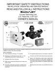
IMPORTANT SAFETY INSTRUCTIONS
INSTALLATION, OPERATING AND SERVICE MANUAL
READ AND FOLLOW ALL INSTRUCTIONS
Counterstream Swimming Unit
U.S. Patent No. 3.977.027
OWNER’S MANUAL
The Speck
Complies with UL 1563
Swimming Pool Equipment
Listing #E212148
D
F
B
C
A
G
E
This is the
All parts are manufactured of corrosion-resistant material and combined in one single
housing (or two single housings for two jet systems) which can be installed in pools of
any size and shape.
Key to illustration:
A. Flush mounted Jet Housing
B. Square, anti-vortex cover (8 1/4" x 8 1/4") for
undetectable pump suction
C. Adjustable Water Flow Jet Nozzle
D. Air regulator adjusts amount of air bubbles in
water flow
E. Control box with GFCI with pneumatic button
and tubing.
F. Speck 4 HP or 3.5 HP self-priming, plastic
pump, single phase with thermal overload (no
motor starter required). Optional three phase
motor and control available (Normal priming
pump available for installation below water
level).
G. Optional massage hose with pulsator may be
attached to jet nozzle.
TABLE OF CONTENTS
1.
Important Safety Instructions ..............................................................Page 3
2.
Introduction to Planning ......................................................................Page 3
3.
Plumbing for BaduStream ..................................................................Page 4
4.
Concrete or Gunite Installation ..........................................................Page 5
5.
Liner and/or Fiberglass Pool Installation ............................................Page 6
5a.
Removal of Liner ................................................................................Page 7
6.
Plumbing Suggestions ........................................................................Page 7
7.
Installation of the Pump and the Control Box ..................................Page 8-9
8.
Operation Instructions ........................................................................Page 9
9.
Winterizing ........................................................................................Page 10
10.
Frequently Asked Questions ............................................................Page 10
11.
Parts List for Badustream..................................................................Page 11
12.
Limited Warranty ..............................................................................Page 12
IMPORTANT INSTALLATION TIPS IN BOLD PRINT
2
1 . Important Safety Instructions
When installing and using this electrical equipment, basic safety precautions should always be
followed, including the following:
G. DO NOT store or use gasoline or other flammable vapors or liquids in the vicinity of this
equipment. DO NOT store pool chemicals near
the equipment.
!
A. READ
AND FOLLOW ALL INSTRUCTIONS.
B. ! WARNING : To reduce the risk of injury, do not
permit children to use this equipment unless
they are closely supervised at all times. Failure
to adhere to this and all other warnings could
result in serious injury or death.
!
C. A licensed electrician is required for all
wiring connections.
!
WARNING
!
D . TO R E D U C E R I S K O F E L E C T R I C A L
SHOCK, connect all ground wires to grounding
terminal located in the
! control box. Use no
smaller than a No. 12 AWG (3.3 mm2) wire.
!
E. TO REDUCE RISK OF ELECTRICAL
SHOCK, a bonding connector
is provided on the
!
motor for bonding of local ground points such as
water pipes, metal ladders/handrails, or other
metal within 5 feet of the pool. All local ground
points should be bonded with a No. 8 AWG (8.4
mm 2) wire. Never use gas piping as an electrical ground.
F. All electrical equipment should be installed
in accordance with local codes.
H. DO NOT remove any safety alert labels
such as DANGER WARNING, or CAUTION.
Keep safety alert labels in good condition and
replace missing or damaged labels.
I. Keep and read all equipment manuals. Adhere
!
to all
of their instructions.
J. ! WARNING : Stay alert, watch what you are
doing and use common sense. DO NOT use unit
if you are tired and/or exhausted. Do not use unit
while under the influence of drugs, alcohol, or
any! medication.
K. ! WARNING : Consult your physician before
exercising with the
or using the
!
massage
hose.
L.
WARNING
: DO NOT use or operate the
if the square, anti-vortex cover is
missing, broken or loose.
!
M. SAVE THESE INSTRUCTIONS! Refer to
them frequently and use them to instruct third
party users.
2. Introduction and Planning
The
is normally incorporated into
the original pool design. However, it can be
added to any pool at a later date.
Consult local codes for minimum distance
between pump and pool. Locate pump as close
to the
as practical.
The
has no protruding parts,
ensuring the pool user’s safety. It is very compact and installs at minimal cost.
Use at least 4" pipe when distance between
jet housing and pump is 30 ft. or less and 6"
pipe for runs longer than 30 ft.
The
can be installed in any size
pool. We suggest a minimum pool size of 7 ft.
wide, 14 ft. long and 3 1/2 ft. deep in order to
swim. Most prefer 16 ft. in length or longer. The
extra length allows the swimmer to comfortably
drift back and swim up stream. The
is complete with jet housing, 4
HP or 3.5 HP pump, control box, and optional
massage hose. The only additional requirement
is the plumbing. (4" pipe 4 HP and 3" pipe for 3
HP units.)
The 4 HP, self-priming, plastic pump has a
single phase motor with thermal overload
(no motor starter required). The 4 HP single
phase motor draws a maximum of 19.4 amps
@ 230 V. The unit requires a minimum circuit
of 30 amps. Install a 40 amp breaker to avoid
nuisance tripping when the pump is turned
on and off frequently. The starting current of
the 4 HP motor can reach up to 6 times the
running currents. (Three phase motor draws
a maximum of 12.8 amps @ 230 V and 6.4
amps @ 460 V.) The 3.5 HP single phase
motor draws 13.6 amps @ 230 V.
3
3. Plumbing for
PLUMBING REQUIREMENTS
Pump
Distance
Pipe Size
Approx. flow
Pressure
(2) 4 HP
10 to 30 ft.
up to 50 ft.*
4”
6”
700 GPM
700 GPM
16 PSI
16 PSI
Two Units
4 HP
10 to 30 ft.
up to 50 ft.*
4"
6"
380 GPM
400 GPM
14 PSI
14 PSI
One Unit
4 HP
10 to 30 ft.
up to 50 ft.*
4"
6"
270 GPM
260 GPM
18 PSI
18 PSI
One Unit
3 HP
10 to 40 ft.
up to 50 ft.*
4"
6"
200 GPM
200 GPM
12 PSI
12 PSI
Three Units
* 6" pipe will allow distances of well over
50 ft. However, control box needs to be
within 50 ft. for the pneumatic on/off
button to function properly.
Fig. 1
!
The BADUSTREAM assembly
package contains all
necessary parts for the installation of the unit into
concrete, gunite, liner or fiberglass pools.
CAUTION : All necessary screws and bolts included
with the BADUSTREAM are stainless steel or plas!
tic.
ALL screw threads and threaded inserts are
METRIC! ONLY METRIC bolts and nuts may be
! are the connecting thread
used! The two exceptions
for the intake and delivery connections on the
BADUSTREAM and pump housing and the hardware
!
for the air regulator assembly.
The intake and delivery
connections on the pump model 21-80 are 3" NPT
threads and 4" slip (3” on pump model 98). The air
regulator assembly hardware is US standard thread.
!
T h e c e!n t e r o f t h e h o u s i n g ( t h e
nozzle) should be 10" BELOW water level for
!
maximum
efficiency. The air regulator should be
approximately 4" ABOVE the water level. (See fig.
3.)
!
4
CAUTION :
!
CAUTION
:When connecting the pressure line to the pressure
!
connection
on top of the 4 HP Pump Model 21-80,
first install a 15 cm (6") riser (fig. 1) before installing
an elbow and leading the pressure line downward to
the pressure connection at the jet housing. This will
guarantee trouble-free priming of the pump. (Not
required for the 3.5 HP Model.)
!
CAUTION
: The suction line should run below water level right
!
up to the pump location.
!
CAUTION
: In areas with soft soil conditions or with frequent
!
earth
movement, a flexible section of hose should be
attached to the back of the jet housing to prevent
housing breakage.
!
CAUTION
: Throughout the entire installation, make sure the
!
plumbing
connected to the BADUSTREAM housing is well supported. Unsupported plumbing will
crack the BADUSTREAM housing.
4. Concrete or Gunite Installation
A. Preplumb
Housings
1. Install plumbing manifold or approximately 12" of 4"
SCH 40 pipe to both suction and discharge fittings on
the jet(s) housing. NOTE: If plumbing exceeds 30'
between jet housing and pump, increase pipe size to
6". Install a 6x4" reducing bushing as close to jet
housing as possible.
2. Install air control PVC hose to hose socket insert
fittings (part # 6). Use hose clamps to secure hose to
insert fitting.
B. Tape jet housing. Keep concrete out of threaded
inserts and out of the inside of the housing.
C. Place jet housing into reinforced steel. Jet
housing location is very important.
1. Locate air control hose connector (part #6) at the
top and center of jet housing. Air control hose
connectors must be vertical or the square cover
will be uneven in appearance.
2. The center of the housing (the nozzle) should be
10" BELOW water level for maximum efficiency.
4. Recheck location of jet housing when gunite is
being applied. The force of the gunite may move the
jet location.
5. To avoid stress on the jet housing, we recommend
that the
housing be encased with
gunite and at least 2 to 3 inches of the plumbing stub
out is covered with gunite. NOTE: Stress on the
plumbing may crack the
housing.
D. Air regulator installation should be approximately
4" ABOVE the water level.
1. Air regulator holder and hose socket insert fitting
connect to PVC hose. Make sure air regulator holder
face is taped over to prevent gunite from entering
holder.
2. Air regulator can be located in the tile line above
water line or in the deck.
E. Keep all parts not being used now in original box.
Store in a safe place until needed.
An extension ring (part #28) is available (upon
request) for an application that has special needs.
3. Front edge of jet housing should finish even with
inside gunite wall. Make sure a V shaped groove is
scraped out around the housing approximately 1 1/2"
deep to allow marcite to seal against the housing.
Fig. 2
Template for Installation in Gunite or Concrete Pools.
Fig. 3
in Concrete or Gunite Pool.
5
5. Liner and/or Fiberglass Pool Installation
! CAUTION
: Locate the air control hose connector
(part #6) at the top and center of the jet housing.
!
Connectors
must be exactly vertical or the square
cover will be uneven in appearance.
!
CAUTION : Center of Housing should be 10"
BELOW water level for maximum efficiency.
!
CAUTION : Clamping ring gasket (part #12) goes in
FRONT of pool wall. A good RTV silicone may be
!
used
with gasket when mounting jet housing, but in
most cases is not necessary. Installer should decide
whether or not silicone is necessary.
!
Fig. 4
Cutout in Pool Wall for
Housing
6
For Fiberglass pools only, the clamping ring (part
#3) can be used to mark and drill the holes as shown
in Fig. 4. For the air regulator, one 1⁄2" hole must be
provided, preferably along the vertical axis, approximately 4" ABOVE the water line.
For Liner pools only, two holes at the horizontal axis
of the jet housing and the two holes on the air regulator will allow both housing and air regulator to be
mounted to the pool wall before the liner is installed.
Use the two plastic M6 counter sunk bolts (part #18)
and two M6 nuts (part #19) (bolt heads on poolside
and nuts on backside) to mount the air regulator and
two screws (part #27) to mount the housing. This will
keep the holder and jet housing attached to the pool
wall during installation or replacement of liner.
Fig. 5
in Liner or Fiberglass Pool
5a. Removal of Liner
When replacing liner or removing liner for repairs;
remove 4 bolts (part #9/1) which hold square cover
(part #8) to jet housing. Remove all bolts (part #9/2 &
9/3) except top two, which hold the clamping ring
(part # 3) and gasket (part #12) to jet housing. Back
out the two remaining bolts approximately halfway
and check for any movement of jet housing from the
wall. (NOTE: If the two counter sunk bolts (part #27)
which hold the jet housing to the wall were installed,
the jet housing should not move, and the two remaining bolts can be removed.)
Remove one of the remaining two bolts and slide
clamping ring (part #3) to the side. Replace all the
bolts before removing the last bolt. Remove or
replace liner. Reverse process to install liner.
NOTE: When replacing clamping ring and bolts:
locate bolt heads under liner, make small cut on liner
at the bolt heads and push liner over bolt head.
Fig. 6
dimensional drawing
7
6. Plumbing Suggestions
Fig. 7
single housing installation
Fig. 8
dual housing installation
8
Fig. 9
triple housing installation
7. Installation of the Pump and the Control box
CAUTION : Before installing the Speck Pump, read
the entire pump owner's manual found in the pump
!
box.
!
Consult local codes for minimum distance between
pump and pool. Locate pump as close to the pool as
!
practical.
!
WARNING : The air button works up to 50 ft.
There is 50 ft. of air tubing in
box.
: To reduce the risk of injury, do not permit children to
use this product unless they are closely supervised
at all times.
The wiring of the pool motor and control box
should be done by a licensed electrician in
accordance with local codes. Be certain that the
motor frame and control box are grounded. Motor
name plate has voltage, phase, amp draw and
other motor information as well as wiring
connection instructions.
BONDING: As required by National Electrical Code
Article 680-22, the pump motor must be electrically
bonded to the pool structure (reinforced bars, etc.) by
a solid copper conductor not smaller than No. 8 AWG
via the external copper bonding lug on the pump
motor.
GROUNDING: Permanently ground the pump motor
and control box using a conductor of appropriate
size. Connect to the No. 10 green headed ground
screw provided inside the motor terminal box.
NOTE: Do not connect to electric power supply until
unit is permanently grounded.
Section 6 concerns the electric motor and control box
only since all other parts, the pump, the jet unit, etc.
have complete and absolute separation from the pool
water.
9
8. Operation Instructions
Remove red filler plug or strainer tank lid on pump
and fill pump with water. Replace red filler plug or lid.
Push pneumatic button on. For the first start-up allow
approximately 5 minutes for the pump to prime. If the
pump has not started priming after 5 minutes, the
amount of water in the pump was insufficient. Add
more water.
To start swimming, jogging or running it is suggested
that the two nozzles are pointed slightly inward and
slightly upward so that the water “breaks”
approximately 3 ft. in front of the
.
Start swimming with only minimal force in arms and
legs until you feel yourself drifting backward, then
add force and swim upstream until a proper balance
is found between force and endurance.
Keep in mind that this unit is designed for a balanced
workout. Find a pace that you can keep up for at least
20 minutes. Out pacing is always possible. The idea
is to continue exercise for an extended period of
time.
Consult your physician before attempting any
strenuous exercise. This product may not be
challenging or satisfying
! for all levels of exercise.
The air regulator permits a controlled mixture of air
into the water flow and creates a unique, invigorating,
bubble bath effect. It will also add additional resis-
tance to swim against.
B A D U S T R E A M ’s adjustable flow nozzle enables
swimmer to regulate the volume of water released
through the jet(s). Turning the nozzle clockwise
reduces the flow
The swivel nozzle(s) of the BADUSTREAM can be
positioned in various directions, allowing swimmers
to use various swim styles.
OPTION: A pulsating massage hose can be attached
to one of the nozzles for massages. (Ask your dealer
for availability.) Use massage hose as advised by
your physician.
Directions for use: Consult your physician before using
the massage hose. To reduce the risk of injury, do not
permit children to use the massage hose with pulsator
unless they are closely supervised at all times. Close
air regulator. Reduce the volume of water by turning
the adjustable flow nozzle(s) clockwise.
Under certain conditions it is possible that the current
“drifts off” to the left or the right from the middle due
to water bouncing off the back wall. In the event
!
that
it interferes with your swimming action, turn unit
off for a few minutes and restart.
!
WARNING
: Do not use or operate the BADUSTREAM if the
square, anti-vortex cover is missing, broken or
loose.
9. Winterizing
In areas subject to freezing water temperatures, protect pump by removing drain plug and red filler plug
(or lid). Drain pool until water level has dropped
below the square, anti-vortex cover.
10. Frequently Asked Questions
What size pool do I need? The
can be installed in any size pool. However, we
recommend a minimum length of 14' and a minimum
width of a swimming lane.
Does it matter if the housing is installed higher or
lower than the manual states? Yes, the center of
the jet must be 10" BELOW estimated water level for
proper performance of unit.
What size plumbing is necessary? How far away
from the
can the pump be
installed? Use 4" plumbing up to 30'. For runs
longer than 30' use 6" plumbing. The pump can be
placed as close to
as local codes
will allow.
Can the air regulator be placed elsewhere? Yes, as
long as it is not continuously flooded with water.
How many amps does the pump operate at?
4 HP: Maximum 19.4 amps @ 230 V
3.5 HP: Maximum 13.6 amps @ 230 V
What size breaker do I need? You must use a 40
amp breaker for the 4 HP pump or 30 amp breaker for
the 3 HP pump to avoid nuisance tripping.
10
Can the pump be placed below water level? Yes.
However, for best performance we recommend
ordering pump for flooded suction (Model 21-80/33
G) instead of self-priming (Model 21-80/33 GS). We
recommend installing valves for ease of maintenance.
How far away can the air button function properly?
A maximum of 50'. Consult factory for distances over
50’.
Do I need to install a motor starter? No. The pump
has a built-in thermal overload.
11
Part #
1
2
3
4
5
6
7
8
9/1
9/2
9/3
9/4
9/5
10
11/1
11/2
12
13
Qty
1
6
1
1
1
1
1
1
4
8
8
8
4
1
1
2
2
1
Description
Face Ring - Nozzle
Screw - Tapping 5.5 x 19
Clamping Ring
Nozzle (adjustable flow)
Bushing
Hose Connector 1/4"
Housing
Square Cover
Bolt - M6 x 25
Bolt - M6 x 20
Bolt - M6 x 25
Bolt - M6 x 40
Bolt - M6 x 45
Seat - Nozzle
Spacer Ring - 6.2
Spacer Ring - 4
Gasket - Clamping Ring
Gasket - Face Ring
11. Parts list for
Part #
(14-21)
14
15
16
17
18
19
20
21
(22-26)
22
23
24
25
26
27
28
Qty
1
1
1
2
1
2
2
2
1
1
1
1
1
1
1
2
*1
Description
Holder W/hose Subassembly
Hose Fitting - 1/4"
Hose - 8 x 3
Hose Clamp 14/9
Holder - Air Regulator
Bolt - 1/4-20 x 1-1/2"
Nut - 1/4-20
Washer - 1/4"
Gasket 60 x 11 x 2
Subassembly Complete
Top Part - Air Regulator
Bottom Part - Air Regulator
Bolt - Air Regulator M10 x 80
Hose Ring - Air Regulator 16 x 30 x 18
Gasket - Air Control 42 x 11 x 2
Screw - Jet Housing 14 x 1"
Extension Ring (pre-glued)
**Note that the Nozzle 40 mm complete requires parts 11/1, and
both sections of 11/2.
Parts unique to BaduStream shipped prior to October, 1994
Part #
Qty
Description
4
1
Nozzle - Straight 40 mm (not adjustable)
11/1
1
Spacer - Nozzle 6.2 mm
11/2
1
Spacer - Nozzle 4 mm
**1
Spacer - Nozzle 1.5 mm
* Extension ring
An extension ring (part #28) is available (upon request).
12. Limited Warranty
The manufacturer supplies a limited warranty to the
original
consumer
purchaser
of
the
on the following terms and conditions:
1. The
is warranted to be free
from defects in material and workmanship for a period
of twelve (12) months from the date that the
is originally installed.
2. Notwithstanding any provision herein to the contrary, the warranties and obligations hereunder shall
not in any event extend for more than 2 years beyond
the date of shipment of the
from
Speck Pumps-Pool Products, Inc. in Jacksonville,
Florida.
3. Warranty is void in the following cases: damages
which result in whole or in part from: (a) careless or
improper installation of the
; (b)
improper or negligent use and maintenance of the
: (c) tampering
with
the
by unauthorized repair personnel; (d)
ground movement; (e) substitution of parts and/or
components.
4. The manufacturer's sole obligation hereunder shall
be to replace
or
repair
any defective
. The manufacturer reserves the
absolute right to determine whether any defective
should be replaced or repaired.
5. Any customer who wishes to make a claim under
this Limited Warranty shall notify Speck Pumps, of
such claim by telephone or by mail. After the
customer has been authorized to return a defective
, the customer must return the
to Speck Pumps.
Any goods returned to Speck Pumps without prior
authorization will be returned to the shipper
unopened. Speck Pumps shall not bear any costs or
risks incurred in shipping a defective
to Speck Pump or in shipping a
repaired or replaced
to a customer.
6. Speck Pumps will charge customers for all nonwarranty work which it may perform. Warranty work
will not be performed until the customer has accepted
the price quoted.
7. Except as specifically set forth above, no other
warranties, whether express or implied, including,
without limitation, the implied warranties of merchantability and fitness for a particular purpose,
are made by the manufacturer. In no event will the
manufacturer be liable for any loss, including
time, money, goodwill, lost profits and consequential damages based on contrast, tort or other
legal theory, which may arise hereunder or from
the use, operation or modification of the pump,
motor or associated parts. The maximum liability
of the manufacturer hereunder shall not exceed
the amount actually paid by the customer for the
pump, motor and associated parts.
.
8. Some states do not permit limitations on the terms
of implied warranties or on the recovery of incidental
or consequential damages. Accordingly, the limitations contained in paragraph 7, may not apply to certain customers.
9. This warranty gives customers specific legal rights.
Customers may have other rights which may vary
from state to state. The
is manufactured under license from Speck Pumpen,
GERMANY.
Date of Installation:
Installed By:
For Service Call:
RT.3.KF.BADUSTREAM
SAVE THESE INSTRUCTIONS!
8125 Bayberry Road
Jacksonville, Florida 32256 USA
Phone (904) 739-2626 Fax (904) 737-5261
e-mail: [email protected]
website: www.usa.speck-pumps.com
POOL PRODUCTS, INCORPORATED