1
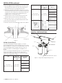
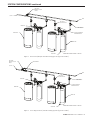
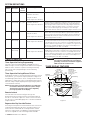
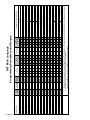
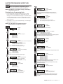
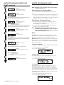
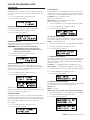
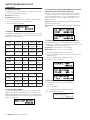
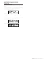
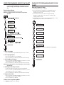
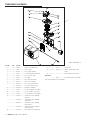
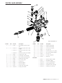
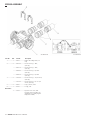
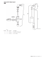
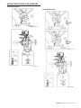
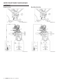
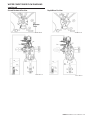
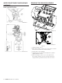
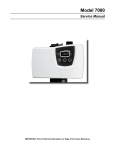
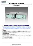
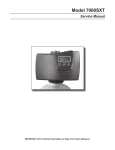
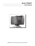
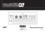
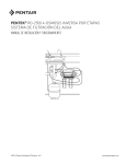
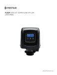
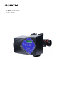
FLECK 7000 NXT
SERVICE MANUAL
TABLE OF CONTENTS
JOB SPECIFICATION SHEET..................................................... 3
INSTALLATION.......................................................................... 3
SYSTEM CONFIGURATIONS...................................................... 4
SYSTEM DEFINITIONS.............................................................. 6
TIMER OPERATION................................................................... 6
TIMER DISPLAY FEATURES...................................................... 6
TIMER DISPLAY - SCREEN EXAMPLES.................................... 7
NETWORK/COMMUNICATION CABLES
AND CONNECTIONS................................................................. 7
NXT MULTI LANGUAGE PROGRAMMING PARAMETERS
AND RANGES............................................................................ 8
MASTER PROGRAMMING MODE FLOW CHART....................... 9
MASTER PROGRAMMING GUIDE............................................. 10
USER PROGRAMMING MODE FLOW CHART............................ 14
DIAGNOSTIC PROGRAMMING MODE FLOW CHART................ 14
DIAGNOSTIC PROGRAMMING GUIDE....................................... 15
POWERHEAD ASSEMBLY......................................................... 16
CONTROL VALVE ASSEMBLY.................................................... 17
BYPASS ASSEMBLY.................................................................. 18
2310 SAFETY BRINE VALVE...................................................... 19
TROUBLESHOOTING................................................................. 20
GENERAL SERVICE HINTS FOR METER CONTROL................. 21
WATER CONDITIONER FLOW DIAGRAMS................................ 23
REMOVING THE GEAR BOX ASSEMBLY.................................... 26
INSERTING THE CIRCUIT BOARD............................................ 27
CONNECTING THE CIRCUIT BOARD........................................ 27
DIMENSIONAL DRAWINGS....................................................... 28
METER FLOW DATA................................................................... 29
INJECTOR FLOW DATA.............................................................. 30
SERVICE ASSEMBLIES............................................................. 31
2 • FLECK 7000 NXT Service Manual
IMPORTANT PLEASE READ:
• The information, specifications and illustrations
in this manual are based on the latest information
available at the time of printing. The manufacturer
reserves the right to make changes at any time
without notice.
• This manual is intended as a guide for service
of the valve only. System installation requires
information from a number of suppliers not known
at the time of manufacture. This product should be
installed by a plumbing professional.
• This unit is designed to be installed on potable
water system only.
• This product must be installed in compliance with
all state and municipal plumbing and electrical
codes. Permits may be required at the time of
installation.
• It is established that when daytime water pressure
exceeds 80 psi (5.5 bar), the maximum pressure
rating of 125 psi (8.6 bar) can be exceeded. A
pressure regulator must be installed on this
system or warranty is voided.
• Do not install the unit where temperatures may
drop below 32°F (0°C) or above 125°F (52°C).
• Do not place the unit in direct sunlight. Black
units will absorb radiant heat increasing internal
temperatures.
• Do not strike the valve or any of the components.
• Warranty of this product extends to manufacturing
defects. Misapplication of this product may result
in failure to properly condition water, or damage to
product.
• A prefilter should be used on installations in which
free solids are present.
• In some applications local municipalities treat
water with Chloramines. High Chloramine levels
may damage valve components.
• Correct and constant voltage must be supplied to
the controller to maintain proper function.
JOB SPECIFICATION SHEET
NOTE: Some options may not be available depending on valve
model or other options chosen.
Circle and/or fill in the appropriate data for future reference
1. System Type:
A. Meter Immediate
B. Time Clock Delayed
C. Volume Override Delayed
D. Volume Override Immediate
E. Meter Delayed Weekly Reserve
F. Meter Delayed Variable Reserve
G. Meter Delayed Fixed Reserve
2. Valve Type: 7000NXT
3. Regenerant Flow:
H. Downflow
I. Filter
J. Downflow Fill First
4. Display Format:
K. U.S.
L. Metric
5. Unit Capacity_______ Grains/Grams
6. Water Hardness_____ Grains/Grams
7. Capacity Safety Factor: Zero or __________________________ %
8. Volume Override:____________________________ Gallons or M3
9. Regeneration Day Override: Off or Every__________________ Days
10. Regeneration Time: Immediate or Delayed_____________ AM/PM
M. Regeneration Cycle Step #1: _ _ : _ _ : _ _
N. Regeneration Cycle Step #2: _ _ : _ _ : _ _
O. Regeneration Cycle Step #2: _ _ : _ _ : _ _
P. Regeneration Cycle Step #2: _ _ : _ _ : _ _
Q. Regeneration Cycle Step #2: _ _ : _ _ : _ _
R. Regeneration Cycle Step #2: _ _ : _ _ : _ _
11. Auxiliary Relay: Enabled or Disabled
S. Auxiliary Relay Start #1: _ : _ _ : _ _
T. Auxiliary Relay End #1: _ : _ _ : _ _
12. Chemical Pump: Enabled or Disabled
13. CPO Aux Relay Volume:______________________ Gallons or M3
14. CPO Aux Relay: _ _ : _ _ : _ _
15. Flow Meter Size: 1.25" Turbine
16. Generic Flow Meter:
Maximum Flow Rate: Add _ _ Gallons every _ _ Pulses
INSTALLATION
Water Pressure
A minimum of 20 psi (1.4 bar) of water pressure is required for
regeneration valve to operate effectively.
Electrical Facilities
An uninterrupted alternating current (A/C) supply is required.
Make certain voltage supply is compatible with unit before
installation and current supply is always on and cannot be
turned off with another switch.
Existing Plumbing
Condition of existing plumbing should be free from lime and
iron buildup. Replace piping that has heavy lime and/or iron
build-up. If piping is clogged with iron, install a separate iron
filter unit ahead of the water softener.
Location Of Softener And Drain
Locate the softener close to a clean working drain and connect
according to local plumbing codes.
BYPASS VALVES
Always provide for the installation of a bypass valve if unit is not
equipped with one.
CAUTION Minimum water pressure is 20 psi (1.3 bar).
Water pressure is not to exceed 125 psi (8.6 bar).
Minimum water temperature is 34°F (1.1°C).
Water temperature is not to exceed 110°F (43°C).
Ambient temperature 34°F to 122°F (1.1 to 50°C).
Disconnect all power sources before servicing.
Always operate with cover in place.
NOTE: This product should be installed by qualified
personnel. Comply with all plumbing codes when
installing this product. Comply with all electrical
codes when installing this product.
WARNING: This system must be depressurized before
removing any connections for servicing.
Installation Instructions
1. Place the softener tank where you want to install the unit.
Be sure the tank is level and on a firm, clean base.
2. Perform all plumbing according to local plumbing codes.
3. Refer to Figure 1. Cut the 1.05” (2.6 cm) distributor tube
flush with the top of the tank (A). Deburr the outside of the
tube (B) after cutting. Lubricate the O-ring (C) with nonpetroleum based grease.
4. Lubricate the distributor O-ring seal and tank O-ring seal.
Use only non-aerosol silicone lubricant.
5. Load media and place the control valve on the tank.
6. All soldering MUST be done on any connections requiring
soldering prior to connecting the main control valve. The
main control valve will be damaged if it is connected before
soldering.
NOTE: Allow fittings to cool before connecting.
7. Apply plumber tape to all threaded fittings.
8. On units with a bypass, place in Bypass position. Turn on
the main water supply. Open a cold soft water tap nearby
and let water run a few minutes or until the plumbing is
free of foreign material (usually solder) resulting from the
installation. Close the water tap when water runs clean.
9. Make plumbing connections to valve.
10.Plug the valve into an approved power source. Make all
FLECK 7000 NXT Service Manual • 3
INSTALLATION continued
electrical connections according to codes.
Valve
11.Place the bypass In Service position. Cycle the valve to the
Backwash position, and let the water flow slowly into the
mineral tank until the air is purged from the unit.
12.Add water to the brine tank until the top of the air check is
covered. Manually step the valve to the Brine Draw Position,
and allow the valve to draw water from the brine tank until
it stops. The air check will check at approximately the
midpoint of the screened intake area.
13.Manually step the valve to the Brine Refill Position, and
allow the valve to return to In Service automatically.
Hardware Kit
(Includes 2 each
nuts, O-ring, split
ring)
Grooved Adapter
Kit (Includes 2
adapters)
PN: 1070232 - 1.5"
Male Socket Weld Kit
PN: 1071180
PN: 1070246
Model: K524-X200-1402F
Model: K524109
PN: 1070233 1.5" Male NPT Kit
PN: 1070234 1.25" Female NPT
PN: 1071162 40 mm Male Socket
Weld Kit
14.With the valve In Service, check that there is at least 1”
(2.5 cm) of water above the grid (if used) in the brine tank.
15.Fill the brine tank with salt.
16.Allow the control to run automatically. Setup is now complete.
SYSTEM CONFIGURATIONS
BALL VALVE
MANUAL SHUTOFF
BYPASS
OUTLET
INLET
41119 Rev A
BALL VALVE
OUTLET SHUTOFF
Figure 1
Multiple System Shutoff
For systems requiring no hard water bypass, a solenoid
operated diaphragm valve can be installed in the service outlet
pipe (see Figures 2, 3, and 4). The solenoid would be connected
to the 24 VAC Bypass Relay terminal strip on the lower left
portion of the NXT circuit board (Figure 6 7000NXT Circuit
Board).
Plastic solenoid operated diaphragm valves are sold separately
from the pipe adapter kits. For each valve ordered, one
hardware kit, and one pipe adapter kit is required. Available
plastic valve configurations include:
Valve
Hardware Kit
(Includes 2 each
nuts, O-ring, split
ring)
Grooved Adapter
Kit (Includes 2
adapters)
PN:1070226 - 1"
Male Socket Weld Kit
PN: 1071106
PN: 1070244
Model: K521-X200-1402F
Model: K521109
PN: 1070227 1" Male NPT Kit
PN: 1070228 3/4" Female NPT Kit
PN: 1071091 22 mm Male Socket
Weld Kit
4 • FLECK 7000 NXT Service Manual
BALL VALVE
INLET SHUTOFF
BRINE LINE
SOLENOID OPERATED
DIAPHRAGM VALVE
BRINE TANK
DRAIN LINE
RESIN TANK
BR61689-7000-SYS4-1 Rev A
Figure 2 Single Tank Configuration (System 4)
SYSTEM CONFIGURATIONS continued
BALL VALVE
MANUAL SHUTOFF
BYPASS
OUTLET
INLET
BALL VALVE
OUTLET SHUTOFF
BRINE LINE
BALL VALVE
INLET SHUTOFF
BRINE TANK
SOLENOID OPERATED
DIAPHRAGM VALVE
DRAIN LINE
RESIN TANK
BR61689-7000-SYS59-2 Rev A
Figure 3 Interlocked / Multiple Tank Alternating Systems (Systems 5 and 9)
BALL VALVE
MANUAL SHUTOFF
BYPASS
REMOTE METER
OUTLET
INLET
BALL VALVE
OUTLET SHUTOFF
BRINE LINE
BALL VALVE
INLET SHUTOFF
SOLENOID OPERATED
DIAPHRAGM VALVE
BRINE TANK
DRAIN LINE
RESIN TANK
BR61689-7000-SYS67-2 Rev A
Figure 4 Series Regeneration / Twin Alternating Systems (Systems 6 and 7)
FLECK 7000 NXT Service Manual • 5
SYSTEM DEFINITIONS
System
Number
System
Description
# of
Tanks/
Controls
4
Single Unit
1
Type
Time Clock: No Meter
Operation Discussion
Single tank configuration.
Immediate: One Meter
Delayed: One Meter
Remote Signal Start: No Meter
5
Interlocked
2, 3, or 4
Immediate: All Meters
Remote Signal Start: No Meter
6
Series
Regeneration
2, 3, or 4
Immediate: One Meter
Delayed: One Meter
Remote Signal Start: No Meter
7
9
Twin
Alternating
2
Multiple Tank
Alternating
2, 3, or 4
Immediate: One Meter
Remote Signal Start: No Meter
Immediate: All Meters
Remote Signal Start: No Meter
TIMER OPERATION
All tanks in parallel supplying treated water. Each unit in the system
will have its own flow meter/sensor input. The control will delay the
start of Regeneration if another unit is already in Regeneration. Once
that unit has completed a Regeneration cycle, and has returned to
Service,the unit with longest regeneration queue time will begin
Regeneration. No more than one unit will be in Regeneration at a time.
All tanks in parallel supplying treated water. Only #1 control will
monitor flow meter/sensor input. When a regeneration is required
for the system, it will regenerate valve address #1 first, immediately
followed by #2, then #3, then #4 if installed. No more than one unit
will be in Regeneration at a time.
One tank online supplying treated water, one tank in Standby. Only
#1 control will monitor its flow meter/sensor input. Regeneration of
a unit will begin after the other control has left Standby and returned
to Service. When the Regeneration cycle is complete, the regenerated
unit will enter Standby. Standby on each tank is controlled by the 24
VAC solenoid bypass on the NXT circuit board.
One, two, or three tanks online supplying treated water, one tank in
Standby. Meter/sensor input is required on each tank. Regeneration of
a unit will begin after the other control has left Standby and returned
to Service. When the Regeneration cycle is complete, the regenerated
unit will enter Standby. Standby on each tank is controlled by the 24
VAC solenoid bypass on the NXT circuit board.
WARNING: Transformer must be grounded and ground
wire must be terminated to the circuit board
grounding screw before installation. Supplied
40VA transformer must be used.
Timer Operation During Programming
The timer enters the Program Mode in Standby or Service
Mode as long as it is not in regeneration. While in the Program
Mode the timer continues to operate normally monitoring
water usage. Timer programming is stored in memory
permanently.
TIMER DISPLAY FEATURES
Valve State
(INI, RGQ, SRV, LCK)
Valve
Address
System
Number
Timer Operation During A Power Failure
All program settings are stored in permanent memory. Current
valve position, cycle step time elapsed, and time of day are all
stored during a power failure. These settings will be restored
upon power re-application. Time is kept during a power failure,
and time of day is adjusted upon power up (as long as power is
restored within 12 hours).
NOTE: The time of day on the main display screen will flash
for 5 minutes when there has been a power outage.
The flashing of the time of day can be stopped by
pressing any button on the display.
Flow
Indicator
Time
of Day
Shift Button
Adjusts Values to the Left
Volume Remaining
Down Button
Adjusts Values Down
Up Button
Adjusts Values Up
Diagnostic Button
View Flow Rate, Peak Flow
Rate, Totalizer, Hours
Between Last Two
Regenerations, Hours Since
Last Regeneration, Adjustable
Volume Remaining, Valve
Position, Send & Receive
Errors, Software Version
Remote Lockout
The timer does not allow the unit/system to go into
Regeneration until the Regeneration Lockout Input signal to
the unit is cleared. This requires a contact closure to activate
the unit. The recommended gauge wire is 20 with a maximum
length of 500 feet.
Regeneration Day Override Feature
If the Day Override option is turned on and the valve reaches the
set Regeneration Day Override value, the Regeneration Cycle
starts if no other networked unit is in Regeneration. If other
units are in regeneration, it is added to a regeneration queue.
This occurs regardless of the remaining volume available.
6 • FLECK 7000 NXT Service Manual
Display Screen
Time of Day alternates
with Error Screen
Example: Valve #, Volume
Remaining, Errors
Extra Cycle Button
Cycle Valve in
Regeneration/Cycle
Programming Steps
Status LED
Figure 5
TIMER DISPLAY FEATURES continued
Valve State
5. In Service: System 6 Flow Meter Initiated (Lead Unit)
INI (Initializing) - INI will display on the screen for 30 to
45 seconds when initializing after a power failure reset or
programming.
RGQ (Regeneration Queued) - RGQ indicates that the reserve
has been entered in a delayed system and regeneration has
been queued. When in the main screen, press the Extra Cycle
button to toggle service (SRV) with RGQ.
SRV (Service) - SRV will display when the unit is In Service.
LCK (Lock) - Lock will be displayed when the terminal/remote
input block P4 on the circuit board is switched to "lock". See
the “Network/Communication Cables & Connections” section
of this manual.
LED Status Lights
Blue LED - Illuminates while the unit is In Service and no
errors exist. The unit will always be In Service unless a
regeneration trigger has occurred (green LED light will be
displayed). A blinking blue light indicates the timer is In
Service, and queued for regeneration.
NETWORK/COMMUNICATION CABLES
AND CONNECTIONS
Use a CAT5 Network/Communication cable.
Connect the network/communication cable first before
programming.
The maximum cable length between timers is 100 feet.
Connect each unit together from one communication port to
the next communication port. It does not matter which one
goes to the next one.
OPTIONAL MOTOR/PUMP ON DURING REGENERATION
(N.O. OUTPUT)
NEUTRAL
SWITCHED HOT
Ground
M1
24VAC/3A MAX.
30VDC/3A MAX.
UNSWITCHED HOT
Green LED - Illuminates when the unit is in Regeneration
mode, unless an error condition exists. A blinking green light
indicates the timer is in Standby, and not in Regeneration.
Red LED- Illuminates when there is an error.
Flow Indicator
Transformer
61920-0X
Motor
40968
A rotating line (appearing as a rotating star shape) will display
on the screen when flow is going through the meter.
TIMER DISPLAY - SCREEN EXAMPLES
1. In Service: System 4 Time Clock
METER
19791
RED
GREEN
BLACK
SWITCHED HOT
BYPASS RELAY
(SOLENOID) 24VAC
LOCK
S1
NEUTRAL
START
GROUND
4#
SRV
03:45PM
OPTIONAL REMOTE
SIGNAL START
SWITCH (N.O.)
REGEN IN 07 DAYS
2. In Service: System 4 Flow Meter Initiated or System 4 Flow
Meter Delayed
3. In Service: System 5 Flow Meter Initiated (Lead Unit)
1
4. In Service: System 5 Flow Meter Initiated (Lag Unit #3)
5#3 SRV
VOLUME
03:45PM
1000 g
2
43343 Rev A
Figure 6 7000NXT Circuit Board
The number of network/communication cables needed for
setup is one less than the total number of valves.
Two-Unit System: One network/communication cable
Three-Unit System: Two network/communication cables
Four-Unit Systems: Three network/communication cables
FLECK 7000 NXT Service Manual • 7
8 • FLECK 7000 NXT Service Manual
Notes
Add
Gallons or m 3
Every _ _ _ Pulses
Valve Address
Select Language
System Size
Regen Type
Regenerant Flow
Remote Signal Start
Display Format
Unit Capacity
Capacity Safety Factor
Feed Water Hardness
Regeneration Day Override
Regeneration Time
Cycle 1
Cycle 2
Cycle 3
Cycle 4
Cycle 5
Cycle 6
Auxiliary Relay
Aux Relay Output Start
Aux Relay Output End
Chemical Pump
CPO Aux Relay Volume
CPO Aux Relay Time
Flow Meter
Generic
Maximum Flow Rate
System Type
x
x
x
x
x
x
x
x
x
c
c
x
x
x
x
x
ouca-
4
Time
Clock
4
Metered
Delayed
5
Interlock
6
Series
7
Alternating
9
Alternating
Programming Parameter Ranges
x
x
1 thru 4
1
2
3
4
1
2
3
4
1
2
1
2
3
4
English, Espanol
x
x
x
x
x
x
x
x
x
x
x
x
x
x
1 thru 4
x
x
x
x
Time Clock, Metered Delayed, Metered Immediate
x
x
x
x
x
x
x
x
x
x
x
x
x
x
x
x
Downflow, Upflow, Upflow Fill First
x
x
x
x
x
x
x
x
x
x
x
x
x
x
x
x
Off, 00:01:00 - 04:00:00
x
x
x
x
x
x
x
x
x
x
x
x
x
x
x
x
x
x
x
x
x
x
x
x
x
x
x
x
US - Gallons
Metric - Liters
x
x
x
x
x
x
x
x
x
x
x
x
x
9000 - 9900000 Grains
90.0 - 199000.0 Grams
0- 50%
x
x
x
x
x
x
x
x
x
x
x
x
x
x
x
x
x
x
x
x
x
x
x
x
x
x
1 - 199 Grains/Gallons
2 - 199 mg/l
Off, 1 - 99
x
x
x
x
x
x
x
x
x
x
x
x
x
o
o
o
o
o
o
o
o
o
o
o
o
o
12:00 a.m. - 11:59 p.m.
00:00 - 23:59 Hour
00:00:00 - 04:00:00
x
x
x
x
x
x
x
x
x
x
x
x
x
x
x
x
Off, 00:00:00 - 04:00:00
x
x
x
x
x
x
x
x
x
x
x
x
x
x
x
x
Off, 00:00:00 - 04:00:00
x
x
x
x
x
x
x
x
x
x
x
x
x
x
x
x
Off, 00:00:00 - 04:00:00
x
x
x
x
x
x
x
x
x
x
x
x
x
x
x
x
Off, 00:00:00 - 04:00:00
x
x
x
x
x
x
x
x
x
x
x
x
x
x
x
x
Off, 00:00:00 - 04:00:00
x
x
x
x
x
x
x
x
x
x
x
x
x
x
x
x
Enabled, Disabled
x
x
x
x
x
x
u
x
x
x
u
x
x
x
x
x
00:00:00 to Total Regeneration Time - 1
c
c
c
c
c
c
c
c
c
c
c
c
c
c
c
c
Start Time + 1 to Total Regeneration Time
c
c
c
c
c
c
c
c
c
c
c
c
c
c
c
c
Enabled, Disabled
x
x
x
x
x
x
u
u
x
x
x
x
c
c
c
c
c
c
c
c
c
c
c
c
1 - 999 gallons
00.1 - 99.9 liters
c
c
c
c
c
c
c
c
c
c
c
c
00:00:01 - 02:00:00
00:00:01 - 02:00:00
1.2t (7000), Generic
x
x
x
x
x
x
x
x
x
x
x
x
x
x
x
x
x
x
x
x
x
x
x
x
20 - 2000 GPM
a
a
a
a
a
a
a
a
a
a
a
a
2.0 - 200.0 m 3m
a
a
a
a
a
a
a
a
a
a
a
a
1 - 255 Gallons
1.0 - 25.5 m 3
a
a
a
a
a
a
a
a
a
a
a
a
1 - 255
1 - 255
Regeneration Time will only be viewed if Regeneration Day Override is used.
If Auxiliary Relay is Enabled then Chemical Pump Relay will not be viewed or if Chemical Pump Relay is Enabled then Auxiliary Relay will not be viewed.
All Relay Output parameters programming will be viewed if Enabled
If Generic Flow Meter is chosen, then programming parameters will be viewed.
4
Metered
Immediate
NXT Multi Language
Programming Parameters and Ranges
Filter
Iron Filter (Do Not Use)
MASTER PROGRAMMING MODE FLOW
CHART
CAUTION Before entering Master Programming, please
contact your local professional water dealer.
NOTE: Depending on current option settings, some displays
cannot be viewed or set.
Entering Master Programming Mode
1. Press and hold the Shift and Up buttons for 5 seconds.
Press the Extra Cycle button once per display until all
displays are viewed and Normal Display is resumed. Option
setting displays may be changed as required by pressing
either Up or Down button. Use the Shift button to move one
space to the left.
2. Depending on current valve programming, certain displays
may not be viewed or set.
NOTE: If the "D" button is pressed while in master
programming, no changes will be saved.
Example:
English
Example:
00:06:00 (Default)
(Hours:Minutes:Seconds)
Options: 00:06:00 (Default)
Range: 1 second to 99 minutes (1 hour, 39 minutes)
Example:
U.S. Gallons (Default)
Options: U.S. - Gallons (Default)
European Units - Liters (Metric)
NOTE: In U.S. - Gallons mode, the display will be in 12-hour time.
NOTE: In European Units - Liters (Metric) mode, the display will be in
24-hour time.
Example:
Grains (Default)
Options: Grains (in U.S. Format) (Default)
Grams (in Metric Format)
Range: 9,000 to 9,900,000 Grain Capacity in U.S. Format
90.0 to 190,000 grams CaCO3 Capacity in Metric Format
Example:
00% (Default)
Range: 0 to 50%
NOTE: Use the Shift button to move to the left.
Options: English
Spanish
Example:
15 GPG (U.S. Format) (Default)
Example:
System Type 4, Single Unit
Options: System 4 (single unit)
System 5 (2-4 units)
System 6 (2-4 units)
System 7 (2 units)
System 9 (2-4 units)
Range: 1 to 199 Grains/Gallon (U.S. Format)
2 to 199 miligrams CaCOs/L (Metric Format)
NOTE: Use the Shift button to move to the left.
NOTE: This screen will only display on the lead unit for System Types 6 & 7.
For all other System Types, it will display for all units.
Example:
Off (Default)
Example:
Valve Address #2 (Second Control Valve) (Default)
Options: Valve Address #1 (First Control Valve)
Valve Address #2 (Second Control Valve) (Default)
Valve Address #3 (Third Control Valve)
Valve Address #4 (Fourth Control Valve)
Example:
1 Day
Options: Off (Default) or On
Range: 1 to 99 Days
NOTE: This screen will not display for System Type 4.
Example:
2 Valves in the System (Default)
Options: 2 Valves in the System (Default)
3 Valves in the System
4 Valves in the System
Range: 2 to 4 Valves in the System
Example:
2:00 A.M. (Default)
Options: A.M. (U.S. Format)
HR (Metric Format)
NOTE: Regeneration time will not appear unless Regeneration Day Override
is on.
Example:
Cycle 1 in Back Wash Mode
NOTE: This screen will not display for System Type 4.
Example:
Time Clock Delayed (Default)
Options: Time Clock Delayed (System 4 Only) (Default)
Meter Immediate (All System Types)
Meter Delayed Fixed Reserve (Systems 4 & 6 Only)
Example:
Downflow (Default)
Options: Downflow (Default)
Downflow Fill First
Filter
Iron Filter (Do Not Use)
Options: Regeneration Cycle Step #1
Regeneration Cycle Step #2
Regeneration Cycle Step #3
Regeneration Cycle Step #4
Regeneration Cycle Step #5
Regeneration Cycle Step #6
NOTE: Please refer to the “Regenerant Flow Default Cycle Steps & Times”
in the Master Programming Mode section of the manual.
NOTE: If Stager is chosen for Valve Type, the Regeneration Cycle Step
description will not display.
Example:
Auxiliary Relay is Disabled
Options: Enabled
Disabled (Default)
Example:
00:06:00 (Default)
(Hours:Minutes:Seconds)
Options: 00:06:00 (Default)
Range: 1 second to 99 minutes (1 hour, 39 minutes)
Example:
U.S. Gallons (Default)
Example:
Auxiliary Relay Output in Start 1 at
0 hours, 0 minutes, & 0 seconds
Range:
Options: U.S. - Gallons (Default)
European Units - Liters (Metric)
NOTE: In U.S. - Gallons mode, the display will be in 12-hour time.
NOTE: In European Units - Liters (Metric) mode, the display will be in
24-hour time.
Example:
Grains (Default)
00:00:00 to 18:00:00
NOTE: Only displayed if Auxiliary Relay is enabled in previous screen.
Auxiliary Relay will only display if Chemical Pump is OFF for System
Types 6 & 7.
Example:
Auxiliary Relay Output in End 1 at
0 hours, 0 minutes, & 0 seconds
Range:
00:00:00 to 18:00:00
FLECK
7000 NXT Service Manual • 9
Example:
Example:
Auxiliary Relay Output in Start 1 at
0 hours, 0 minutes, & 0 seconds
MASTER
PROGRAMMING MODE FLOW
Range: 00:00:00 to 18:00:00
NOTE: Only displayed if Auxiliary Relay is enabled in previous screen.
CHARTAuxiliary
continued
Relay will only display if Chemical Pump is OFF for System
Types 6 & 7.
Example:
Auxiliary Relay Output in End 1 at
0 hours, 0 minutes, & 0 seconds
Range:
00:00:00 to 18:00:00
Example:
Chemical Pump is Disabled
Options: Enabled
Disabled (Default)
NOTE: This screen will only display on the lead unit for System Types 6 & 7.
For all other System Types, it will display for all units.
Example:
Chemical Pump Auxiliary Relay
Volume at 0 Gallons
Range: 000 to 999 gallons in U.S. Format
0.000 to 9.999 L in Metric Format
NOTE: Only displayed on units that physically have a meter (Lead always has
a meter). Only shown if Auxiliary Relay is disabled on System Types 6 & 7.
Example:
Chemical Pump Auxiliary Relay at 0 Hours,
0 Minutes, & 0 Seconds
Range:
00:00:00 to 02:00:00
Example:
1.2 Turbine Flow Meter
Options: 1.2 Turbine
Generic
NOTES: Default flow meter type is based on the valve type. This screen will
only display on the lead unit for System Types 6 & 7. All other system types
it will display for all units.
Example:
Maximum Flow Rate of 0 gpm
Range:
20 - 2,000 gpm (U.S. Format)
2.0 - 200.0 L (Metric Format)
NOTE: Only displayed if “Generic” is chosen for the flow meter.
Example:
Add 1 Gallon for Each Pulse in U.S. Format
MASTER PROGRAMMING GUIDE
When the Master Programming Mode is entered, parameters
can be set to make the timer(s) function as needed.
NOTE: Depending on current option settings, some displays
cannot be viewed or set.
Entering Master Programming Mode:
1. Press and hold the Shift and Up buttons for 5 seconds.
OR
2. Set the time of day display to 12:01 PM or 12:01HR (See the
“Setting the Time of Day” section on the “Timer Operation”
page). Then go to the main display screen, press the Up and
Down buttons at the same time for 5 seconds.
Exiting Master Programming Mode
1. Press the Extra Cycle button once per display until all
are viewed. Master Programming Mode is exited and the
normal display screen appears.
2. To exit the Master Programming Mode without saving
changes, press the Diagnostic button.
NOTE: If no keypad activity is made for 5 minutes while in
the Master Programming Mode, or if there is a power
failure, no changes will be saved, and the unit will go
back to the main display screen.
Resets
Soft Reset: Press and hold the Up and Down buttons for 25
seconds until 12:00PM (or 12:00HR) appears. This resets all
parameters except for the flow meter totalizer volume.
Master Reset: Hold the Extra Cycle button while powering up
the unit. This resets all of the parameters in the unit. Check
and verify the choices selected in Master Programming Mode
prior to this procedure.
1. Choice of Language
This option selects the language for programming and display.
1. Use Up or Down to select language.
2. Press the Extra Cycle button.
Options: Gallons (U.S. Format)
Liters (Metric Format)
Range:
1 - 99 Gallons (U.S. Format)
0.1 - 09.9 L (Metric Format)
Pulses: 1 - 99
NOTE: Only displayed if “Generic” is chosen for the flow meter.
2. System Type
This program type selects the system type (4, 5, 6, 7, or 9).
1. Use Up or Down buttons to adjust this value.
Example:
Master Programming Mode is Exiting
2. Press the Extra Cycle button.
3. Valve Address
This program step selects the valve address (1, 2, 3, or 4)
within the network. The address is needed for each timer
for communication. The #1 is the “master” or “lead” which
contains programmed parameters, that will be used by all of
the timer(s) in the network to control Regeneration, in Service,
or Standby of all the valve(s) in the system. This option will be
skipped if System 4 is selected.
1. Use Up or Down buttons to adjust this value.
2. Press the Extra Cycle button.
10 • FLECK 7000 NXT Service Manual
MASTER PROGRAMMING GUIDE
continued
4. System Size
9. Unit Capacity
This program step is used to set up the number of valves (2, 3,
or 4) in the system. This option will be skipped if System 4 is
selected.
This program selects the individual timer’s total capacity of
hardness that can be removed. The unit capacity is measured
in grains if in U.S. mode and grams CaCO3 in Metric mode.
U.S. Range: 9,000 to 9,900,000 Grains
(Default = 300,000 Grains)
Metric Range: 90.0 to 199,000.0 grams CaCO3
(Default = 300.0 grams CaCO3)
1. Use Up or Down buttons to adjust this value.
2. Press the Extra Cycle button.
1. Use the Shift button to select the digit you want to modify.
5. Regeneration Type
This program step is used to set up the trigger type.
2. Use Up or Down buttons to adjust this value.
3. Press the Extra Cycle button.
1. Use Up or Down buttons to adjust this value.
2. Press the Extra Cycle button.
10. Capacity Safety Factor
6. Regenerant Flow
This program step selects the regenerant flow type (Downflow,
Downflow Fill First, Filter, or Iron Filter).
CAUTION Do not select the Iron Filter option when
programming this control. This selection is
incompatible with the valve and may cause the
valve to operate incorrectly.
This program step is used to adjust the capacity of the system.
This is a percentage by which the unit’s capacity is reduced.
Range: 0 – 50% (Default = 0%)
1. Use the Shift button to select the digit you want to modify.
2. Use Up or Down buttons to adjust this value.
3. Press the Extra Cycle button.
1. Use Up or Down buttons to adjust this value.
2. Press the Extra Cycle button.
7. Remote Signal Start
This program step selects the remote signal start. Hours,
minutes, and seconds can be changed. When Remote Signal
Start is active, the main screen will display. The options are
either Off or set to the desired time.
1. Use Up or Down buttons to adjust this value.
2. Press the Extra Cycle button.
11. Feed Water (Hardness)
This program step is used to set the feed water hardness. The
system will automatically calculate volume remaining based
on the Unit Capacity, Capacity Safety Factor and Feed Water
Hardness entered.
U.S. Range: 1 – 199 gpg (Grains per Gallon)(Default = 15)
Metric Range: 2 – 199 milligrams CaCO3/Liter (Default = 30)
1. Use the Shift button to select the digit you want to modify.
2. Use Up or Down buttons to adjust this value.
3. Press the Extra Cycle button.
12. Regeneration Day Override
Example of setting Remote Signal Start to 6 minutes. The
display counts down to 0. If Remote Signal Start is detected for
6 minutes, it will remotely signal start.
8. Display Format
This program step is used to set the desired volume display
format. This option must be the same on all system units. U.S.
will display volumes in gallons and is in 12 hour timekeeping.
Metric will display volumes in liters and is in 24 hour
timekeeping.
This program step sets the maximum amount of time (in days)
the unit can be In Service without a Regeneration.
Default: OFF
Range: 1 - 99 Days
NOTE: If “On,” the screen for regeneration time will display.
1. Use the Shift button to select the digit you want to modify.
2. Use Up or Down buttons to adjust this value.
3. Press the Extra Cycle button.
1. Use Up or Down buttons to adjust this value.
2. Press the Extra Cycle button.
FLECK 7000 NXT Service Manual • 11
MASTER PROGRAMMING GUIDE
continued
13. Regeneration Time
This program step sets time of day for a delayed regeneration
to occur, or regeneration day override.
Default U.S.: 02:00 AM
Default Metric: 02:00 HR
1. Use the Shift button to select the digit you want to modify.
2. Use Up or Down buttons to adjust this value.
3. Press the Extra Cycle button.
16. Timed Auxiliary Relay Output Window (Start & End
Time Setting, If Auxiliary Relay is Enabled)
This option setting consists of two displays. The first display
sets the turn-on time of the output, referenced to the start
of the first Regeneration Cycle. The second display sets the
output turn-off time, referenced again to the start of first
Regeneration Cycle.
Start Time: Anytime during Regeneration (Except Last Minute
of the Regeneration Time)
End Time: At start time, and anytime during the regeneration
cycle.
14. Regeneration Cycle Steps
This program step programs the Regeneration Cycle step times
1 through 5. Please refer to the chart below for regenerant flow
default cycle steps and times.
Regenerant
Flow
17. Chemical Pump Auxiliary Relay Output Window
Cycle 1
Time
Cycle 2
Time
Downflow
Backwash
10
Minutes
Brine Draw/
Slow Rinse
60
Minutes
DF Fill First
Brine Tank
Fill
10
Minutes
Brine
Making
60
Minutes
Filter
Backwash
10
Minutes
Rapid Rinse
10
Minutes
1. Activate Output After Volume Set is Reached.
Cycle 3
Time
Cycle 4
Time
3. Use Up or Down buttons to adjust this value.
Downflow
2nd
Backwash
10
Minutes
Rapid Rinse
12
Minutes
DF Fill First
Backwash
10
Minutes
Brine Draw/
Slow Rinse
10
Minutes
NA
NA
NA
NA
Cycle 5
Time
Cycle 6
Time
Downflow
Brine Fill
12
Minutes
NA
NA
DF Fill First
2nd
Backwash
5
Minutes
Rapid Rinse
10
Minutes
NA
NA
NA
NA
Regenerant
Flow
Filter
Regenerant
Flow
Filter
15. Auxiliary Relay Output
The next two displays are part of a series of settings used to
program the optional relay output. The first setting turns the
output On/Off during Regeneration only. The second turns the
output On during Service only, every time a set volume of water
used has accumulated.
12 • FLECK 7000 NXT Service Manual
This option setting consists of two displays. The first display
sets the volume of water flow at which the output turns On. The
second display sets the time of the output.
U.S. Range: 0 – 999 Gallons (1 – 999 Seconds)
Metric Range: 0.00 – 9.99 m3 (1 – 999 Seconds)
2. Use the Shift button to move one space to the left for each
number entered.
4. Press the Extra Cycle button.
18. Flow Meter Size (Default to Valve Type)
This program step sets the size of the flow meter.
1.2” Turbine
Generic Flow Meter
1. Use Up or Down buttons to adjust this value.
2. Press the Extra Cycle button.
FLOW METER:
1.2 TURBINE
MASTER PROGRAMMING GUIDE
continued
19. Maximum Flow Rate
This program step sets maximum flow rate of the generic flow
meter.
1. Press the Shift button to select the digit you want to modify.
2. Press the Up or Down buttons to adjust this value.
3. Press the Extra Cycle button.
20. Pulses per Gallon/Liter
This program step sets the pulses per gallon/liter for generic
flow meters.
1. Press the Shift button to select the digit you want to modify.
2. Press the Up or Down buttons to adjust this value.
3. Press the Extra Cycle button.
22. End of Master Programming Mode
FLECK 7000 NXT Service Manual • 13
USER PROGRAMMING MODE FLOW CHART
NOTE: User Mode is only displayed when a metered option
is chosen under System Type. Depending on current
option settings, some displays cannot be viewed or
set.
Entering User Mode
Hold the Up and Down buttons for 5 seconds.
NOTE: User Mode cannot be entered on the Lag unit for
System 6.
DIAGNOSTIC PROGRAMMING MODE FLOW
CHART
Entering Diagnostic Mode
1. Push and release the "D" button.
2. Press the Extra Cycle button once per display until all
displays are viewed and Normal Display is resumed.
Changes will be saved.
3. Push and release the"D" button at anytime during
diagnostic mode and the timer will exit the mode. No
changes will be saved.
4. Depending on the current controller programming, certain
displays may not be able to be viewed or set.
Options: English
Spanish
CURRENT FLOW
RATE:
0 gpm
PEAK FLOW RATE:
0 gpm
TOTALIZER:
130 g
LAST TWO REGENS:
0 HOURS
LAST REGEN
0 HOURS
VOLUME REMAINING
TANK:
0000000 g
NOTE: If a System 6, Unit #1 of “Tank Remaining” will display “System
Remaining”.
1. Enter User Mode
VALVE ADDRESS
#2
• Press and hold the Up and Down buttons for 5 seconds.
2. Set Language Option
• Press Up or Down to select language.
• Press the Extra Cycle button to proceed to the next step.
3. Set Feed Water Hardness
• Press the Shift, Up, and Down buttons to move the cursor
and change the value of the numbers.
• Press the Extra Cycle button to proceed to the next step.
NOTE: Only displayed when a metered option is chosen under
System Type.
4. Set Regeneration Day Override
• To turn On and set the days, press the Down button.
• Press the Shift, Up, and Down buttons to move the cursor
and change the value of the numbers.
• Press the Extra Cycle button to proceed to the next step.
5. Regeneration Time
• Press the Shift, Up, and Down buttons to move the cursor
and change the value of the numbers.
• Press the Extra Cycle button.
6.End of User Programming Mode
14 • FLECK 7000 NXT Service Manual
VERSION: NXT
1.00
DIAGNOSTIC PROGRAMMING GUIDE
When the Diagnostics Mode is entered, all available displays
are viewed as needed. Depending on current option settings,
some displays cannot be viewed.
Hours Since Last Regeneration
Overview Diagnostic Mode
1. Depress the Extra Cycle button.
The current diagnostic will be displayed until Extra Cycle key is
pressed. There is no time limit on each display. The timer will
display individual valve information, not system information.
In the event of regeneration occurring while displaying
diagnostics, the regeneration step and time remaining will be
displayed. When regeneration has been completed, the display
will return to the normal Time of Day display.
Entering and Exiting Diagnostic Mode
Push and Release the “D” button to enter. Pressing the Extra
Cycle button will move to the next diagnostic to be displayed.
Push the Extra Cycle button once per display until all are
viewed. Pressing the Diagnostic button, while in the Diagnostic
Mode, will cause the unit to leave the Diagnostic Mode and
return to the normal time of day display.
Current Flow Rate
Flow Rate for this particular Timer will be calculated and
displayed. Flow rates will be calculated every second. The
display updates once per second. Flow rates are dependent
upon the meter used.
• 1.2” Turbine Meter: 40 gpm
1. Press the Extra Cycle button.
The hours since the last regeneration will be saved and
displayed.
Volume Remaining (This Tank Only)
Volume remaining in the current tank will be adjustable when
displayed in this mode. Regeneration will occur if set to zero.
NOTE: Volume Remaining will not display for System
Type 6.
The maximum ranges are the same as the maximum volume
calculated on the main screen.
1. Press the Shift button to select the digit you want to modify.
2. Use Up or Down buttons to adjust this value.
3. Depress the Extra Cycle button
Volume Remaining (System)
Volume remaining in the system cannot be edited when
displayed in this mode, except for the Lead unit. It can only be
viewed on the Lag unit.
1. Depress the Extra Cycle button
Peak Flow Rate
The Peak Flow Rate since the last regeneration will be
captured.
Range: 0 to Maximum Number
1. Press the Extra Cycle button.
Totalizer
The total volume of treated water that passes through a meter
will be counted.
NOTE: The user cannot edit below the current volume
remaining.
1. Reset to zero by holding the Up and Down arrow keys for 5
seconds during the Totalizer display.
2. Press the Extra Cycle button.
Valve Address
This diagnostic display is for 2 control valves or more in a
system. Single valve systems (System 4) do not display this
option.
1. Depress the Extra Cycle button.
Software Version
The electronic timer’s software program version number will
be displayed.
1. Depress the Extra Cycle button to exit.
x.xx
NOTE: Diagnostic Mode programming will stop if the system
goes into regeneration.
Hours Between Last Two Regenerations
The hours between the last two regenerations will be saved
and displayed.
1. Depress the Extra Cycle button.
FLECK 7000 NXT Service Manual • 15
POWERHEAD ASSEMBLY
18
61501-7000XT Rev A
Item No.
QTY
Part No.
Description
1����������������1�������� 42349�����������������Motor, 24V, 2 RPM, 7000
16���������������1�������� 41122�����������������O-ring, -007
2����������������1�������� 10218�����������������Switch, Micro
17���������������1�������� 40960-03������������Label, UL Nameplate, 7000,
US/24
3����������������1�������� 40978�����������������Plate, Upper Support
4����������������1�������� 61729�����������������Circuit Board Assy, 7000 NXT
5����������������1�������� 40702�����������������Shaft, Encoder, 7000
6����������������1�������� 40703�����������������Gear, Main
7����������������1�������� 40704�����������������Cam, Brine, Downflow
8����������������1�������� 40979�����������������Plate, Lower Support
9����������������1�������� 61635-01������������Cover Assy, 7000-II, Black
1�������� 61634-01������������Cover Assy, 7000-II, Gray
10���������������1�������� 40980-20������������Backplate, 7000NXT
11���������������4�������� 13602�����������������Screw, Phil Rd Hd, 6-32 x 5/16
12���������������1�������� 12473�����������������Screw, Hex Wsh, 10-24 x 5/8
13���������������2�������� 11805�����������������Screw, Rd Hd, 4-40 x 5/8 Type 1
14���������������1�������� 61920-01������������Transformer Assy, 7000NXT,
40VA, US
��������������������������� 61920-02������������Transformer Assy, 7000NXT,
40VA, Japan
��������������������������� 61920-03������������Transformer Assy, 7000NXT,
40VA, Europe
��������������������������� 61920-04������������Transformer Assy, 7000NXT,
40VA, Australia
15���������������1�������� 19791-01������������Meter Cable Assy, Turbine/SE
16 • FLECK 7000 NXT Service Manual
18������������������������ *�������������������������7000 Complete Powerhead
Not Shown:
1�������� 61763�����������������Kit, CAN Communication Cable
*Call your distributor for Part Number
CONTROL VALVE ASSEMBLY
61500-7000EXP Rev C
Item No.
QTY
Part No.
Description
Item No.
QTY
Part No.
Description
1����������������1�������� 61050�����������������Valve Body Assy, 7000, 32 mm
Dist
13���������������1�������� 40946�����������������Clip, Brine Retaining
2����������������1�������� 61542-10������������Piston Assy, 7000, Softener, D/F
35 gpm
15���������������1�������� 40950�����������������Screen, Injector, 7000
�������� 61453-10������������Piston Assy, 7000, Softener, D/F
28 gpm
�������� 61452-20������������Piston Assy, 7000, Filter 35GPM
14���������������1�������� 40945�����������������Clip, Drain Retaining
16���������������1�������� 40951�����������������O-ring, -220
17���������������1�������� 18280�����������������Collector, Top, 1” x .011, Gray
18���������������1�������� 61419�����������������Kit, 1.05” Distributor, Adapter
3����������������3�������� 40576�����������������Clip, H, Plastic, 7000
19���������������1�������� 19054�����������������O-ring, -124
4����������������1�������� 61438�����������������Seal & Spacer Kit, 7000, D/F
20���������������1�������� 18303-01������������O-ring, -336, 560CD
5����������������1�������� 60016-01������������Brine Valve Assy, 7000, 560CD
23���������������1�������� 61XXX�����������������DLFC Kits
6����������������1�������� 40577�����������������Turbine Meter Assy, 7000
Not Shown:
7����������������1�������� 61XXX�����������������Injector Assy, 7000
�������� 40677�����������������Tube, Distributor, 32MM
8����������������1�������� 40556�����������������Cap, Injector
�������� 40924�����������������Distributor, 32MM
9����������������1�������� 61XXX�����������������BLFC Assemblies
�������� 40697-02������������Collector, 32MM Bayonet
10���������������1�������� 61XXX�����������������DLFC Assemblies
�������� 12763-10������������Stuffer Tool Assy, 7000
11���������������1�������� 43776�����������������O-ring, -021, 7000, CSTM
�������� 40947-01������������Plug, Brine Valve, w/O-ring
12���������������2�������� 13302-01������������O-ring, -014, 560CD
�������� 40990-01������������Plug, Injector, w/O-ring
FLECK 7000 NXT Service Manual • 17
BYPASS ASSEMBLY
41118 Rev A
Item No.
QTY
Part No.
Description
1����������������1�������� 40569�����������������Bypass Assembly, 7000, Less
Clip
2����������������2�������� 40563-01������������Connector Assy, 1” NPT,
w/O-ring
�������� 40563-11������������Connector Assy, 1” BSP,
w/O-ring
�������� 40565-01������������Connector Assy, 1 1/4” NPT
w/O-ring
�������� 40565-11������������Connector Assy, 1 1/4” BSP
w/O-ring
3����������������2�������� 41242-01������������Connector Assy, 1” & 1/4” Sweat,
w/O-ring
�������� 41243-01������������Connector Assy, 1 1/4” & 1 1/2”
Sweat, w/O-ring
4����������������2�������� 40576�����������������Clip, H, Plastic, 7000
5����������������1�������� 40951�����������������O-ring, -220
Not Shown:
1�������� 61462�����������������By-Pass Service Kit, 7000
(Includes all internal parts for
7000 bypass assembly - bypass
body not included)
18 • FLECK 7000 NXT Service Manual
41147 Rev A
2310 SAFETY BRINE VALVE
42112 Rev A
Item No.
QTY
Part No.
Description
1����������������1�������� 60014�����������������Safety Brine Valve Assy, 2310
2����������������1�������� 60068-30������������Float Assy, 2310, w/30” Rod
3����������������1�������� 60002-34������������Air Check, #500
FLECK 7000 NXT Service Manual • 19
TROUBLESHOOTING
Detected Errors
NOTE: It can take up to 30 seconds for an error to be detected
and displayed. All errors on each timer in the system
must be displayed before the errors can be corrected.
If a communication error is detected, an Error Screen will
alternate with the Main (time of day) Screen every few seconds.
• All units In Service remain in the In Service position.
• All units in Standby go to In Service.
• Any unit in Regeneration when the error occurs
completes Regeneration and goes to In Service.
• No units are allowed to start a Regeneration Cycle while
the error condition exists, unless they are manually forced
into Regeneration.
• When an error is corrected and the error no longer
displays (it may take several seconds for all of the units
in a system to stop displaying the error message), the
system returns to normal operation.
NOTE: During the error condition the control continues
to monitor the flow meter and update the volume
remaining. Once the error condition is corrected all
units return to the operating status they were in prior
to the error. Regeneration queue is rebuilt according
to the normal system operation. Or, if more than
one unit has been queued for regeneration, then the
queue is rebuilt according to which one communicates
first.
Cause For Error
Correction
One or more units have a
missing or bad communication
cable.
Connect the communication
cables and/or replace.
One or more units has a
communication cable plugged
into the wrong receptacle.
Connect the communication cable
as shown in the wiring diagrams.
One or more units is not
powered.
Power all units.
Programming Errors
During the error condition the control continues to monitor the
flow meter and update the remaining capacity. Once the error
condition is corrected all units return to the operating status
they were in prior to the error and regeneration is queued
according to the normal system operation. If reprogramming
the unit in the Master Programming Mode clears the error, the
volume remaining may be reset to the full unit capacity (i.e. as
though it were just regenerated).
• All units in Standby go In Service.
• Any unit in regeneration when the error occurs completes
regeneration and goes to In Service.
• No units are allowed to start a regeneration cycle while
the error condition exists.
When the problem is corrected and the error no longer displays
(it may take several seconds for all of the units in a system
to stop displaying the error message), the system returns to
normal operation.
Programming Errors Detected
• Duplicate unit addresses or numbers
• Size of system ex: if sized for a 4 units, and only have 2 units
• Display format mismatches
Solution
• Program the units correctly in the Master Programming
Mode.
20 • FLECK 7000 NXT Service Manual
NOTE: If these errors are detected, numbers 1 through 3
become true, and the main screen (time of day) will
alternate with an error screen.
Cause For Error
Correction
Any or all of two or more units
programmed with the same
unit number (Matching Address
Error)
Program the units correctly in
the Master Programming Mode
Flashing/blinking display
Power outage has occurred
Format Mismatch (Units have
both U.S. and Metric Formats)
Verify all units have same Format
selected (all U.S. or all Metric)
No messages displayed/small
black squares appear in display
Turn the contrast button on the
back of unit until text appears
Size Error (Units not correctly
numbered/more than one unit
has the same number assigned)
Check each unit and verify each
as the correct number, and that
each number is used once
Com Error (Communication
Error)
Check the wiring of the system
and verify it is correct and that
all are connected
TROUBLESHOOTING continued
GENERAL SERVICE HINTS FOR METER
CONTROL
Detected Error
Problem: Softener delivers hard water
Reason: Reserve capacity has been exceeded.
Correction: Check salt dosage requirements and review
programmed unit capacity, capacity safety factor, and feed
water hardness settings.
Reason: Meter is not measuring flow.
Correction: Check meter with meter checker.
Example Error Screens
DETECTED ERROR=
E2
RESET UNIT
1. Go through Master Programming to program the unit.
No Message #1
DETECTED ERROR=
NO MESSAGE #1
1. Make sure all communication cables are connected.
2. If "No Message #1" ensure it is the lead unit.
3. Ensure #1 is configured for the correct system type.
No Message #3
DETECTED ERROR=
NO MESSAGE #3
1. Make sure all communication cables are connected.
2. If "No Message #3" ensure it is unit #3.
3. Ensure #3 is configured for the correct system type.
Program Mismatch
DETECTED ERROR=
PROGRAM MISMATCH
1. Ensure the units on the network are not configured the
same as #1/the Lead unit.
Exceed Unit Size
DETECTED ERROR=
EXCEED UNIT SIZE
1. There are more units on the system than the Lead is
programmed for.
Matching Address
DETECTED ERROR=
MATCHING ADDRESS
1. The unit is programmed the same # as another unit.
NOTE: The rest of the system will still function without this
unit.
FLECK 7000 NXT Service Manual • 21
TROUBLESHOOTING continued
Problem
Cause
Correction
Water conditioner fails to
regenerate.
Electrical service to unit has been
interrupted
Assure permanent electrical service (check fuse,
plug, pull chain, or switch).
Timer is defective.
Replace timer.
Power failure.
Reset time of day.
By-pass valve is open.
Close by-pass valve.
No salt is in brine tank.
Add salt to brine tank and maintain salt level above
water level.
Injector screen plugged.
Clean injector screen.
Insufficient water flowing into brine tank.
Check brine tank fill time and clean brine line flow
control if plugged.
Hot water tank hardness.
Repeated flushings of the hot water tank is
required.
Leak at distributor tube.
Make sure distributor tube is not cracked. Check
O-ring and tube pilot.
Internal valve leak.
Replace seals and spacers and/or piston.
Improper salt setting.
Check salt usage and salt setting.
Excessive water in brine tank.
See "Excessive water in brine tank".
Iron buildup in line to water conditioner.
Clean line to water conditioner.
Iron buildup in water conditioner.
Clean control and add mineral cleaner to mineral
bed. Increase frequency of regeneration.
Inlet of control plugged due to foreign
material broken loose from pipes by recent
work done on plumbing system.
Remove piston and clean control.
Air in water system.
Assure that well system has proper air eliminator
control. Check for dry well condition.
Improperly sized drain line flow control.
Check for proper drain rate.
Iron in conditioned water.
Fouled mineral bed.
Check backwash, brine draw, and brine tank fill.
Increase frequency of regeneration. Increase
backwash time.
Excessive water in brine tank.
Plugged drain line flow control.
Clean flow control.
Plugged injector system.
Clean injector and screen.
Timer not cycling.
Replace timer.
Foreign material in brine valve.
Replace brine valve seat and clean valve.
Foreign material in brine line flow control.
Clean brine line flow control.
Drain line flow control is plugged.
Clean drain line flow control.
Injector is plugged.
Clean injector.
Injector screen plugged.
Clean screen.
Line pressure is too low.
Increase line pressure to 20 psi (1.3 bar).
Internal control leak
Change seals, spacers, and piston assembly.
Service adapter did not cycle.
Check drive motor and switches.
Control cycles continuously.
Misadjusted, broken, or shorted switch.
Determine if switch or timer is faulty and replace
it, or replace complete power head.
Drain flows continuously.
Valve is not programming correctly.
Check timer program and positioning of control.
Replace power head assembly if not positioning
properly.
Foreign material in control.
Remove power head assembly and inspect bore.
Remove foreign material and check control in
various regeneration positions.
Internal control leak.
Replace seals and piston assembly.
Incorrect power transformer.
Replace with 40VA transformer (P/N 61920-0X).
Hard water.
Unit used too much salt.
Loss of water pressure.
Loss of mineral through drain
line.
Softener fails to draw brine.
No hard water bypass
solenoid not operating
22 • FLECK 7000 NXT Service Manual
WATER CONDITIONER FLOW DIAGRAMS
In Service Position
Backwash Position
40988 Rev A
40988 Rev A
41121 Rev A
41121 Rev A
FLECK 7000 NXT Service Manual • 23
WATER CONDITIONER FLOW DIAGRAMS
continued
Slow Rinse Position
Brine Position
24 • FLECK 7000 NXT Service Manual
40988 Rev A
40988 Rev A
41121 Rev A
41121 Rev A
WATER CONDITIONER FLOW DIAGRAMS
continued
Second Backwash Position
Rapid Rinse Position
40988 Rev A
40988 Rev A
41121 Rev A
41121 Rev A
FLECK 7000 NXT Service Manual • 25
WATER CONDITIONER FLOW DIAGRAMS
continued
REMOVING THE GEAR BOX ASSEMBLY
Brine Tank Refill Position
40988 Rev A
42554 Rev A
40988 Rev A
Figure 7
1. Unplug the power source.
2. With a 3/8” nut driver, turn the cycle cam counter-clockwise
to the position shown in the illustration above.
41121 Rev A
3. Remove brine cam if equipped.
4. Slightly pull the two tabs outward and push the gearbox
slightly upward to remove.
5. When returning the valve to service after powerhead
disassembly, manually step valve through regeneration
using the Extra Cycle button until the valve is In Service.
26 • FLECK 7000 NXT Service Manual
INSERTING THE CIRCUIT BOARD
CONNECTING THE CIRCUIT BOARD
1. To insert circuit board, align notches on left side of board
with flexible finger on power head. Apply pressure to left
while rotating the board back.
Securing
Screw
Grounding
Screw
Grounding
Wire
42554 Rev A
42554 Rev A
Figure 8
2. When all the way down, snap the circuit board into place
under the notches on the right.
Figure 10
After the circuit board is installed:
1. Connect the motor wires to the motor connector on the
circuit board.
2. Connect the transformer cable to the transformer
connector on the circuit board.
3. Connect transformer grounding cable to grounding screw
on top corner of circuit board.
4. Connect the meter cable to the meter cable connector on
the circuit board.
5. Connect the meter cable sensor end to the opening on the
valve body.
6. Thread the meter cable and power cable along the path
shown in the above illustration.
7. Insert screw to secure circuit board.
42554 Rev A
Figure 9
FLECK 7000 NXT Service Manual • 27
DIMENSIONAL DRAWINGS
61500-7000XTR-LNE Rev A
28 • FLECK 7000 NXT Service Manual
METER FLOW DATA
7000NXT VALVE
TR18753 Softener
TR18688 Filter
41140-02 Rev A
FLECK 7000 NXT Service Manual • 29
INJECTOR FLOW DATA
TR18755 Rev B
30 • FLECK 7000 NXT Service Manual
SERVICE ASSEMBLIES
Brine Line Flow Control (BLFC)
61450-00���������������������BLFC, 3/8", Blank
61450-12���������������������BLFC, 3/8", 0.125 GPM
61450-25���������������������BLFC, 3/8", 0.25 GPM
61450-50���������������������BLFC, 3/8", 0.5 GPM
61450-100�������������������BLFC, 3/8", 1.0 GPM
61451-00���������������������BLFC, 1/2", Blank
61451-12���������������������BLFC, 1/2", 0.125 GPM
61451-25���������������������BLFC, 1/2", 0.25 GPM
61451-50���������������������BLFC, 1/2", 0.5 GPM
61451-100�������������������BLFC, 1/2", 1.0 GPM
Drain Line Flow Controls
61455-00���������������������DLFC, 3/4", Blank
61455-17���������������������DLFC, 3/4", 1.7 GPM
61455-20���������������������DLFC, 3/4", 2.0 GPM
61455-24���������������������DLFC, 3/4", 2.4 GPM
61455-30���������������������DLFC, 3/4", 3.0 GPM
61455-35���������������������DLFC, 3/4", 3.5 GPM
61455-40���������������������DLFC, 3/4", 4.0 GPM
61455-45���������������������DLFC, 3/4", 4.5 GPM
61455-50���������������������DLFC, 3/4", 5.0 GPM
61455-60���������������������DLFC, 3/4", 6.0 GPM
61455-70���������������������DLFC, 3/4", 7.0 GPM
61456-00���������������������DLFC, 1", Blank
61456-8.0��������������������DLFC, 1", 8.0 GPM
61456-9.0��������������������DLFC, 1", 9.0 GPM
61456-10���������������������DLFC, 1", 10.0 GPM
61456-12���������������������DLFC, 1", 12.0 GPM
61456-15���������������������DLFC, 1", 15.0 GPM
61456-20���������������������DLFC, 1", 20.0 GPM
61456-25���������������������DLFC, 1", 25.0 GPM
61456-30���������������������DLFC, 1", 30.0 GPM
Injectors
61454-000�������������������#000
61454-00���������������������#00
61454-0�����������������������#0
61454-1�����������������������#1
61454-2�����������������������#2
61454-3�����������������������#3
61454-4�����������������������#4
61454-5�����������������������#5
Transformers
61920-01���������������������Transformer Assy, 7000NXT, 40VA, US
61920-02���������������������Transformer Assy, 7000NXT, 40VA, Japan
61920-03���������������������Transformer Assy, 7000NXT, 40VA,
Europe
61920-04���������������������Transformer Assy, 7000NXT, 40VA,
Australia
FLECK 7000 NXT Service Manual • 31
For Pentair® Product Warranties visit:
Pentair® para las garantías de los productos visite:
Pour Pentair® garanties produit visitez le site :
}
www.pentairaqua.com/pro
FILTRATION & PROCESS
5730 NORTH GLEN PARK ROAD, MILWAUKEE, WI 53209
P: 262.238.4400 | WWW.PENTAIRAQUA.COM | CUSTOMER CARE: 800.279.9404 | [email protected]
All Pentair trademarks and logos are owned by Pentair, Inc. or its affiliates. All other registered and unregistered trademarks and logos are the property of their
respective owners. Because we are continuously improving our products and services. Pentair reserves the right to change specifications without prior notice.
Pentair is an equal opportunity employer.
43344 REV D JA15 © 2015 Pentair Residential Filtration, LLC All Rights Reserved.