1
Panel Messages (cont.)
Testing the Sensor Set
1. Check sensor wires for cracks or damage that may
indicate the presence of a rodent.
2. Inspect the connections of both sensors on the circuit
board. The plugs must be clean.
3. If the sensors are not totally failing but are showing
excessive (2° F / 1.0 °C or more) difference between
the two sensors when not heating (a possible cause of
Sn/SnS/SENSOR SYNC, HL/HFL/HTR FLOW LOW, and
LF/LOW FLOW messages), do the following:
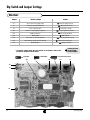
• Note which sensor is reading consistently higher
(A vs B or t vs H).
4. Unplug the two sensors from the circuit board and
interchange them (ie, plug the one that was in the
A or t jack into the B or H jack and vice versa).
5. Press a panel button if any "stray" faults appeared
during the process. (Stray fault are normal when
sensors are unplugged then plugged back in while
the system is running.)
6. Within a minute or so*, see if the same or other
sensor is now reading consistently higher:
• If the same sensor (A vs B or t vs H) is
reading higher after the sensor interchange,
the problem is on the circuit board. Replace
the circuit board.
• If the opposite sensor is now reading higher, the
problem is with the sensor(s). Replace
the sensor set.
* If you wait more than 2 minutes after
plugging the sensors back in, heating may
start (even outside a filter in Economy or
Sleep mode) due to a stray Cd/CLd/COLD
WATER condition usually detected when
sensors are being plugged in while the
system is running.
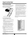
7. If there is a message indicating an open or faulty
sensor:
• Unplug the sensor set (but leave the original
sensors in the heater) and plug in the test
sensor set. Put both sensors into the same
www.balboa-instruments.com
cup of warm water (ideally above the set
temperature, so the spa won't try to heat
during this test, as there is no heater
protection during this test) and verify that
they read the same temperature
(within 1°F/0.5°C).
• If the problem is solved, replace the sensor
set. If the problem is not solved, do not
replace the sensor set.
• Plug in the original sensor set to verify that there is
not a connection problem.
• If the problem continues after following the above
steps, then replace the circuit board.
8. If you cannot get readings of the sensors on the
topside panel even in M7 Test Mode / Analysis Display
Mode (for example, because the system always
indicates an Overheat condition when it shouldn’t):
• You can use an ohmmeter to evaluate the validity
of each sensor independently (after unplugging the
sensors from the circuit board).
• You will need sharp tips on the meter probes(or a
Balboa Logic Jumper on a Stick) to be able to
make contact with the little bit of metal of each of
the two sensor wires visible through a window on
the connector.
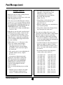
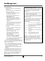
• The following chart shows what temperatures
certain resistance values translate to:
1.5k
3.0k
5.0k
7.0k
9.0k
10.0k
11.1k
11.7k
12.1k
12.7k
13.2k
13.6k
14.1k
231F 110.5C
190F 88.0C
162F 72.0C
144F 62.5C
131F 55.0C
126F 52.5C
121F 49.5C
119F 48.5C
117F 47.5C
115F 46.0C
113F 45.0C
112F 44.5C
110F 43.5C
14.7k 108F 42.5C
15.4k 106F 41.0C
16.2k 104F 40.0C
17.2k 101F 38.5C
18.1k 99F 37.0C
20.2k 94F 34.5C
25.5k 84F 29.0C
30.0k 77F 25.0C
40.0k 65F 18.5C
55.0k 53F 11.5C
95.0k 32F 0.0C
184.0k 9F -13.0C
320.0k -9F -23.0C
21