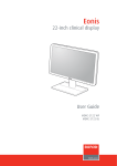
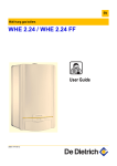
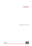
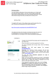
1
AP20 & AP24 Fan Replacement Kit
Installation Manual
R59770891/00
28/09/2015
Barco NV
President Kennedypark 35, 8500 Kortrijk, Belgium
Phone: +32 56.36.82.11
Fax: +32 56.36.883.86
Support: www.barco.com/en/support
Visit us at the web: www.barco.com
Printed in Belgium
Changes
Barco provides this manual ’as is’ without warranty of any kind, either expressed or implied, including but not limited to the implied warranties or merchantability and fitness for a particular purpose. Barco may make improvements and/or changes to the product(s) and/or the
program(s) described in this publication at any time without notice.
This publication could contain technical inaccuracies or typographical errors. Changes are periodically made to the information in this
publication; these changes are incorporated in new editions of this publication.
The latest edition of Barco manuals can be downloaded from the Barco web site www.barco.com or from the secured Barco web site
https://www.barco.com/en/signin.
Copyright ©
All rights reserved. No part of this document may be copied, reproduced or translated. It shall not otherwise be recorded, transmitted or
stored in a retrieval system without the prior written consent of Barco.
Trademarks
Brand and product names mentioned in this manual may be trademarks, registered trademarks or copyrights of their respective holders.
All brand and product names mentioned in this manual serve as comments or examples and are not to be understood as advertising for
the products or their manufacturers.
1. Fan replacement kit
1. FAN REPLACEMENT KIT
Overview
•
Kit content
•
Installation process overview
•
Remove the top cover
•
Remove the front panel assembly
•
Remove the power supply assembly
•
Replace the fan assembly
•
install the power supply assembly
•
Install the front panel assembly
•
Install the top cover
WARNING:
1.1
This manual is only intended for qualified service personnel.
Kit content
What’s in the box?
This kit contains the following:
•
1 fan subassembly
•
4 Keps nuts, 6–32, steel, clear zinc finish
•
4 screws, 6–32 x 1/2” flat-head Phillips, 100 degree, steel, clear zinc
Purpose of the spare part kit
The fan subassembly in the fan replacement kit is designed to replace the fan of the AP20 and AP24 audio processor. This document
describes in detail the replacement procedures.
1.2
Installation process overview
About this chapter
This chapter gives an overview of the different stages in the installation process. The stages displayed in bold are described in more
detail in this manual. More information about the other stages can be found in the service manual of the audio processor.
Safety warnings
WARNING:
Servicing must be done by authorized and qualified technical personnel only, which are thoroughly familiar with the product and all of the proper safety checks of this product.
CAUTION: The AP20 and AP24 audio processors contain parts that are static sensitive. Use caution when
handling to avoid damage and avoid touching circuit boards.
When removing or installing internal cables, keeping one hand on the chassis will help to ground you with
respect to internal circuitry.
It is a good idea to stand on a linoleum or cement floor (not carpet) when handling the processor.
Installation from A to Z
1. Find a suitable workspace to perform the procedure. Antistatic foam or an antistatic mat is an ideal work surface.
2. Turn off the processor’s rear panel power switch and unplug the power cord.
3. Remove the top cover. See "Remove the top cover", page 2
R59770891 AP20 & AP24 FAN REPLACEMENT KIT 28/09/2015
1
1. Fan replacement kit
4. Remove the front panel assembly. See "Remove the front panel assembly", page 2
5. Remove the power supply assembly. See "Remove the power supply assembly", page 4
6. Replace the fan assembly. See "Replace the fan assembly", page 4
7. Install the power supply assembly. See "install the power supply assembly", page 6
8. Install the front panel assembly. See "Install the front panel assembly", page 6
9. Install the top cover. See "Install the top cover", page 7
10.Connect the audio processor to the AC power and turn it on.
11. Verify if the new fan is working correctly.
1.3
Remove the top cover
Necessary tools
#2 Phillips screwdriver
How to remove the top cover from the audio processor?
1. Remove the two 4–40 x 1/4” pan head Phillips screws from both sides of the top cover.
Image 1-1
2. Slide the top cover to the back of the processor.
Image 1-2
3. Lift the top cover up to remove it.
1.4
Remove the front panel assembly
Necessary tools
#1 Phillips screwdriver
How to remove the front panel assembly?
1. Carefully turn the processor on its side.
2. Remove four 4–40 x 3/16” flat-head Phillips screws from the bottom.
2
R59770891 AP20 & AP24 FAN REPLACEMENT KIT 28/09/2015
1. Fan replacement kit
Image 1-3
3. Place the processor back down with the top facing upwards.
4. Gently remove the ribbon cable connector from the front panel.
Image 1-4
Tip:
Pull evenly on both sides and be careful not to bend pins or damage the ribbon cable connector.
Do not tug on the wires to remove the connector, as this ma damage the cable.
5. Remove four 4–40 x 3/16” flat-head Phillips screws on both sides of the processor (eight in total).
Image 1-5
Note:
Be careful when removing the last screws.
6. Fold the front panel down and away, to provide more room to access to the fan.
Note: be careful not to stress any of the cables that are still attached.
R59770891 AP20 & AP24 FAN REPLACEMENT KIT 28/09/2015
3
1. Fan replacement kit
1.5
Remove the power supply assembly
Necessary tools
#1 Phillips screwdriver
How to remove the power supply assembly?
1. Remove three of the four 6–32 x 1/4” pan-head Phillips screws that hold the power supply in place; These screws can be found
on the side.
Image 1-6
2. Remove the fourth screw, while holding the power supply. Do this so that the power supply will not fall.
3. Carefully lift the power supply out and set it on top of the card cage.
Tip:
No cables need to be removed from the power supply, but make sure not to stress the cables.
Image 1-7
1.6
Replace the fan assembly
Necessary tools
•
A small flat-blade screwdriver
•
#2 Phillips screwdriver
•
5/16” combination wrench
Necessary parts
•
Sub-Assembly, Fan
•
Keps nuts, 6–32, steel, clear zinc finish (4 pieces)
•
Screw, 6–32 x 1/2” flat head Phillips, 100°, steel, clear zinc (4 pieces)
How to replace the fan assembly?
1. Remove the fan power connector from the front panel.
Tip:
Use a small flat-blade screwdriver to help lift up the connector out of the socket.
Caution:
4
Do not pull the power connector directly up on the wires. This will pull them out of the connector.
R59770891 AP20 & AP24 FAN REPLACEMENT KIT 28/09/2015
1. Fan replacement kit
Image 1-8
2. Remove four 6–32 x 1/2” flat-head Phillips screws and four 6–32 Keps nuts holding the fan to the chassis.
Image 1-9
3. Remove the fan assembly.
4. Install the new fan assembly, using four 6–32 x 1/2” flat-head Phillips screws and four 6–32 Keps nuts.
Note: New screws and nuts for this are included in the kit, as existing hardware may be covered in old Loctite.
Make sure that the wires and arrows indicating air flow direction are in the correct orientation.
Image 1-10
5. Connect the fan power cable to the front panel board socket CN1. The connector is keyed to go into the socket in only one
direction.
R59770891 AP20 & AP24 FAN REPLACEMENT KIT 28/09/2015
5
1. Fan replacement kit
Image 1-11
1.7
install the power supply assembly
Necessary tools
#1 Phillips screwdriver
Necessary parts
Four 6–32 x 1/4” pan-head Phillips screws
How to install the power supply assembly?
1. Move the power supply back into place, taking care of the cabling.
2. Install the power supply, using four 6–32 x 1/4” pan-head Phillips screws.
Image 1-12
1.8
Install the front panel assembly
Necessary tools
#1 Phillips screwdriver
Necessary parts
eight 4–40 x 3/16” flat-head Phillips screws
How to install the front panel assembly?
1. Slide the front panel back into the chassis.
2. Insert four 4–40 x 3/16” flat-head Phillips screws on each side to secure.
6
R59770891 AP20 & AP24 FAN REPLACEMENT KIT 28/09/2015
1. Fan replacement kit
Image 1-13
3. Insert the ribbon cable back into the socket.
Image 1-14
Note:
be careful not to bend pins.
4. Carefully turn the processor on its side.
5. Install four 4–40 x 3/16” flat-head Phillips screws in bottom plate.
Image 1-15
6. Place the processor back down.
7. Inspect the processor to make sure that all connectors are properly seated and the screws and nuts are tight.
1.9
Install the top cover
Necessary tools
#1 Phillips screwdriver
R59770891 AP20 & AP24 FAN REPLACEMENT KIT 28/09/2015
7
1. Fan replacement kit
Necessary parts
Two 4–40 x 1/4” pan-head Phillips screws
How to install the top cover?
1. Place the top cover correctly on the top of the processor.
Note: There is a lip that slides under the front panel assembly in front and a back lip that slides over the top lip of the rear panel
assembly.
Image 1-16
Image 1-17
2. Once the top cover is properly seated, install two 4–40 x 1/4” pan-head Phillips screws.
Note: If the screw holes are not lined up correctly, the cover is not seated correctly. Adjust the top cover if necessary.
Image 1-18
8
R59770891 AP20 & AP24 FAN REPLACEMENT KIT 28/09/2015